EP1902866A1 - Luftloser Reifen - Google Patents
Luftloser Reifen Download PDFInfo
- Publication number
- EP1902866A1 EP1902866A1 EP07253693A EP07253693A EP1902866A1 EP 1902866 A1 EP1902866 A1 EP 1902866A1 EP 07253693 A EP07253693 A EP 07253693A EP 07253693 A EP07253693 A EP 07253693A EP 1902866 A1 EP1902866 A1 EP 1902866A1
- Authority
- EP
- European Patent Office
- Prior art keywords
- link
- links
- circumferential
- rim
- link members
- Prior art date
- Legal status (The legal status is an assumption and is not a legal conclusion. Google has not performed a legal analysis and makes no representation as to the accuracy of the status listed.)
- Granted
Links
- 238000006073 displacement reaction Methods 0.000 claims abstract description 64
- 230000007246 mechanism Effects 0.000 claims abstract description 31
- 230000008878 coupling Effects 0.000 claims abstract description 8
- 238000010168 coupling process Methods 0.000 claims abstract description 8
- 238000005859 coupling reaction Methods 0.000 claims abstract description 8
- 238000006243 chemical reaction Methods 0.000 description 17
- 230000009471 action Effects 0.000 description 9
- 238000005096 rolling process Methods 0.000 description 6
- 230000008859 change Effects 0.000 description 4
- 239000007787 solid Substances 0.000 description 3
- 230000007935 neutral effect Effects 0.000 description 2
- DOSMHBDKKKMIEF-UHFFFAOYSA-N 2-[3-(diethylamino)-6-diethylazaniumylidenexanthen-9-yl]-5-[3-[3-[4-(1-methylindol-3-yl)-2,5-dioxopyrrol-3-yl]indol-1-yl]propylsulfamoyl]benzenesulfonate Chemical compound C1=CC(=[N+](CC)CC)C=C2OC3=CC(N(CC)CC)=CC=C3C(C=3C(=CC(=CC=3)S(=O)(=O)NCCCN3C4=CC=CC=C4C(C=4C(NC(=O)C=4C=4C5=CC=CC=C5N(C)C=4)=O)=C3)S([O-])(=O)=O)=C21 DOSMHBDKKKMIEF-UHFFFAOYSA-N 0.000 description 1
- 229910000838 Al alloy Inorganic materials 0.000 description 1
- 229910052782 aluminium Inorganic materials 0.000 description 1
- XAGFODPZIPBFFR-UHFFFAOYSA-N aluminium Chemical compound [Al] XAGFODPZIPBFFR-UHFFFAOYSA-N 0.000 description 1
- 238000007796 conventional method Methods 0.000 description 1
- 230000003247 decreasing effect Effects 0.000 description 1
- 238000010586 diagram Methods 0.000 description 1
- 230000000694 effects Effects 0.000 description 1
- 239000000835 fiber Substances 0.000 description 1
- 239000007789 gas Substances 0.000 description 1
- 238000005304 joining Methods 0.000 description 1
- 238000004519 manufacturing process Methods 0.000 description 1
- 239000007769 metal material Substances 0.000 description 1
- 238000000034 method Methods 0.000 description 1
- 230000001953 sensory effect Effects 0.000 description 1
Images




Classifications
-
- B—PERFORMING OPERATIONS; TRANSPORTING
- B60—VEHICLES IN GENERAL
- B60C—VEHICLE TYRES; TYRE INFLATION; TYRE CHANGING; CONNECTING VALVES TO INFLATABLE ELASTIC BODIES IN GENERAL; DEVICES OR ARRANGEMENTS RELATED TO TYRES
- B60C7/00—Non-inflatable or solid tyres
- B60C7/10—Non-inflatable or solid tyres characterised by means for increasing resiliency
- B60C7/14—Non-inflatable or solid tyres characterised by means for increasing resiliency using springs
-
- Y—GENERAL TAGGING OF NEW TECHNOLOGICAL DEVELOPMENTS; GENERAL TAGGING OF CROSS-SECTIONAL TECHNOLOGIES SPANNING OVER SEVERAL SECTIONS OF THE IPC; TECHNICAL SUBJECTS COVERED BY FORMER USPC CROSS-REFERENCE ART COLLECTIONS [XRACs] AND DIGESTS
- Y10—TECHNICAL SUBJECTS COVERED BY FORMER USPC
- Y10T—TECHNICAL SUBJECTS COVERED BY FORMER US CLASSIFICATION
- Y10T152/00—Resilient tires and wheels
- Y10T152/10—Tires, resilient
Definitions
- the present invention relates to a non-pneumatic tire. More particularly, the present invention proposes a technique capable of eliminating a necessity of filling a pressurized air and easily providing vertical, longitudinal and lateral stiffnesses of required magnitudes to a tire.
- a pneumatic tire is a widely and commonly used for motor vehicles and the like, but it has an unavoidable drawback that filled-air pressure is decreased and even lost due to a puncture or the like.
- non-pneumatic tires which can eliminate a necessity of filling a pressurized air have been proposed.
- a non-pneumatic tire is a solid tire having a solid structure, but it involves another drawbacks of increasing both of the weight and hardness, so that, as compared with a pneumatic tire, sufficient riding comfort and driveability cannot be secured and rolling resistance is increased.
- the solid tire has not been commonly used except for a special application.
- stiffness refers to a magnitude of elasticity against a shear deformation.
- the present invention addresses to solve these drawbacks which conventional techniques encompasses, and its object is to provide a pneumatic tire which can eliminate a necessity of filling a pressurized air or other gases to obviate a possibility of decrease or loss of the internal pressure of the tire and can easily provide desired vertical, longitudinal and lateral stiffnesses in a mutually independent state.
- One aspect of a non-pneumatic tire according to the present invention comprises a rim member, a ring member disposed at an outer circumferential side of the rim member and provided with a tread on a circumferential face, and a plurality of link mechanisms circumferentially spaced at a given distance and coupling the rim member with the ring member, wherein each of the link mechanisms consists of a pair of link members aligned, for example, in a meridian direction, each of the link members consists of a link which is connected at a first with a side portion of the rim member and which is swingable in the circumferential and meridian directions, for example, by a universal joint, and another link which is connected at a first end with a side portion of the ring member and which is swingable in the circumferential and meridian directions, for example, by a universal joint, with respective second ends of the links being hingedly connected one another to make the links swingable in the meridian direction, and one or more kinds
- one of the elastic means preferably consists of a spring member such as a rubber elastic body, a coil spring or an air spring which connects respective hinge connections of the second ends of the links of the pair of link members with each other and which has a natural length under an unloaded condition.
- another one of the elastic means consists of a torsion spring member which is arranged at a connection of the first end of at least one of the links of the link members and which imparts a stiffness against swing displacements of the link in the circumferential direction.
- the torsion spring member may be arranged at the connections of the first ends of the both links of the link members.
- the tire is preferably provided with a further elastic means consisting of a torsion bar disposed between the respective hinge connections of the second ends of the links of the pair of link members via a pair of connecting rods having moment arms.
- Another aspect of a non-pneumatic tire according to the present invention comprises a rim member, a ring member disposed at an outer circumferential side of the rim member and provided with a tread on a circumferential face, and a plurality of link mechanisms circumferentially spaced at a given distance and coupling the rim member with the ring member, wherein each of the link mechanisms consists of a pair of link members aligned, for example, in a meridian direction, each of the link members consists of a link which is connected at a first end with a side portion of the rim member and which is swingable in the circumferential and meridian directions and another link which is connected at a first end with a side portion of the ring member and which is swingable in the circumferential and meridian directions, with respective second ends of the links being hingedly connected one another to make the links swingable in the meridian direction, and a torsion spring member imparting a stiffness against swing displacements of the links in the
- the tire preferably has another torsion spring member which is arranged at a connection of the first of at least one of the links of the link members and imparts a stiffness against swing displacements of the link in the circumferential direction.
- a torsion bar is preferably disposed between the respective hinge connections of the second ends of the links of the pair of link members via a pair of connecting rods having moment arms.
- a non-pneumatic tire comprises a rim member, a ring member disposed at outer circumferential side of the rim member and provided with a tread on a circumferential face, and a plurality of link mechanisms circumferentially spaced at a given distance and coupling the rim member with the ring member, wherein each of the link mechanisms consists of a pair of link members, each of the link members consists of a link which is connected at a first end with a side portion of the rim member and which is swingable in the circumferential and meridian directions and another link which is connected at a first end with a side portion of the ring member and which is swingable in the circumferential and meridian directions, with respective second ends of the links being hingedly connected one another to make the links swingable in the meridian direction, an elastic means imparting a stiffness against relative displacements in the radian, circumferential and width directions with respect to the rim and ring members is provided on the link
- the elastic means preferably consists of a torsion spring member which is arranged at a connection of the first end of at least one of the links of the link members and which imparts a stiffness against swing displacements of the link in the circumferential and meridian directions.
- the elastic means consisting of the torsion spring may thus be arranged at connections of the first ends of the both links of the link members.
- the elastic means may consist of a torsion spring member which is arranged at a connection of the first end of either one of the link of the link members and which imparts a stiffness against swing displacements of the link in the circumferential direction, and another torsion spring member which is arranged at a connection of the first end of the other link of the link members and which imparts a stiffness against swing displacements of the link in the meridian direction.
- one ore more kinds of elastic means imparting a required stiffness against relative displacements in the radian, circumferential and width directions with respect to the rim and ring members is provided on the link mechanisms consisting of the pair of link members which are aligned, for example, in the meridian direction and which connect the rim member with the ring member on which the tread is formed.
- This can eliminate a necessity of filling an air pressure or any other internal pressure into the tire provided with a tread on the circumferential face of the ring member, and can easily provide vertical, longitudinal and lateral stiffnesses of required magnitudes to the tire on the basis of a pre-selected elastic force and according to the amount of the displacement from the neutral position, with the stiffnesses being independent with each other.
- one of the elastic means consists of a spring member which connects respective hinge connections of the second ends of the links of the pair of link members with each other and which has a natural length under a unloaded condition, the various required stiffnesses can be effectively exerted by the spring member.
- a compressive or tensile reactive force is produced on the spring member by a displacement of the link member in the compressive direction in the grounding surface side of the tire tread due to a displacement of the ring member approaching to the rim member, so that a required vertical stiffness can be exerted on the tire.
- a tensile or compressive reactive force is produced on the spring member by a relative displacement of the link member in the elongation direction in the grounding surface side due to a relative displacement of the ring member in a leading or lagging phase with respect to the rim member, so that a required longitudinal stiffness can be exerted on the tire.
- a tensile or compressive reactive force is produced on the spring member by an increase of the distance between the pair of link members and the hinge connection due to a relative displacement of the ring member in the width direction of the rim member, so that a required lateral stiffness can be exerted on the tire.
- the longitudinal stiffness of the tire can be selectively enhanced under an action of the torsion spring member.
- the lateral stiffness of the tire can be selectively increased by a torsional force applied to the torsion bar via the moment arm due to a mutual change of the radial position of the above-mentioned hinge connection or, in other words, the radial height of the hinge connection from the rim member on the occasion of a relative displacement of the ring member in the width direction caused by the action of a lateral load to the tire.
- a torsion spring member imparting a stiffness against swing displacements of the links in the meridian direction is disposed between the respective hinge connections of the second ends of the links of the pair of link members constituting the link mechanism, so that the torsion spring member on the hinge connections can effectively exert the stiffnesses of the magnitudes according to the amounts of the swing displacements of the links from the neutral position against relative displacements in the radial, circumferential and width directions of the tire.
- the torsion spring members disposed between the hinge connecting potions of the link members can impart required stiffnesses on the basis of, in case of a relative displacement of the ring member and the rim member in the radial direction, the swing displacements of the links in the direction to which the link member is compressively deformed, and, in case of a relative displacement of the ring member and rim member in the circumferential direction, the swing displacements of the links in the direction to which the link member is expansively deformed.
- the torsion spring members can impart required lateral stiffness on the basis of the change of the crossing angle of the links due to the link member being deformed in the width direction without deformations in either of the compressive or extensive direction.
- the longitudinal stiffness of the tire alone can be selectively enhanced, as mentioned above.
- the torsion bar is disposed between the respective hinge connections of the second ends of the links of the pair of link members via the pair of connecting rods having movement arms, the lateral stiffness of the tire alone can be selectively enhanced, as mentioned above.
- an elastic means imparting a stiffness against relative displacements of the rim and ring members in the radial and circumferential directions is provided on the link mechanism and a torsion bar is additionally disposed between the respective hinge connections of the second ends of the links of the pair of link members via the pair of connecting rods having the moment arms, so that the required vertical and longitudinal stiffnesses can be imparted to the tire under the action of the elastic means as well as the required lateral stiffness can be provided to the tire under the action of the torsion bar.
- the elastic means consists of a torsion spring member which is arranged at the connection of the first end of at least one of the links of the link members and which imparts a stiffness against the swing displacement in the meridian and circumferential directions
- the vertical and longitudinal stiffnesses can be adjusted as required with the small number of the arranged elastic means. This is especially effective for a case where torsion spring members constituting the elastic means are arranged at the connections of the first ends of both links.
- the elastic means consists of a torsion spring member which is arranged at the connection of the first end of either one of the link of each link members and which imparts a stiffness against the swing displacement of the link in the meridian direction, and another torsion spring member which is arranged at the connection of the first end of the other link and which imparts a stiffness against the swing displacement of the link in the circumferential direction to, thereby, separate the function of the torsion springs, each of the vertical and longitudinal stiffnesses of the tire can be easily adjusted as desired in a mutually independent state.
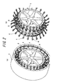
- the illustrated tire has a rim member 1 equipped with a connection to an axle, a ring member 3 disposed at outer circumferential side of the rim member 1 and provided with a tread 2 on a circumferential face (in this embodiment, an integrated ring which may be made of a metal material such as aluminum and aluminum alloy), and a plurality of link mechanisms 4 circumferentially spaced at a given distance and coupling the rim member 1 and the ring member 3.
- each of the link mechanisms 4 consists of a pair of link members 7a, 7b aligned in a meridian direction
- the link members 7a, 7b consist of links 5a, 5b, respectively, which are connected at a first end with side portions of the rim 1 member and which are swingable in the circumferential and meridian directions of the tire
- another links 6a, 6b, respectively which are connected at a first end with side portions of the ring member 3 and which are also swingable in the circumferential and meridian directions with respective second ends of the links being hingedly connected one another to make the links 5a and 6a, 5b and 6b swingable in the meridian direction.
- the above-mentioned link mechanisms 4 are provided with one or more kinds of elastic means imparting a stiffness against relative displacements in the radian, circumferential and width directions with respect to the rim member 1 and the ring member 3.
- the elastic means shown in Fig. 3 consists of a spring member 9 such as a rubber elastic body, a coil spring, an air spring or a rubber elastic body reinforced with fiber connecting hinge connections 8a, 8b of the second ends of the links 5a and 6a, 5b and 6b of the pair of link members 7a, 7b, respectively, with each other.
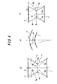
- the spring member 9 has a natural length at which neither a compressive reaction force and a tensile reaction force is produced under an unloaded condition of the tire. For example, when the rim member 1 and the ring member 3 approach with each other in the radial direction immediately under the load as shown by an imaginary line in Fig. 4(a), a required vertical stiffness is produced by a compressive reaction force due to a compressive deformation of the spring member 9. When the rim member 1 and the ring member 3 are relatively displaced in the circumferential direction as shown in Fig.
- a required longitudinal stiffness is produced by a tensile reaction force due to a tensile deformation of the spring member 9 cause by an elongation of the entire length of the link mechanisms 4 or, directly, the link members 7a, 7b.
- the spring member 9 is subjected to a tensile deformation under swing displacements of the links 5a and 6a, 5b and 6b at the hinge connections 8a, 8b, respectively. As a result, the spring member 9 imparts a required lateral stiffness due to the tensile reaction force.
- the link mechanisms 4 may be so configured that the hinge connections 8a, 8b of the link members 7a, 7b, respectively, are laid to protrude outwardly in the width direction, which is opposite of the configuration shown in Fig. 3.
- the spring member 9 joining the hinge connections 8a, 8b produces a tensile reaction force against an approaching displacement of the rim member 1 and the ring member 3, produces a compressive reaction force against a relative displacement of the rim member 1 and the ring member 3 in the circumferential direction and produces a compressive reaction force against a relative displacement of the rim member 1 and the ring member 3 in the width direction.
- the spring member 9 functions to yield a required stiffness.
- a torsion member such as a torsion spring member, a rubber bushing and a torsion bar which is arranged at the connection of the first end of at least one of the links 5a and 6a, 5b and 6b of the link members 7a, 7b and which impart a stiffness against swing displacements of the link in the circumferential direction
- the longitudinal stiffness of the tire can be arbitrarily increased by a torsional reaction force of the torsion spring member on the occasion of a relative displacement of the rim member 1 and the ring member 3 in the circumferential direction as shown in Fig. 4(b). This is also applied to an opposite relative displacement in the circumferential direction.
- a further elastic means consists of a torsion bar 12 disposed between the respective hinge connections 8a, 8b of the second ends of the links 5a and 6a, 5b and 6b of the pair of link members 7a, 7b via a pair of connecting rods 11 a, 11 b, as shown in Fig. 6 of a perspective view of its primal part
- the torsion bar 12 is torsionally deformed, as shown in Fig. 7(b), by the moment arms 10a, 10b of the pair of connecting rods 11a, 11b, respectively, due to the change of the radial height, as shown by an imaginary line in Fig.
- the hinge connections 8a, 8b on the occasion of the relative displacement of the rim member 1 and the ring member 3 in the width direction.
- the lateral stiffness of the tire can be increased as required by a torsional reaction force of the torsion bar 12.
- the torsion bar 12 can function in the same manner against the relative widthwise displacement opposed to the illustrated direction.
- torsion spring members (not shown) imparting a stiffness against swing displacements of the links 5a and 6b, 5b and 6b in the meridian direction are provided between the hinge connections 8a, 8b of the second ends of the link 5a and 6a, 5b and 6b of the pair of link members 7a, 7b, respectively.
- the torsion spring members in this embodiment can provide required vertical, longitudinal and lateral stiffnesses to the tire on the basis of swing displacements of the links 5a and 6a, 5b and 6b in the same manner as mentioned above for the spring member 9.
- the radial lengths of the link members 7a, 7b get shorter so that the above-mentioned torsion spring member produces a torsional reaction force
- the entire lengths of the link members 7a, 7b get longer so that the torsion spring member produces a torsional reaction force
- the crossing angles of the links change at the hinge connections 8a, 8b of the link members 7a, 7b, respectively, as shown in Figs. 4(c) and 7(a) so that the torsional spring members produce torsional forces. Production of these reaction forces imparts the vertical, longitudinal and lateral stiffness of the tire.
- a torsion bar 12 may be disposed between the respective hinge connections 8a, 8b of the links 5a and 6a, 5b and 6b of the pair of link members 7a, 7b via a pair of connecting rods 11a, 11b having moment arms 10a, 10b.
- the lateral stiffness of the tire can be appropriately enhanced by the torsional reaction force produced by the torsion bar 12, as mentioned above with reference to Fig. 7.
- an appropriate elastic means imparting a stiffness against relative displacement of the rim member 1 and ring member 3 in the radial and circumferential directions is provided on the link mechanisms 4.
- a torsion bar is disposed between the respective hinge connections 8a, 8b of the second ends of the links 5a and 6a, 5b and 6b of the pair of link members 7a, 7b via a pair of connecting rods 11a, 11b having moment arms 10a, 10b, as mentioned above with reference to Fig. 6.
- the above-mentioned elastic means may consist of a torsion spring member which is arranged at the connection of the first end of at least one of the links 5a and 6a, 5b and 6b of the link members 7a, 7b and which imparts a stiffness against swing displacements of the links in both of the meridian and circumferential directions, or a combination of a torsion spring member which is arranged at the connection of the first end of at least one of the links 5a and 6a, 5b and 6b of the link members 7a, 7b and which imparts a stiffness against swing displacements of the links in both of the meridian and circumferential directions and another torsion member which is arranged at the connection of the first end of the other links and which imparts a stiffness against a swing displacement of the link in the circumferential direction.
- the vertical and longitudinal stiffnesses of the tire can be imparted through the deformation reaction force of the elastic means consisting of the torsion spring member or the like, and the lateral stiffness can be imparted through the torsion reaction force of the torsion bar 12.
- Fig. 8 is a perspective view of a modified embodiment of the ring member.
- the link mechanisms 4 are coupled at the first ends with the side of the rim member 1, and at the second ends with ends of a plurality of segments 13 in their extending directions which are aligned in the circumferential direction with small spaces therebetween.
- An elastic ring 14 such as a belt is bonded on the circumferential face of the segments 13. In this way, the segments 13 and the elastic ring 14 constitute the ring member 3.
- a non-pneumatic tire having a tread formed on the circumferential face of the ring member 3 can have lower stiffness of the ring member 3 than that of the tire shown in Figs. 1 and 2, so that larger grounding area of the tire during a rotation under load can be ensured.
- the desired vertical, longitudinal and lateral stiffnesses of the tire can be mutually independently and easily obtained by imparting a required stiffness against relative displacements of the rim member 1 and the ring member 3 in the radial, circumferential and width directions with any of the above-mentioned means.
- a conventional pneumatic tire of the size 225/55ZR17 (internal air pressure: 230kPa) is prepared as a control and Example tires 1 and 2 of the same size of the control tire are also prepared. For these tires, weight, riding comfort, driveability and rolling resistance are measures. The results are shown in Table 1.
- Example tire 1 has a basic structure as shown in Figs. 1 and 2, and has a torsion bar 12 in addition to a coil spring as a spring member 9.
- Example tire 2 has a basic structure as shown in Fig. 8, and additionally has the same spring member 9 and a torsion bar 12. Further, both of Example tires 1 and 2 is provided with a torsion bar at the connections of the links 5a, 5b to the rim member 1.
- the riding comfort is evaluated from a feeling obtained by an actual vehicle traveling test in which the tire wheel is mounted on a passenger vehicle of 3000 cc displacement and tested under a load condition corresponding to two passengers.
- the driveability is evaluated by a driver from a sensory feeling under the above-mentioned test condition.
- the tire wheel is rotated on a test drum machine at 80 km/h under an action of a load of 4.0 kN and a resistance transmitted to a drum shaft is measured to give the rolling resistance.
- Table 1 the results are indicated in index values and the larger index value except for the weight means a better result.
- the heavier tire has the larger index value.
- Example tire 1 has a superior rolling resistance but a slightly inferior riding comfort due to its higher ring stiffness and a smaller deformation of the tread grounding portion, and has a slightly inferior driveability due to its smaller grounding area. It is also appreciated that Example tire 2 can simultaneously improve the riding comfort and driveability since it can enhance the lateral and longitudinal stiffnesses while suppressing the vertical stiffness to, thereby, ensure a sufficient grounding area.
Landscapes
- Engineering & Computer Science (AREA)
- Mechanical Engineering (AREA)
- Tires In General (AREA)
Applications Claiming Priority (1)
| Application Number | Priority Date | Filing Date | Title |
|---|---|---|---|
| JP2006259121A JP5087252B2 (ja) | 2006-09-25 | 2006-09-25 | 非空気入りタイヤ |
Publications (2)
| Publication Number | Publication Date |
|---|---|
| EP1902866A1 true EP1902866A1 (de) | 2008-03-26 |
| EP1902866B1 EP1902866B1 (de) | 2009-12-02 |
Family
ID=38825541
Family Applications (1)
| Application Number | Title | Priority Date | Filing Date |
|---|---|---|---|
| EP07253693A Not-in-force EP1902866B1 (de) | 2006-09-25 | 2007-09-18 | Luftloser Reifen |
Country Status (4)
| Country | Link |
|---|---|
| US (1) | US7743806B2 (de) |
| EP (1) | EP1902866B1 (de) |
| JP (1) | JP5087252B2 (de) |
| DE (1) | DE602007003536D1 (de) |
Cited By (12)
| Publication number | Priority date | Publication date | Assignee | Title |
|---|---|---|---|---|
| WO2009064075A1 (en) * | 2007-11-14 | 2009-05-22 | Young-Ill Chon | Non-pneumatic wheel and wheel, suspension and tire used therein |
| US8104524B2 (en) | 2007-03-27 | 2012-01-31 | Resilient Technologies Llc | Tension-based non-pneumatic tire |
| US8109308B2 (en) | 2007-03-27 | 2012-02-07 | Resilient Technologies LLC. | Tension-based non-pneumatic tire |
| US8176957B2 (en) | 2009-07-20 | 2012-05-15 | Resilient Technologies, Llc. | Tension-based non-pneumatic tire |
| US8714217B2 (en) | 2007-11-14 | 2014-05-06 | Young-Ill Chon | Non-pneumatic wheel assembly and wheel, suspension and tire used therein |
| US8944125B2 (en) | 2009-07-20 | 2015-02-03 | Polaris Industries Inc. | Tension-based non-pneumatic tire |
| US9108470B2 (en) | 2008-09-29 | 2015-08-18 | Polaris Industries Inc. | Run-flat device |
| US9573422B2 (en) | 2012-03-15 | 2017-02-21 | Polaris Industries Inc. | Non-pneumatic tire |
| US9662939B2 (en) | 2009-07-28 | 2017-05-30 | Bridgestone Americas Tire Operations, Llc | Tension-based non-pneumatic tire |
| EP3321076A1 (de) * | 2016-11-15 | 2018-05-16 | The Goodyear Tire & Rubber Company | Verfahren zur herstellung einer rad- und reifenanordnung |
| CN111301062A (zh) * | 2020-03-19 | 2020-06-19 | 燕山大学 | 基于负泊松比结构的非充气轮胎以及轮胎的工作方法 |
| WO2021148529A1 (en) * | 2020-01-24 | 2021-07-29 | Tree Associates Ltd. | Tyre |
Families Citing this family (37)
| Publication number | Priority date | Publication date | Assignee | Title |
|---|---|---|---|---|
| JP5401155B2 (ja) * | 2008-07-09 | 2014-01-29 | 株式会社ブリヂストン | 非空気入りタイヤ |
| US20110180194A1 (en) * | 2008-09-29 | 2011-07-28 | Resilient Technologies, Llc | Run-flat device |
| JP2010083401A (ja) | 2008-10-01 | 2010-04-15 | Bridgestone Corp | 非空気入りタイヤ |
| JP5401157B2 (ja) * | 2008-10-27 | 2014-01-29 | 株式会社ブリヂストン | 非空気入りタイヤ |
| JP5571315B2 (ja) * | 2009-03-11 | 2014-08-13 | 株式会社ブリヂストン | 非空気入りタイヤ |
| US8141606B2 (en) | 2009-05-29 | 2012-03-27 | The Goodyear Tire & Rubber Company | Tire |
| JP5401192B2 (ja) * | 2009-07-22 | 2014-01-29 | 株式会社ブリヂストン | 非空気入りタイヤの製造装置および非空気入りタイヤの製造方法 |
| US8662122B2 (en) | 2010-05-14 | 2014-03-04 | The Goodyear Tire & Rubber Company | System for non-pneumatic support of a vehicle |
| US9616713B2 (en) | 2010-08-30 | 2017-04-11 | The Goodyear Tire & Rubber Company | Non-pneumatic tire |
| JP5735903B2 (ja) * | 2010-11-29 | 2015-06-17 | 住友ゴム工業株式会社 | 車輪体を用いたタイヤの転がり抵抗測定方法 |
| CN103402786B (zh) * | 2011-03-09 | 2017-05-24 | 横滨橡胶株式会社 | 轮胎车轮组装体 |
| US8720504B2 (en) | 2011-06-17 | 2014-05-13 | The Goodyear Tire & Rubber Company | System for non-pneumatic support of a vehicle |
| US9283810B2 (en) * | 2012-10-18 | 2016-03-15 | Lindsay Corporation | Wheel and tire assembly |
| CA2915483C (en) | 2013-06-15 | 2021-11-16 | Ronald Thompson | Annular ring and non-pneumatic tire |
| US9919568B2 (en) | 2013-09-24 | 2018-03-20 | Bridgestone Americas Tire Operations, Llc | Tire with toroidal element |
| KR101411103B1 (ko) * | 2013-11-06 | 2014-06-27 | 한국타이어 주식회사 | 비공기입 타이어 |
| JP6751345B2 (ja) | 2013-12-24 | 2020-09-02 | ブリヂストン アメリカズ タイヤ オペレーションズ、 エルエルシー | 不定剛性を有するエアレスタイヤ構造 |
| WO2015175804A1 (en) | 2014-05-16 | 2015-11-19 | Basf Se | Thermoplastic wheel hub |
| WO2016099476A1 (en) | 2014-12-17 | 2016-06-23 | Compagnie Generale Des Etablissements Michelin | Method and apparatus for molding non-pneumatic wheels |
| WO2016099480A1 (en) | 2014-12-17 | 2016-06-23 | Compagnie Generale Des Etablissements Michelin | A non-pneumatic tire with integrated polymeric flexible wheel center mount |
| WO2016099474A1 (en) | 2014-12-17 | 2016-06-23 | Compagnie Generale Des Etablissements Michelin | Method and apparatus for molding non-pneumatic wheels |
| US20160214435A1 (en) | 2015-01-27 | 2016-07-28 | Mtd Products Inc | Wheel assemblies with non-pneumatic tires |
| US10899169B2 (en) | 2015-01-27 | 2021-01-26 | Mtd Products Inc | Wheel assemblies with non-pneumatic tires |
| USD792332S1 (en) | 2015-06-03 | 2017-07-18 | Mtd Products Inc | Non-pneumatic tire |
| WO2016126983A1 (en) | 2015-02-04 | 2016-08-11 | Advancing Mobility, Llc. | Non-pneumatic tire and other annular devices |
| USD784917S1 (en) | 2015-06-03 | 2017-04-25 | Mtd Products Inc | Non-pneumatic tire |
| WO2017106750A1 (en) | 2015-12-16 | 2017-06-22 | Thompson Ronald H | Track system for traction of a vehicle |
| AU2017431581A1 (en) * | 2017-09-12 | 2020-03-05 | Sung Kee Lee | Airless tire |
| JP6989082B2 (ja) * | 2017-12-14 | 2022-01-05 | ブリヂストン アメリカズ タイヤ オペレーションズ、 エルエルシー | マルチピースウェブを有する非空気圧式タイヤ |
| KR102136158B1 (ko) * | 2018-12-04 | 2020-07-22 | 한국타이어앤테크놀로지 주식회사 | 형상 가변형 타이어 |
| CN109624614B (zh) * | 2019-01-21 | 2024-04-02 | 浙江利福德机械有限公司 | 一种轮胎结构 |
| CN110039957B (zh) * | 2019-04-24 | 2023-11-03 | 北京化工大学 | 一种安全绿色节能降噪非充气轮胎 |
| KR102813635B1 (ko) * | 2020-01-28 | 2025-05-29 | 삼성전자주식회사 | 적응형 가변 바퀴 |
| CN111674205B (zh) * | 2020-04-29 | 2022-06-28 | 南京航空航天大学 | 一种非充气防暴车轮电机轮边总成及其匹配方法 |
| KR20220163785A (ko) | 2021-06-03 | 2022-12-12 | 현대자동차주식회사 | 바퀴 및 이를 포함하는 이동체 |
| JP1787674S (ja) * | 2024-03-21 | 2024-12-24 | 非空気式タイヤ | |
| USD1078594S1 (en) * | 2024-07-30 | 2025-06-10 | Ironwood Designs, Llc | Wheel segment of a segmented wheel |
Citations (3)
| Publication number | Priority date | Publication date | Assignee | Title |
|---|---|---|---|---|
| GB129907A (en) | 1918-11-25 | 1919-07-24 | Augustine Dilger | A New or Improved Elastic Tyre. |
| GB139831A (en) | 1918-05-21 | 1920-03-18 | Stanly Kasprzycki | Improvements in and relating to automobile wheels |
| US1365016A (en) | 1919-08-06 | 1921-01-11 | William W Allen | Spring-tire |
Family Cites Families (13)
| Publication number | Priority date | Publication date | Assignee | Title |
|---|---|---|---|---|
| US1422818A (en) * | 1922-07-18 | Rim and tire for automobile and other wheels | ||
| US942939A (en) * | 1908-03-16 | 1909-12-14 | Edwin James Selley | Vehicle-wheel. |
| US1132127A (en) * | 1911-06-30 | 1915-03-16 | John F Sipe | Resilient wheel for vehicles. |
| US1106963A (en) * | 1913-09-20 | 1914-08-11 | Lucius R Nutting | Vehicle-wheel. |
| US1258042A (en) * | 1914-06-01 | 1918-03-05 | Fritz Pfleumer | Vehicle-wheel. |
| US1164529A (en) * | 1914-11-27 | 1915-12-14 | Otto C Koch | Spring-wheel. |
| US1173949A (en) * | 1915-06-12 | 1916-02-29 | Charles S Gilliland | Tire. |
| US1494849A (en) * | 1922-04-03 | 1924-05-20 | Lister William | Resilient wheel |
| US1484580A (en) * | 1923-03-20 | 1924-02-19 | Stitzel Frederick | Spring wheel |
| US3435872A (en) * | 1967-02-09 | 1969-04-01 | Tilden W Johnson | Safety wheel rim and buffer therefor |
| JPS4841403A (de) * | 1971-10-02 | 1973-06-18 | ||
| JPS5160003U (de) * | 1974-11-07 | 1976-05-12 | ||
| DE4301533C2 (de) * | 1993-01-21 | 1996-11-07 | Thomas Steffan | Rad mit Eigenfederung, dessen Felge mit der Nabe durch mehrere von Federn stabilisierte Gelenkhebelsysteme verbunden ist für alle mit Rädern versehenen Gegenstände insbesondere Fahrzeuge |
-
2006
- 2006-09-25 JP JP2006259121A patent/JP5087252B2/ja not_active Expired - Fee Related
-
2007
- 2007-09-18 EP EP07253693A patent/EP1902866B1/de not_active Not-in-force
- 2007-09-18 DE DE602007003536T patent/DE602007003536D1/de active Active
- 2007-09-24 US US11/860,022 patent/US7743806B2/en not_active Expired - Fee Related
Patent Citations (3)
| Publication number | Priority date | Publication date | Assignee | Title |
|---|---|---|---|---|
| GB139831A (en) | 1918-05-21 | 1920-03-18 | Stanly Kasprzycki | Improvements in and relating to automobile wheels |
| GB129907A (en) | 1918-11-25 | 1919-07-24 | Augustine Dilger | A New or Improved Elastic Tyre. |
| US1365016A (en) | 1919-08-06 | 1921-01-11 | William W Allen | Spring-tire |
Cited By (15)
| Publication number | Priority date | Publication date | Assignee | Title |
|---|---|---|---|---|
| US8104524B2 (en) | 2007-03-27 | 2012-01-31 | Resilient Technologies Llc | Tension-based non-pneumatic tire |
| US8109308B2 (en) | 2007-03-27 | 2012-02-07 | Resilient Technologies LLC. | Tension-based non-pneumatic tire |
| WO2009064075A1 (en) * | 2007-11-14 | 2009-05-22 | Young-Ill Chon | Non-pneumatic wheel and wheel, suspension and tire used therein |
| US8714217B2 (en) | 2007-11-14 | 2014-05-06 | Young-Ill Chon | Non-pneumatic wheel assembly and wheel, suspension and tire used therein |
| US9108470B2 (en) | 2008-09-29 | 2015-08-18 | Polaris Industries Inc. | Run-flat device |
| US8176957B2 (en) | 2009-07-20 | 2012-05-15 | Resilient Technologies, Llc. | Tension-based non-pneumatic tire |
| US8944125B2 (en) | 2009-07-20 | 2015-02-03 | Polaris Industries Inc. | Tension-based non-pneumatic tire |
| US9662939B2 (en) | 2009-07-28 | 2017-05-30 | Bridgestone Americas Tire Operations, Llc | Tension-based non-pneumatic tire |
| US9573422B2 (en) | 2012-03-15 | 2017-02-21 | Polaris Industries Inc. | Non-pneumatic tire |
| EP3321076A1 (de) * | 2016-11-15 | 2018-05-16 | The Goodyear Tire & Rubber Company | Verfahren zur herstellung einer rad- und reifenanordnung |
| US10259179B2 (en) | 2016-11-15 | 2019-04-16 | The Goodyear Tire & Rubber Company | Method of producing a non-pneumatic support structure |
| WO2021148529A1 (en) * | 2020-01-24 | 2021-07-29 | Tree Associates Ltd. | Tyre |
| US12377687B2 (en) | 2020-01-24 | 2025-08-05 | Rise Technologies Limited | Tyre |
| CN111301062A (zh) * | 2020-03-19 | 2020-06-19 | 燕山大学 | 基于负泊松比结构的非充气轮胎以及轮胎的工作方法 |
| CN111301062B (zh) * | 2020-03-19 | 2021-11-16 | 燕山大学 | 基于负泊松比结构的非充气轮胎以及轮胎的工作方法 |
Also Published As
| Publication number | Publication date |
|---|---|
| JP2008074345A (ja) | 2008-04-03 |
| DE602007003536D1 (de) | 2010-01-14 |
| EP1902866B1 (de) | 2009-12-02 |
| JP5087252B2 (ja) | 2012-12-05 |
| US20080073014A1 (en) | 2008-03-27 |
| US7743806B2 (en) | 2010-06-29 |
Similar Documents
| Publication | Publication Date | Title |
|---|---|---|
| EP1902866B1 (de) | Luftloser Reifen | |
| US6640859B1 (en) | Non-pneumatic resilient tire | |
| EP3009273B1 (de) | Luftloser reifen | |
| US20110278911A1 (en) | Non-pneumatic tire | |
| JPH06191243A (ja) | 空気入りタイヤ | |
| US20110126955A1 (en) | Flat-Running Device for Motor Vehicle and Mounted Assembly Incorporating Same | |
| KR101339821B1 (ko) | 비공기입 타이어 | |
| JP4456386B2 (ja) | 空気入りタイヤ | |
| EP1798060B1 (de) | Luftreifen | |
| JP2008273303A (ja) | 非空気入りタイヤ | |
| JPH0712765B2 (ja) | 乗用車用ラジアルタイヤ | |
| JPS6181805A (ja) | 乗用車用ラジアルタイヤ | |
| US20160311269A1 (en) | Reinforced Bias- Or Radial-Carcass Tire | |
| JPS63154402A (ja) | ラジアルタイヤ | |
| CN113503309B (zh) | 一种降低多层杆端球铰偏扭转刚度的方法和多层杆端球铰 | |
| JPS6245082B2 (de) | ||
| JP2003072315A (ja) | 非空気式タイヤ | |
| JP2009154790A (ja) | 非空気入りタイヤ | |
| JP4537561B2 (ja) | 空気入りタイヤ | |
| JPH0270501A (ja) | 高速ラジアルタイヤ | |
| JP5240981B2 (ja) | 二輪車用空気入りタイヤ | |
| JP5312219B2 (ja) | 空気入りタイヤ | |
| KR102578630B1 (ko) | 측부의 강성이 강화된 공기입 타이어 | |
| US20160311270A1 (en) | Reinforced Cross-Ply or Radial-Tire | |
| JP3730618B2 (ja) | 空気入りタイヤ |
Legal Events
| Date | Code | Title | Description |
|---|---|---|---|
| PUAI | Public reference made under article 153(3) epc to a published international application that has entered the european phase |
Free format text: ORIGINAL CODE: 0009012 |
|
| 17P | Request for examination filed |
Effective date: 20070926 |
|
| AK | Designated contracting states |
Kind code of ref document: A1 Designated state(s): AT BE BG CH CY CZ DE DK EE ES FI FR GB GR HU IE IS IT LI LT LU LV MC MT NL PL PT RO SE SI SK TR |
|
| AX | Request for extension of the european patent |
Extension state: AL BA HR MK YU |
|
| 17Q | First examination report despatched |
Effective date: 20081022 |
|
| AKX | Designation fees paid |
Designated state(s): DE FR GB IT |
|
| GRAP | Despatch of communication of intention to grant a patent |
Free format text: ORIGINAL CODE: EPIDOSNIGR1 |
|
| RIN1 | Information on inventor provided before grant (corrected) |
Inventor name: ABE, AKIHIKO |
|
| GRAS | Grant fee paid |
Free format text: ORIGINAL CODE: EPIDOSNIGR3 |
|
| GRAA | (expected) grant |
Free format text: ORIGINAL CODE: 0009210 |
|
| AK | Designated contracting states |
Kind code of ref document: B1 Designated state(s): DE FR GB IT |
|
| REG | Reference to a national code |
Ref country code: GB Ref legal event code: FG4D |
|
| REF | Corresponds to: |
Ref document number: 602007003536 Country of ref document: DE Date of ref document: 20100114 Kind code of ref document: P |
|
| PLBE | No opposition filed within time limit |
Free format text: ORIGINAL CODE: 0009261 |
|
| STAA | Information on the status of an ep patent application or granted ep patent |
Free format text: STATUS: NO OPPOSITION FILED WITHIN TIME LIMIT |
|
| 26N | No opposition filed |
Effective date: 20100903 |
|
| REG | Reference to a national code |
Ref country code: FR Ref legal event code: ST Effective date: 20110531 |
|
| REG | Reference to a national code |
Ref country code: DE Ref legal event code: R119 Ref document number: 602007003536 Country of ref document: DE Effective date: 20110401 |
|
| PG25 | Lapsed in a contracting state [announced via postgrant information from national office to epo] |
Ref country code: DE Free format text: LAPSE BECAUSE OF NON-PAYMENT OF DUE FEES Effective date: 20110401 Ref country code: FR Free format text: LAPSE BECAUSE OF NON-PAYMENT OF DUE FEES Effective date: 20100930 |
|
| PGFP | Annual fee paid to national office [announced via postgrant information from national office to epo] |
Ref country code: IT Payment date: 20100930 Year of fee payment: 4 |
|
| GBPC | Gb: european patent ceased through non-payment of renewal fee |
Effective date: 20110918 |
|
| PG25 | Lapsed in a contracting state [announced via postgrant information from national office to epo] |
Ref country code: IT Free format text: LAPSE BECAUSE OF NON-PAYMENT OF DUE FEES Effective date: 20110918 |
|
| PG25 | Lapsed in a contracting state [announced via postgrant information from national office to epo] |
Ref country code: GB Free format text: LAPSE BECAUSE OF NON-PAYMENT OF DUE FEES Effective date: 20110918 |