EP1902876B1 - Boîtier de distribution d'air, en particulier pour une climatisation de véhicule, le boîtier comprenant une vanne de distribution et un procédé de contrôle d'une telle vanne de distribution - Google Patents
Boîtier de distribution d'air, en particulier pour une climatisation de véhicule, le boîtier comprenant une vanne de distribution et un procédé de contrôle d'une telle vanne de distribution Download PDFInfo
- Publication number
- EP1902876B1 EP1902876B1 EP06291485A EP06291485A EP1902876B1 EP 1902876 B1 EP1902876 B1 EP 1902876B1 EP 06291485 A EP06291485 A EP 06291485A EP 06291485 A EP06291485 A EP 06291485A EP 1902876 B1 EP1902876 B1 EP 1902876B1
- Authority
- EP
- European Patent Office
- Prior art keywords
- air
- distribution
- distribution valve
- air duct
- defrosting
- Prior art date
- Legal status (The legal status is an assumption and is not a legal conclusion. Google has not performed a legal analysis and makes no representation as to the accuracy of the status listed.)
- Not-in-force
Links
Images




Classifications
-
- B—PERFORMING OPERATIONS; TRANSPORTING
- B60—VEHICLES IN GENERAL
- B60H—ARRANGEMENTS OF HEATING, COOLING, VENTILATING OR OTHER AIR-TREATING DEVICES SPECIALLY ADAPTED FOR PASSENGER OR GOODS SPACES OF VEHICLES
- B60H1/00—Heating, cooling or ventilating devices
- B60H1/00642—Control systems or circuits; Control members or indication devices for heating, cooling or ventilating devices
- B60H1/00664—Construction or arrangement of damper doors
- B60H1/00671—Damper doors moved by rotation; Grilles
- B60H1/00678—Damper doors moved by rotation; Grilles the axis of rotation being in the door plane, e.g. butterfly doors
-
- B—PERFORMING OPERATIONS; TRANSPORTING
- B60—VEHICLES IN GENERAL
- B60H—ARRANGEMENTS OF HEATING, COOLING, VENTILATING OR OTHER AIR-TREATING DEVICES SPECIALLY ADAPTED FOR PASSENGER OR GOODS SPACES OF VEHICLES
- B60H1/00—Heating, cooling or ventilating devices
- B60H1/00007—Combined heating, ventilating, or cooling devices
- B60H1/00021—Air flow details of HVAC devices
- B60H1/00028—Constructional lay-out of the devices in the vehicle
-
- B—PERFORMING OPERATIONS; TRANSPORTING
- B60—VEHICLES IN GENERAL
- B60H—ARRANGEMENTS OF HEATING, COOLING, VENTILATING OR OTHER AIR-TREATING DEVICES SPECIALLY ADAPTED FOR PASSENGER OR GOODS SPACES OF VEHICLES
- B60H1/00—Heating, cooling or ventilating devices
- B60H1/00507—Details, e.g. mounting arrangements, desaeration devices
- B60H1/00514—Details of air conditioning housings
-
- B—PERFORMING OPERATIONS; TRANSPORTING
- B60—VEHICLES IN GENERAL
- B60H—ARRANGEMENTS OF HEATING, COOLING, VENTILATING OR OTHER AIR-TREATING DEVICES SPECIALLY ADAPTED FOR PASSENGER OR GOODS SPACES OF VEHICLES
- B60H1/00—Heating, cooling or ventilating devices
- B60H1/00642—Control systems or circuits; Control members or indication devices for heating, cooling or ventilating devices
- B60H1/00814—Control systems or circuits characterised by their output, for controlling particular components of the heating, cooling or ventilating installation
- B60H1/00821—Control systems or circuits characterised by their output, for controlling particular components of the heating, cooling or ventilating installation the components being ventilating, air admitting or air distributing devices
- B60H1/00835—Damper doors, e.g. position control
- B60H1/00842—Damper doors, e.g. position control the system comprising a plurality of damper doors; Air distribution between several outlets
-
- B—PERFORMING OPERATIONS; TRANSPORTING
- B60—VEHICLES IN GENERAL
- B60H—ARRANGEMENTS OF HEATING, COOLING, VENTILATING OR OTHER AIR-TREATING DEVICES SPECIALLY ADAPTED FOR PASSENGER OR GOODS SPACES OF VEHICLES
- B60H1/00—Heating, cooling or ventilating devices
- B60H1/00642—Control systems or circuits; Control members or indication devices for heating, cooling or ventilating devices
- B60H1/00664—Construction or arrangement of damper doors
- B60H2001/00721—Air deflecting or air directing means
Definitions
- the invention relates to an air duct housing, in particular for a motor vehicle air conditioning system.
- a vehicle air conditioning system comprising a housing and a heater core arranged substantially horizontally in the housing.
- the housing has a central headspace opening disposed in a side wall of the housing at substantially the same height as the heater core, a defrost opening, and a footwell outlet.
- a hot air duct is disposed above the heater core to conduct warm air passing through the heater core. Warm air guided by the hot air guide is mixed with cool air bypassing the heater core and flows toward the defrost opening through an air port formed through an end portion of the warm air guide.
- the opening area of the air connection is simply increased by the length of the hot air duct is increased without increasing the size of the vehicle air conditioner. As a result, a sufficient amount of air is introduced into the defrost opening.
- the EP 0447 304 B1 discloses a device for ventilating and heating a passenger compartment of a motor vehicle with a arranged in a housing, pivotable about a pivot axis distribution flap, which regulates the air distribution to at least two adjacent air outlets for distribution of fresh and hot air in different zones of the passenger compartment.
- the distributor flap in this case has a first part and a second part, which extend in each case on both sides of the pivot axis of the distributor flap, wherein the first flap part has at least two baffles which are axially and angularly displaced from each other to the air distribution through the outlets of the first line to selectively control, and wherein the second flap part includes a deflection element for controlling the air distribution at the outlet of the second conduit.
- the first line on two inner walls which forms three adjacent air outlets, namely a central outlet and two lateral outlets.
- the first part of the distribution flap includes three axially and angularly displaced deflection elements and two lateral deflection elements, which are suitable for controlling the central outlet or the two aforementioned lateral outlets, while the second part of the distributor flap a single Includes deflecting element, which is suitable for controlling the exit of the second line.
- the central outlet opens into a vent at the level of the instrument panel.
- the two side outlets open into defrost openings of the windshield, and the outlet of the second line opens into an opening in the lower part of the passenger compartment.
- GB 2 346 209 discloses as the closest prior art einluft outsgeophuse with a distribution flap for center, side and Defrostdüsen. Further, from the document FR 278 9017 a distributor flap for a central ventilation channel and two lateral channels to side nozzles known.
- a distribution flap is provided in an air duct housing, in particular for a motor vehicle air conditioner, with at least one distribution flap pivotally mounted in an air duct housing about a pivot axis regulating the air distribution to a plurality of air ducts emanating from the air duct housing, at least one of the air ducts for side defrosting and at least one of the air ducts for windscreen defrosting is used, and in each operating position of the distributor flap, in which warm air can be fed to the vehicle interior, the distributor flap leaves at least a minimum opening through the air ducts for side defrosting.
- the distributor flap opening to the air duct or channels for side defrosting is preferably designed such that at least in operating positions "warm” 5% to 10% of the total, regulated by the distributor flap air flow through the air ducts for side defrosting is directed. This amount of air ensures adequate defrosting of the side windows and does not affect the comfort in the vehicle interior.
- the distributor flap is a butterfly flap, wherein the wings are arranged at an angle of less than 180 °, in particular less than 120 ° to each other. Particularly preferably, a plurality of sections are provided in the pivot axis longitudinal direction of the distribution flap, in which the wings occupy different angles.
- the distributor flap has individual sections, wherein preferably the section which is assigned to the air duct for controlling the side defroster is arranged rotated by an angle with respect to the section which is assigned to the air duct for controlling the windscreen defroster. This angle is preferably 5 ° to 25 °, particularly preferably 10 ° to 20 °. Between each of these two twisted arranged portions is preferably provided extending approximately in the radial direction transition region, which prevents cross-currents of the air and increases the stability of the distribution flap.
- To increase the rigidity may be provided on the surfaces of the distribution valve stiffening ribs.
- the distribution flap has individual sections, wherein preferably the section which is assigned to the air duct to the side nozzle offset by an offset relative to the portion which is associated with the air duct to the center nozzle, in particular offset in parallel, is arranged.
- the offset is preferably 2 to 10 mm, particularly preferably 5 +/- 3 mm.
- the portion which is assigned to the air duct for controlling the side defroster, seen in the longitudinal direction of the distributor flap is formed shorter than the portion which is associated with the air duct to the side nozzle, and / or the portion associated with the air duct for controlling the windshield defroster is formed longer in the longitudinal direction of the distribution flap, as the portion which is associated with the air duct to the center nozzle.
- the total length of the sections associated with the defrost is equal to the total length of the sections associated with the center and side nozzles, but the total lengths may also differ.
- the distributor flap preferably provides forced ventilation through the side nozzle.
- This forced ventilation is preferably ensured by an offset of the flap surfaces of the distributor flap, which is assigned to the center and side nozzles, for which purpose the corresponding flap surface sections are arranged offset from one another.
- the surfaces are arranged parallel to one another.
- a motor vehicle air conditioning system 1 with an evaporator and heater (not shown) arranged in a plastic air-injection molded housing 2 (not shown) is used for air temperature control of the vehicle interior of a motor vehicle.
- a single-wing footwell flap 5 Adjacent to the substantially two-wing distributor flap 3, a single-wing footwell flap 5 is arranged, which regulates the air flow through an air channel F to the front foot space, being pivotable about a pivot axis which is arranged parallel to the pivot axis of the distributor flap 3.
- the wing of the footwell flap 5 pivots into the mixing chamber 4, while the corresponding wing of the distributor flap 3, which regulates the air flow to the center and side jets, pivots in the direction of the air channels MD and SD and protrudes into the mixing chamber 4 in any position.
- the second wing of the distributor flap 3, which is associated with the defrost opening, also pivots in the direction of the corresponding air channels ME and SE.
- Another air channel FF branches further down from the mixing chamber 4 and leads air to the rear area.
- the mixing chamber 4 is supplied directly from the evaporator coming cold air and / or coming from the heater hot air by means of one or more mixing flaps (not shown) adjustable and mixed in the same before the tempered air enters the individual air channels.
- the provision of usually by means of flaps or the like. controllable bypasses to the distributor flap and / or mixing flap, for example, to achieve a temperature stratification is possible in principle.
- a single-tone air conditioning system is provided, however, a corresponding embodiment may also be provided for a multi-zone air conditioning system, wherein in the case of a zone subdivision of driver and passenger side a central partition and a divided distribution flap is provided with separate control of the sides.
- the air guide housing 2 is formed differently in the areas indicated by the arrows X and Y in the figures, so that the opening to the air channel SE opens earlier than the opening to the air duct ME. This is effected by a further raised wall, which reduces the air passage to the distributor flap 3.
- a cross-sectional widening in the form of a curvature to the outside begins earlier in the air duct SE for the side defroster, ie earlier in relation to the swiveling angle of the distributor flap 3 than in the air duct ME for defrosting the windscreen. At an angle ⁇ (see Fig.
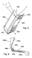
- the distributor flap 3 has three individual sections 3SE, 3SE and 3ME, in each case the outer axis 3SE associated with one of the air ducts SE for regulating the side defroster by an angle ⁇ with respect to the central section 3ME, which corresponds to the air duct ME assigned to control the windshield defrosting, is arranged twisted (see FIGS. 5 and 6 ).
- the angle ⁇ is preferably 5 ° to 25 °, in the present case about 20 °, so that each of the outer side defrosting sections 3SE of the distributor flap 3 releases the corresponding outlet opening to the air channel SE faster than the further middle and significantly larger section 3ME, which is assigned to the windscreen defrosting and thus the air channel SM.
- transition areas are arranged in the radial direction. These serve, inter alia, the stiffening of the distributor flap.
- a distribution flap position within the angle ⁇ is shown - in contrast to the middle, the windshield defroster associated area, ie the section 3ME - in the respective outer region of the distributor door 3, the cross section between the air duct housing 2 and distributor flap 3 already formed extended, which by the angular offset (angle ⁇ ) of the distributor door 3 yet is amplified, so that even at a low defrost position of the distributor flap 3, a relatively large air flow for the side defroster is available, while the windshield in the corresponding distributor flap position only a relatively small air flow is supplied.
- the portion 3ME has a slightly smaller radial extent than the two outer portions 3SE.
- the sections 3ME and 3SE have a first, in the radial direction with respect to the pivot axis extending inner region 3MEi and 3SEi, wherein the angular offset by the angle ⁇ is already provided in this area.
- sections 3SE and 3ME are angled at an angle of about 135 ° such that a substantial portion of sections 3ME and 3SE (exterior 3MEa and 3SEa), presently about four fifths of the total "radial" extent, do not extend in the radial direction with respect to the pivot axis (see Fig. 6 ).
- the outer axis portions 3SE in the swinging axis longitudinal direction each have a width of about one fifth of the width of the middle portion 3ME.
- the outermost region of the middle outer region 3MEa seen in the radial direction is also bent slightly curved, as in particular from Fig. 6 can be seen, whereby the flow path of the air is blocked over a slightly larger angular range (see Fig. 3 ).
- the distributor flap 3 also has three sections 3SD and 3MD for controlling the air supply of the side and center nozzles, which release the openings of the corresponding air channels SD and MD or completely or partially close.
- the middle portion 3MD extends in the radial direction with respect to the distributor flap pivot axis.
- the angle to the interior 3MEi is presently about 135 °.
- the lateral sections 3SD are - formed angled according to the sections 3SE and 3ME, wherein the respective inner area 3SDi extends approximately in extension of the inner areas 3SEi (see Fig. 6 ).
- the outside area 3SEa extends parallel to the middle section 3MD, resulting in an offset V of the sections.
- the offset V is usually between 2 and 10 mm, in this case 5 mm.
- ribs 6 are arranged on one flap surface each. How out Fig. 5 it can be seen, in each case two ribs 6 are arranged on the sections 3SD, which have a trapezoidal course, wherein the base is formed by the shaft region of the distributor flap 3. In the section 3MD on the ribs 6 of the sections 3SD facing flap surface a plurality, in the present case six, ribs 6 are arranged, which extend in the radial direction to the outside and have a triangular course of their height.
- the assembly of the distributor flap 3 in the air guide housing 2 is, as in the FIGS. 8 and 9 shown, easily possible if the air duct housing 2 is formed divided in the middle, and are inserted together with the distributor flap 3 in one of the halves, the halves and fixed together.
- Fig. 10 shows a section along by an air conditioner according to a variant of the embodiment described above, wherein the distributor flaps 3 and the releasable by the distributor flap 3 cross sections in the air guide housing 2 correspond to each other, so that the distributor flap 3 as well as their function is not described in detail.
- a mixing chamber 4 from which branches off a plurality of air channels.
- the regulation of the air distribution to the front area is done by means of said distributor flap 3 and a footwell flap 5, which regulates the inlet opening to the air channel F to the front footwell. How out Fig.
- the distributor flap 3 closes the air duct MD completely when the operating position 100% defrosting operation, as shown, is provided. In this operating position, moreover, the air channel F to the front footwell as well as the air duct FF to the rear area is closed, so that essentially all the air is available for defrosting the front and side windows.
- a small opening to the side nozzles is open due to the offset of the distributor flap 3, so that a (small) air flow flows to the side nozzles, which supports the defrosting of the side nozzles.
Landscapes
- Physics & Mathematics (AREA)
- Thermal Sciences (AREA)
- Engineering & Computer Science (AREA)
- Mechanical Engineering (AREA)
- Air-Conditioning For Vehicles (AREA)
Claims (8)
- Carter de guidage d'air, en particulier pour un système de climatisation (1) d'un véhicule automobile, comprenant au moins un volet répartiteur (3) disposé dans le carter de guidage d'air (2) en pouvant pivoter autour d'un axe de pivotement, volet répartiteur qui régule la répartition d'air à plusieurs conduits d'air (ME, SE, MD, SD) qui partent du carter de guidage d'air (2), où au moins l'un des conduits d'air (SE) sert au dégivrage des vitres latérales, au moins l'un des conduits d'air (ME) sert au dégivrage du pare-brise, un conduit d'air servant à la répartition d'air aux buses centrales (MD) et deux conduits d'air servant à la répartition d'air aux buses latérales (SD) où, dans chaque position de fonctionnement du volet répartiteur (3) suivant laquelle de l'air chaud peut être fourni à l'habitacle du véhicule, le volet répartiteur (3) libère au moins une ouverture minimale donnant sur le ou les conduits d'air (SE) servant au dégivrage des vitres latérales, et le volet répartiteur (3) est un volet papillon où les ailettes sont disposées, les unes par rapport aux autres, suivant un angle de moins de 180°, en particulier de moins de 120°, et le volet répartiteur (3) présente certaines parties (3MD, 3SD, 3ME, 3SE) qui sont associées, respectivement, au conduit d'air (SE) servant à la régulation du dégivrage des vitres latérales, au conduit d'air (ME) servant à la régulation du dégivrage du pare-brise, au conduit d'air (MD) menant à la buse centrale et aux conduits d'air (SD) menant aux buses latérales.
- Carter de guidage d'air selon la revendication 1, caractérisé en ce que l'ouverture du volet répartiteur donnant sur le ou les conduits d'air (SE) servant au dégivrage des vitres latérales est configurée de manière telle, qu'au moins dans des positions de fonctionnement réglées sur "chaud", une quantité de 5 % à 10 % du débit d'air total régulé par le volet répartiteur (3) soit dirigée à travers les conduits d'air (SE) servant au dégivrage des vitres latérales.
- Carter de guidage d'air selon l'une ou l'autre des revendications précédentes, caractérisé en ce que le volet répartiteur (3), vu dans le sens de la longueur de l'axe de pivotement du volet répartiteur (3), présente différentes parties (3ME, 3SE), où la partie (3SE), qui est associée au conduit d'air (SE) servant à la régulation du dégivrage des vitres latérales, est disposée en étant déplacée en torsion, d'un angle (β), par rapport à la partie (3ME) qui est associée au conduit d'air (ME) servant à la régulation du dégivrage du pare-brise.
- Carter de guidage d'air selon la revendication 3, caractérisé en ce que l'angle (β) est compris entre 5° et 25°, en particulier entre 10° et 20°.
- Carter de guidage d'air selon l'une quelconque des revendications précédentes, caractérisé en ce que le volet répartiteur (3), vu dans le sens de la longueur de l'axe de pivotement du volet répartiteur (3), présente différentes parties (3MD, 3SD), où la partie (3SD), qui est associée au conduit d'air (SD) menant à la buse latérale, est disposée en étant décalée, en particulier décalée de façon parallèle, d'un décalage (V), par rapport à la partie (3MD) qui est associée au conduit d'air (MD) menant à la buse centrale.
- Carter de guidage d'air selon la revendication 5, caractérisé en ce que le décalage (V) est de 2 mm à 10 mm, en particulier de 5 ± 3 mm.
- Carter de guidage d'air selon l'une quelconque des revendications précédentes, caractérisé en ce que la partie (3SE) qui est associée au conduit d'air (SE) servant à la régulation du dégivrage des vitres latérales est, vue dans le sens de la longueur du volet répartiteur (3), configurée en étant plus courte que la partie (3SD) qui est associée au conduit d'air (SD) menant à la vitre latérale, et / ou en ce que la partie (3ME) qui est associée au conduit d'air (ME) servant à la régulation du dégivrage du pare-brise est, vue dans le sens de la longueur du volet répartiteur (3), configurée en étant plus longue que la partie (3MD) qui est associée au conduit d'air (MD) menant à la buse centrale.
- Carter de guidage d'air selon l'une quelconque des revendications précédentes, caractérisé en ce que le volet répartiteur (3) prévoit une ventilation forcée à travers la buse latérale (SD).
Priority Applications (3)
| Application Number | Priority Date | Filing Date | Title |
|---|---|---|---|
| DE502006006859T DE502006006859D1 (de) | 2006-09-19 | 2006-09-19 | Luftführungsgehäuse, insbesondere für eine Kraftfahrzeug-Klimaanlage, mit einer Verteilerklappe und Verfahren zur Regelung einer derartigen Verteilerklappe |
| EP06291485A EP1902876B1 (fr) | 2006-09-19 | 2006-09-19 | Boîtier de distribution d'air, en particulier pour une climatisation de véhicule, le boîtier comprenant une vanne de distribution et un procédé de contrôle d'une telle vanne de distribution |
| KR1020070094703A KR101465792B1 (ko) | 2006-09-19 | 2007-09-18 | 자동차의 공기 조화 장치용 공기 분배 케이스 |
Applications Claiming Priority (1)
| Application Number | Priority Date | Filing Date | Title |
|---|---|---|---|
| EP06291485A EP1902876B1 (fr) | 2006-09-19 | 2006-09-19 | Boîtier de distribution d'air, en particulier pour une climatisation de véhicule, le boîtier comprenant une vanne de distribution et un procédé de contrôle d'une telle vanne de distribution |
Publications (2)
| Publication Number | Publication Date |
|---|---|
| EP1902876A1 EP1902876A1 (fr) | 2008-03-26 |
| EP1902876B1 true EP1902876B1 (fr) | 2010-04-28 |
Family
ID=37496525
Family Applications (1)
| Application Number | Title | Priority Date | Filing Date |
|---|---|---|---|
| EP06291485A Not-in-force EP1902876B1 (fr) | 2006-09-19 | 2006-09-19 | Boîtier de distribution d'air, en particulier pour une climatisation de véhicule, le boîtier comprenant une vanne de distribution et un procédé de contrôle d'une telle vanne de distribution |
Country Status (3)
| Country | Link |
|---|---|
| EP (1) | EP1902876B1 (fr) |
| KR (1) | KR101465792B1 (fr) |
| DE (1) | DE502006006859D1 (fr) |
Cited By (8)
| Publication number | Priority date | Publication date | Assignee | Title |
|---|---|---|---|---|
| US8925836B2 (en) | 2008-10-29 | 2015-01-06 | Sata Gmbh & Co. Kg | Gravity cup for a paint sprayer |
| USD740393S1 (en) | 2013-09-27 | 2015-10-06 | Sata Gmbh & Co. Kg | Paint spray gun |
| US9327301B2 (en) | 2008-03-12 | 2016-05-03 | Jeffrey D. Fox | Disposable spray gun cartridge |
| USD758537S1 (en) | 2014-07-31 | 2016-06-07 | Sata Gmbh & Co. Kg | Paint spray gun rear portion |
| US9409197B2 (en) | 2013-12-18 | 2016-08-09 | Sata Gmbh & Co. Kg | Air nozzle closure for a spray gun |
| USD768820S1 (en) | 2014-09-03 | 2016-10-11 | Sata Gmbh & Co. Kg | Paint spray gun with pattern |
| USD770593S1 (en) | 2014-07-31 | 2016-11-01 | Sata Gmbh & Co. Kg | Paint spray gun |
| US9533317B2 (en) | 2009-07-08 | 2017-01-03 | Sata Gmbh & Co. Kg | Paint spray gun |
Families Citing this family (22)
| Publication number | Priority date | Publication date | Assignee | Title |
|---|---|---|---|---|
| DE502007000825D1 (de) | 2006-12-05 | 2009-07-16 | Sata Gmbh & Co Kg | Belüftung für den Fließbecher einer Farbspritzpistole |
| KR101484707B1 (ko) * | 2008-07-07 | 2015-01-21 | 한라비스테온공조 주식회사 | 차량용 공조장치 |
| BRPI0900514A2 (pt) * | 2009-03-06 | 2010-12-14 | Valeo Sist S Automotivos Ltda Divisao Climatizacao | aparelho de ventilaÇço, aquecimento e/ou condicionamento do habitÁculo de um veÍculo automotivo |
| DE202010007355U1 (de) | 2010-05-28 | 2011-10-20 | Sata Gmbh & Co. Kg | Düsenkopf für eine Spritzvorrichtung |
| EP2646166B1 (fr) | 2010-12-02 | 2018-11-07 | SATA GmbH & Co. KG | Pistolet de pulvérisation et accessoire |
| CN103517765B (zh) | 2011-06-30 | 2017-09-12 | 萨塔有限两合公司 | 易清洗的喷枪、用于喷枪的附件及安装和拆卸方法 |
| KR101406651B1 (ko) | 2012-11-12 | 2014-06-13 | 현대자동차주식회사 | 차량의 공조장치 |
| DE102013104461B4 (de) * | 2013-05-02 | 2022-06-09 | Denso Automotive Deutschland Gmbh | Klimatisierungseinrichtung für ein Kraftfahrzeug |
| CN110560285B (zh) | 2014-07-31 | 2021-05-18 | 萨塔有限两合公司 | 喷枪及其制造方法 |
| US20170297413A9 (en) * | 2015-03-25 | 2017-10-19 | Denso International America, Inc. | Automotive hvac system |
| DE102015006484A1 (de) | 2015-05-22 | 2016-11-24 | Sata Gmbh & Co. Kg | Düsenanordnung für eine Spritzpistole, insbesondere Farbspritzpistole und Spritzpistole, insbesondere Farbspritzpistole |
| DE102015016474A1 (de) | 2015-12-21 | 2017-06-22 | Sata Gmbh & Co. Kg | Luftkappe und Düsenanordnung für eine Spritzpistole und Spritzpistole |
| CN205966208U (zh) | 2016-08-19 | 2017-02-22 | 萨塔有限两合公司 | 风帽组件以及喷枪 |
| CN205995666U (zh) | 2016-08-19 | 2017-03-08 | 萨塔有限两合公司 | 喷枪及其扳机 |
| DE102018202169A1 (de) * | 2018-02-13 | 2019-08-14 | Mahle International Gmbh | Luftklappe und ein Verfahren zum Herstellen der Luftklappe |
| DE102018118737A1 (de) | 2018-08-01 | 2020-02-06 | Sata Gmbh & Co. Kg | Düse für eine Spritzpistole, Düsensatz für eine Spritzpistole, Spritzpistolen und Verfahren zur Herstellung einer Düse für eine Spritzpistole |
| DE102018118738A1 (de) | 2018-08-01 | 2020-02-06 | Sata Gmbh & Co. Kg | Grundkörper für eine Spritzpistole, Spritzpistolen, Spritzpistolen-Set, Verfahren zur Herstellung eines Grundkörpers für eine Spritzpistole und Verfahren zum Umrüsten einer Spritzpistole |
| DE112018007865A5 (de) | 2018-08-01 | 2021-07-15 | Sata Gmbh & Co. Kg | Düsensatz für eine Spritzpistole, Spritzpistolensystem, Verfahren zum Ausgestalten eines Düsen-Moduls, Verfahren zur Auswahl eines Düsen-Moduls aus einem Düsensatz für eine Lackieraufgabe, Auswahlsystem und Computerprogrammprodukt |
| DE102018122004A1 (de) | 2018-09-10 | 2020-03-12 | Sata Gmbh & Co. Kg | Lackierpistole, Materialauftragssystem und Verfahren zu dessen Betrieb |
| DE102020106172A1 (de) | 2020-03-06 | 2021-09-09 | Sata Gmbh & Co. Kg | Spritzpistole, insbesondere druckluftzerstäubende Farbspritzpistole, insbesondere handgeführte druckluftzerstäubende Farbspritzpistole |
| DE102020123769A1 (de) | 2020-09-11 | 2022-03-17 | Sata Gmbh & Co. Kg | Dichtelement zum Abdichten eines Übergangs zwischen einem Grundkörper einer Spritzpistole und einem Anbauteil einer Spritzpistole, Anbauteil, insbesondere Farbdüsenanordnung, für eine Spritzpistole und Spritzpistole, insbesondere Farbspritzpistole |
| KR20230167602A (ko) | 2022-06-02 | 2023-12-11 | 차윤원 | 차량용 공기 분배기 |
Family Cites Families (6)
| Publication number | Priority date | Publication date | Assignee | Title |
|---|---|---|---|---|
| FR2703304B1 (fr) * | 1993-03-31 | 1995-06-23 | Valeo Thermique Habitacle | Boitier de distribution pour une installation de chauffage-ventilation de l'habitacle d'un vehicule automobile. |
| FR2717127B1 (fr) * | 1994-03-11 | 1996-07-05 | Valeo Thermique Habitacle | Dispositif de chauffage pour véhicule avec dégivrage des vitres latérales. |
| FR2789017B1 (fr) * | 1999-01-29 | 2001-06-08 | Valeo Climatisation | Dispositif de distribution d'un air d'aeration dans l'habitacle d'un vehicule automobile |
| FR2778151B1 (fr) * | 1998-04-30 | 2000-06-30 | Valeo Climatisation | Dispositif repartiteur d'un flux d'air dans un habitacle, notamment d'un vehicule automobile |
| JP3937626B2 (ja) * | 1999-01-28 | 2007-06-27 | 株式会社デンソー | 車両用空調装置 |
| JP4015454B2 (ja) * | 2002-03-28 | 2007-11-28 | カルソニックカンセイ株式会社 | 車両用空調装置 |
-
2006
- 2006-09-19 EP EP06291485A patent/EP1902876B1/fr not_active Not-in-force
- 2006-09-19 DE DE502006006859T patent/DE502006006859D1/de active Active
-
2007
- 2007-09-18 KR KR1020070094703A patent/KR101465792B1/ko not_active Expired - Fee Related
Cited By (9)
| Publication number | Priority date | Publication date | Assignee | Title |
|---|---|---|---|---|
| US9327301B2 (en) | 2008-03-12 | 2016-05-03 | Jeffrey D. Fox | Disposable spray gun cartridge |
| US8925836B2 (en) | 2008-10-29 | 2015-01-06 | Sata Gmbh & Co. Kg | Gravity cup for a paint sprayer |
| US9533317B2 (en) | 2009-07-08 | 2017-01-03 | Sata Gmbh & Co. Kg | Paint spray gun |
| USD740393S1 (en) | 2013-09-27 | 2015-10-06 | Sata Gmbh & Co. Kg | Paint spray gun |
| US9409197B2 (en) | 2013-12-18 | 2016-08-09 | Sata Gmbh & Co. Kg | Air nozzle closure for a spray gun |
| USD758537S1 (en) | 2014-07-31 | 2016-06-07 | Sata Gmbh & Co. Kg | Paint spray gun rear portion |
| USD770593S1 (en) | 2014-07-31 | 2016-11-01 | Sata Gmbh & Co. Kg | Paint spray gun |
| USD798419S1 (en) | 2014-07-31 | 2017-09-26 | Sata Gmbh & Co. Kg | Paint spray gun |
| USD768820S1 (en) | 2014-09-03 | 2016-10-11 | Sata Gmbh & Co. Kg | Paint spray gun with pattern |
Also Published As
| Publication number | Publication date |
|---|---|
| KR20080026056A (ko) | 2008-03-24 |
| DE502006006859D1 (de) | 2010-06-10 |
| KR101465792B1 (ko) | 2014-11-26 |
| EP1902876A1 (fr) | 2008-03-26 |
Similar Documents
| Publication | Publication Date | Title |
|---|---|---|
| EP1902876B1 (fr) | Boîtier de distribution d'air, en particulier pour une climatisation de véhicule, le boîtier comprenant une vanne de distribution et un procédé de contrôle d'une telle vanne de distribution | |
| EP0461421B1 (fr) | Dispositif de chauffage et ventilation pour véhicules automobiles | |
| DE102015110481A1 (de) | Vorrichtung zum Beheizen, Belüften und/oder Klimatisieren eines Fahrzeuginnenraums | |
| DE19922324C1 (de) | Heizungs- oder Klimaanlage für eine Fahrgastzelle eines Fahrzeugs | |
| EP2062763B1 (fr) | Buse, notamment pour un véhicule | |
| EP1526977B1 (fr) | Boitier de climatisation | |
| EP2015948B1 (fr) | Installation de climatisation pour vehicule automobile | |
| EP1641642B1 (fr) | Systeme de climatisation de vehicule a moteur | |
| EP2072297B1 (fr) | Clapet, notamment pour un canal d'aération | |
| EP1930191B1 (fr) | Dispositif de chauffage et/ou de climatisation d'un véhicule avec un volet de mixage et de distribution d'air | |
| EP2011675B1 (fr) | Climatiseur | |
| DE102007013432B4 (de) | Warmluftkanal für ein Klimagerät eines Kraftfahrzeuges | |
| EP2048009B1 (fr) | Agencement de climatisation de véhicule automobile | |
| EP2174809B1 (fr) | Climatisation de véhicule | |
| DE10261036A1 (de) | Klimagehäuse | |
| EP1319537B1 (fr) | Installation de chauffage ou de climatisation pour véhicule à moteur | |
| EP1522434B1 (fr) | Climatisation, en particulier climatisation de véhicule | |
| EP2011676B1 (fr) | Climatiseur | |
| DE19519114B4 (de) | Heizungs- und Klimaanlage für Innenräume von Fahrzeugen | |
| EP1738941A1 (fr) | Dispositif de climatisation pour véhicule | |
| DE102018121512B4 (de) | Klimagerät für ein Kraftfahrzeug | |
| DE19951102C1 (de) | Klimaanlage für eine Fahrgastzelle eines Fahrzeugs | |
| EP1843908B1 (fr) | Systeme de climatisation pour un vehicule a moteur | |
| EP1479545B1 (fr) | Climatisation, en particulier pour véhicule, et méthode de climatisation | |
| DE19730434B4 (de) | Vorrichtung zur Heizung und Belüftung des Fahrgastraums eines Kraftfahrzeugs |
Legal Events
| Date | Code | Title | Description |
|---|---|---|---|
| PUAI | Public reference made under article 153(3) epc to a published international application that has entered the european phase |
Free format text: ORIGINAL CODE: 0009012 |
|
| AK | Designated contracting states |
Kind code of ref document: A1 Designated state(s): AT BE BG CH CY CZ DE DK EE ES FI FR GB GR HU IE IS IT LI LT LU LV MC NL PL PT RO SE SI SK TR |
|
| AX | Request for extension of the european patent |
Extension state: AL BA HR MK YU |
|
| 17P | Request for examination filed |
Effective date: 20080926 |
|
| 17Q | First examination report despatched |
Effective date: 20081023 |
|
| AKX | Designation fees paid |
Designated state(s): CZ DE FR IT SE |
|
| GRAP | Despatch of communication of intention to grant a patent |
Free format text: ORIGINAL CODE: EPIDOSNIGR1 |
|
| GRAS | Grant fee paid |
Free format text: ORIGINAL CODE: EPIDOSNIGR3 |
|
| GRAA | (expected) grant |
Free format text: ORIGINAL CODE: 0009210 |
|
| AK | Designated contracting states |
Kind code of ref document: B1 Designated state(s): CZ DE FR IT SE |
|
| REF | Corresponds to: |
Ref document number: 502006006859 Country of ref document: DE Date of ref document: 20100610 Kind code of ref document: P |
|
| PG25 | Lapsed in a contracting state [announced via postgrant information from national office to epo] |
Ref country code: SE Free format text: LAPSE BECAUSE OF FAILURE TO SUBMIT A TRANSLATION OF THE DESCRIPTION OR TO PAY THE FEE WITHIN THE PRESCRIBED TIME-LIMIT Effective date: 20100428 |
|
| PG25 | Lapsed in a contracting state [announced via postgrant information from national office to epo] |
Ref country code: CZ Free format text: LAPSE BECAUSE OF FAILURE TO SUBMIT A TRANSLATION OF THE DESCRIPTION OR TO PAY THE FEE WITHIN THE PRESCRIBED TIME-LIMIT Effective date: 20100428 |
|
| PLBE | No opposition filed within time limit |
Free format text: ORIGINAL CODE: 0009261 |
|
| STAA | Information on the status of an ep patent application or granted ep patent |
Free format text: STATUS: NO OPPOSITION FILED WITHIN TIME LIMIT |
|
| PG25 | Lapsed in a contracting state [announced via postgrant information from national office to epo] |
Ref country code: IT Free format text: LAPSE BECAUSE OF FAILURE TO SUBMIT A TRANSLATION OF THE DESCRIPTION OR TO PAY THE FEE WITHIN THE PRESCRIBED TIME-LIMIT Effective date: 20100428 |
|
| 26N | No opposition filed |
Effective date: 20110131 |
|
| PGFP | Annual fee paid to national office [announced via postgrant information from national office to epo] |
Ref country code: FR Payment date: 20110927 Year of fee payment: 6 |
|
| REG | Reference to a national code |
Ref country code: FR Ref legal event code: ST Effective date: 20130531 |
|
| PG25 | Lapsed in a contracting state [announced via postgrant information from national office to epo] |
Ref country code: FR Free format text: LAPSE BECAUSE OF NON-PAYMENT OF DUE FEES Effective date: 20121001 |
|
| REG | Reference to a national code |
Ref country code: DE Ref legal event code: R082 Ref document number: 502006006859 Country of ref document: DE Representative=s name: GRAUEL, ANDREAS, DIPL.-PHYS. DR. RER. NAT., DE Ref country code: DE Ref legal event code: R081 Ref document number: 502006006859 Country of ref document: DE Owner name: MAHLE INTERNATIONAL GMBH, DE Free format text: FORMER OWNER: BEHR FRANCE ROUFFACH S.A.S., ROUFFACH, FR |
|
| PGFP | Annual fee paid to national office [announced via postgrant information from national office to epo] |
Ref country code: DE Payment date: 20181001 Year of fee payment: 13 |
|
| REG | Reference to a national code |
Ref country code: DE Ref legal event code: R119 Ref document number: 502006006859 Country of ref document: DE |
|
| PG25 | Lapsed in a contracting state [announced via postgrant information from national office to epo] |
Ref country code: DE Free format text: LAPSE BECAUSE OF NON-PAYMENT OF DUE FEES Effective date: 20200401 |