EP1902900A2 - Système vidéo pour un véhicule et procédé de vérification du fonctionnement du système vidéo - Google Patents
Système vidéo pour un véhicule et procédé de vérification du fonctionnement du système vidéo Download PDFInfo
- Publication number
- EP1902900A2 EP1902900A2 EP07114084A EP07114084A EP1902900A2 EP 1902900 A2 EP1902900 A2 EP 1902900A2 EP 07114084 A EP07114084 A EP 07114084A EP 07114084 A EP07114084 A EP 07114084A EP 1902900 A2 EP1902900 A2 EP 1902900A2
- Authority
- EP
- European Patent Office
- Prior art keywords
- camera
- video system
- video
- image signals
- vehicle
- Prior art date
- Legal status (The legal status is an assumption and is not a legal conclusion. Google has not performed a legal analysis and makes no representation as to the accuracy of the status listed.)
- Withdrawn
Links
Images



Classifications
-
- H—ELECTRICITY
- H04—ELECTRIC COMMUNICATION TECHNIQUE
- H04N—PICTORIAL COMMUNICATION, e.g. TELEVISION
- H04N17/00—Diagnosis, testing or measuring for television systems or their details
- H04N17/002—Diagnosis, testing or measuring for television systems or their details for television cameras
-
- B—PERFORMING OPERATIONS; TRANSPORTING
- B60—VEHICLES IN GENERAL
- B60R—VEHICLES, VEHICLE FITTINGS, OR VEHICLE PARTS, NOT OTHERWISE PROVIDED FOR
- B60R2300/00—Details of viewing arrangements using cameras and displays, specially adapted for use in a vehicle
- B60R2300/40—Details of viewing arrangements using cameras and displays, specially adapted for use in a vehicle characterised by the details of the power supply or the coupling to vehicle components
- B60R2300/402—Image calibration
Definitions
- the invention relates to a video system for a vehicle and a method for functional testing of the video system.
- Video cameras in vehicles are increasingly being used for driver assistance systems.
- the video camera system is generally used to represent the vehicle environment.
- electrochromic systems are still known in which an electrochromic gel layer is applied to the glass sheet, the degree of which varies depending on an applied voltage. As a result, the dimming factor of the mirror can be changed. Such a measure is particularly helpful if the headlights of subsequent vehicles interfere with their dazzling effect.
- first photocell which measures the light intensity in the vehicle apron
- second photocell which measures the light intensity of the glare.
- An electronic control system compares both light levels. The higher the difference between the two light intensities, the greater the glare effect. By comparing it can be achieved that the mirrors only respond to glare from subsequent vehicles and not, for example, to strong sunlight.
- the DE 102 01 520 A1 describes a method and a device for image defect detection and display in image recording systems, in particular in motor vehicles. Thereby, a self-diagnosis of the cameras for video surveillance systems can be performed, which relate to the detection of failures of electronic components or the image sensor itself, wherein a comparison with a prestored reference value is performed and upon detection of an image defect, an error signal is output.
- the invention is based on the idea of carrying out a self-monitoring of the camera system in which different settings of the degree of tinting or of the transmission value of a variably transmitting device (VLP) are set and images are taken in each case by the video camera.
- VLP variably transmitting device
- the image signals can thus be subsequently evaluated as a function of the respective degree of tinting, in order to draw conclusions about the functionality or possible errors.
- the invention can be detected as a possible source of error optical coverage or obscuring the transparent pane of the vehicle by an object, contamination or fogging, furthermore a defect of the camera control or the video camera and defocusing or misalignment or incorrect positioning of the video camera.
- variable-transmissive layer can additionally be illuminated from the inside of the camera housing, for which purpose an LED can be provided in the camera housing as the light source. This can be between a mistake in the camera or camera control and a cover or cover from the outside be differentiated. If no change is detected in the image signal or in the set camera parameters of the camera control when changing the degree of tinting, this could initially be due to a complete occlusion of the vehicle window or a faulty camera or camera control. Subsequent execution of a further test series with complete darkening of the electrochromatic layer and illumination from the inside at different illumination intensities or intensity values can differentiate between these two sources of error.
- video-based driver assistance systems can be realized in which the image signals generated by the video camera not only acting, but also warning or even intervene in the vehicle dynamics.
- the different monitoring methods can be carried out automatically. Upon detection of a source of error they can be repeated automatically and, if necessary, complicated additional procedures can be carried out. Upon detection of an error, a corresponding error signal can be output, which indicates to the driver the lack of functionality of his camera system.
- a video camera, the electrochromic layer and the control device are generally already present, so that only if necessary in addition, the light source is to be provided for the interior lighting of the electrochromatic layer.
- a video system 1 according to the invention in a vehicle has, according to FIG. 1, a video camera 2, which is arranged behind a windshield 3 of the vehicle and detects an environment of the vehicle, in particular the roadway area in front of the vehicle.
- the video camera 2 has a camera body 4 that connects closely to the windscreen 3.
- the area of the windshield 3, which closes the camera body 4 forward, is provided on its front or rear side with an electrochromic layer 5, which steplessly obscures with a degree of tinting from 0 to 100% on a first control signal S1 output by a control device 6 can be.
- the windshield 3 may also be formed electrochromic outside its area covering the camera body 4; however, for the following self-monitoring procedure, these other areas are not darkened.
- the electrochromic layer 5 is mounted on a support as a variably transparent device between the video camera 2 and the windshield arranged.
- the video camera 2 outputs image signals S4 to the controller 6; the controller 6 controls with second control signals S2 an LED 7 provided in the camera body 4 directed to the area of the windshield 3 inside the camera body 4, and further outputs third control signals S3 to the video camera 2 for setting various camera parameters, e.g. B. the exposure time and the aperture (aperture).
- the control device 6 is reproduced here as a function block; it may accordingly also be multi-part, i.
- Various control units may be provided for outputting the first control signals 1 for dimming or for varying the degree of tinting T of the electrochromic layer 5 and for outputting the control signals S2 and S3.
- the controller 6 exchanges over z. B. the CAN bus signals S5 with other in-vehicle facilities; In this case, it can use the image signals S4 or data obtained from image signals S4, z. B. also warning signals or error signals S6 to a driver assistance system or a vehicle dynamics control output and is controlled by another control device for starting the self-monitoring method accordingly.
- the electrochromatic layer 5 may be e.g. are formed by a gel layer 5, the degree of tinting or transmission value can be varied continuously. In this case serves as a control signal S1 applied to the electrochromic layer 5 electrical voltage, which is known in the art and will not be further elaborated here.
- a self-monitoring method is initiated, for example, when starting the vehicle via a corresponding control signal S5, as shown in step St1 of the flowchart of FIG. 4.
- the control device 6 in this case leads successively one or more of the following test methods by:
- the controller 6 varies the degree of tinting T shown in Fig. 2 within a predetermined range, e.g. between 0 and 100%; which is shown as step St2 of FIG.
- step St3 it acquires image signals S4 of the video camera 2 for each degree of toning T, calculates therefrom the mean gray value of the brightness, and in step St4 controls a manipulated variable by means of the control signals S3.
- a camera parameter of the video camera 2 e.g. the exposure time or aperture number (aperture opening) to control the constant mean gray level G1 of the horizontal line in FIG.
- the steps St2, St3, St4 thus describe a loop.
- the image signals S4 are thus recorded without activation of the electrochromatic layer 5 and the camera parameters are read out.
- the degree of tinting of the electrochromic layer 5 is darkened gradually, so that less light reaches the internal imager of the video camera 2.
- the control of the video camera 2 together with its control device 6 reacts to these changed conditions, for example by an extension of the exposure time or enlargement of the aperture.
- the camera parameters are read out accordingly and compared in step St5 with the parameters of the previously recorded situation. If a change with the expected behavior is to be proven, then the test has passed successfully and can be ended in step St6.
- T2 the maximum exposure time of camera 2 (in driver assistance systems, for example, 40 ms) or maximum aperture opening is reached, so that no regulation of this parameter can take place more and the gray value G falls below the set average gray value G1.
- the image thus becomes darker and buckles down in Fig. 2.
- the average gray value G decreases as the degree of tinting increases, which is shown in curve c.
- the field of view of the camera can be completely by an object, for.
- a leaf may be obscured, or the video camera 2 may not provide an image, i. be defect.
- a warning message may be generated, i. a warning signal S6 are output.
- the gray value G can also be changed so that FIG. 2 does not regulate to a fixed mean gray value G but, for example, FIG. a sloping or rising line.
- This test method is particularly relevant if, in the first test method described under 1. an error according to curve b is detected, a more precise differentiation is not yet possible.
- the LED 7 is in step St8 via control signals S2 is subsequently controlled in such a way that it generates different illuminances in which images are taken by the camera 2 in step St9 and the image signals S4 obtained in the loop St7, St8, St9 and the camera parameters of the control are evaluated by the control device 6 in step St10 , If more light is output by the LED 7, the camera 2 becomes brighter with the camera 2 functioning and the camera control responds accordingly with, for example, a shortening of the exposure time or reduction of the aperture.
- This test can thus be used to determine whether the camera 2 is functional and furthermore the camera control generally works under defined conditions. Since the windshield 3 is completely darkened, impairments of the camera field of view, for example by a sheet on the windshield 3, are not included in the measurement and can not be detected either.
- a faulty video system or camera system can thus be differentiated from a darkening of the camera field of view by the test method described under 2. If both tests, i. E. the first test method with increasing T level T and the second test method with decreasing light intensity (and complete darkening) the same characteristic, there is an error in the video system. If the characteristic is different, the fault is present on the windscreen.
- the mean gray value G decreases linearly with increasing degree of tinting. In this way it can thus be checked whether the video camera 2 (or its imager) and the electrochromatic layer 5 are working properly and whether the windshield 3 is covered by an object. If the curve b is determined in this test, again by a test according to the second test method, but with constant camera parameters, between a mask and a defective video system.
- the camera 2 is mounted in the vehicle in a particular mounting position and calibrated for that position, i. their position is determined with respect to a reference point and a reference axis of the vehicle.
- the assistance system only works properly if the position of the camera 2 does not change.
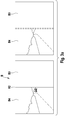
- a partial region of the electrochromatic layer 5, e.g. an upper partial area 5.1 is completely darkened and the lower partial area 5.2 is completely transparent, so that according to the left-hand illustration of FIG. 3b in the correct position of the camera 2 in the image B the upper image area B1 is dark and the lower image area B2 is light, one image edge K1 should be at a predetermined location of the image B. If the camera shifts 2, z. B. According to the right-hand illustration of Fig. 3b, the image edge K1 at a different position or at a different angle than before.
- the proper position of the image edge K1 is to be determined once at the beginning after installation in order to use it as a reference below.
- This fourth test can be done at the beginning of the self-examination procedure. If it is determined in the test that the installation position has not changed, then the driver assistance system can be started. If a change is detected, it can be checked whether this change is within specified tolerance values. If the change is within the tolerance values, advantageously a warning is written to an error memory. If it is outside the tolerance values, for example, a warning signal S6 or error signal can be output, in which the driver is asked to visit the nearest specialist workshop to have the error corrected.
- the focus of the camera 2 is factory set so that a certain distance range is sharply displayed.
- the set camera focus can be adjusted, which is checked according to the invention.
- the control device 6 subsequently evaluates the recorded image signals S4 with image processing, so that a measure or an evaluation number for the sharpness of this edge K2 can be generated.
- This measure or this evaluation number is to be initially determined once as a reference value at the beginning after installation, whereby this can be done automatically as part of an initialization procedure.
- this test procedure is run through, in which the partial area B3 is completely darkened and the position of the edge K2 is determined and compared with the reference value. If a significant deviation is detected, this may indicate that the camera focus has shifted and the camera is defocused. Another cause could be e.g. be a contamination of the lens or an internally misted disc 3. Upon detection of an error again an error signal S6 is output.
Landscapes
- Engineering & Computer Science (AREA)
- Health & Medical Sciences (AREA)
- Biomedical Technology (AREA)
- General Health & Medical Sciences (AREA)
- Multimedia (AREA)
- Signal Processing (AREA)
- Studio Devices (AREA)
- Testing, Inspecting, Measuring Of Stereoscopic Televisions And Televisions (AREA)
Applications Claiming Priority (1)
| Application Number | Priority Date | Filing Date | Title |
|---|---|---|---|
| DE102006044428A DE102006044428A1 (de) | 2006-09-21 | 2006-09-21 | Videosystem für ein Fahrzeug und Verfahren zur Funktionsüberprüfung des Videosystems |
Publications (2)
| Publication Number | Publication Date |
|---|---|
| EP1902900A2 true EP1902900A2 (fr) | 2008-03-26 |
| EP1902900A3 EP1902900A3 (fr) | 2011-03-23 |
Family
ID=38904845
Family Applications (1)
| Application Number | Title | Priority Date | Filing Date |
|---|---|---|---|
| EP07114084A Withdrawn EP1902900A3 (fr) | 2006-09-21 | 2007-08-09 | Système vidéo pour un véhicule et procédé de vérification du fonctionnement du système vidéo |
Country Status (2)
| Country | Link |
|---|---|
| EP (1) | EP1902900A3 (fr) |
| DE (1) | DE102006044428A1 (fr) |
Cited By (5)
| Publication number | Priority date | Publication date | Assignee | Title |
|---|---|---|---|---|
| WO2012017334A3 (fr) * | 2010-06-11 | 2012-11-15 | Conti Temic Microelectronic Gmbh | Système de caméra destiné à être utilisé dans des véhicules |
| EP2589513A1 (fr) * | 2011-11-03 | 2013-05-08 | Autoliv Development AB | Système de vision et procédé pour véhicule à moteur |
| EP2147844A3 (fr) * | 2008-07-22 | 2016-04-20 | Siemens Aktiengesellschaft | Dispositif de surveillance d'une zone d'espace, notamment dans l'environnement ou à l'intérieur d'un véhicule |
| WO2021183455A3 (fr) * | 2020-03-11 | 2022-02-10 | Moog Inc. | Système de caméra dans un test intégré de situation |
| CN114779838A (zh) * | 2022-06-20 | 2022-07-22 | 鲁冉光电(微山)有限公司 | 一种车载摄像头角度智能调节控制系统 |
Families Citing this family (4)
| Publication number | Priority date | Publication date | Assignee | Title |
|---|---|---|---|---|
| DE102009007840A1 (de) | 2009-02-06 | 2010-08-12 | Adc Automotive Distance Control Systems Gmbh | Verfahren zur Kalibrierung eines kamerabasierten Systems |
| US8605949B2 (en) | 2011-11-30 | 2013-12-10 | GM Global Technology Operations LLC | Vehicle-based imaging system function diagnosis and validation |
| DE102017219092B4 (de) * | 2017-10-25 | 2021-01-28 | Continental Automotive Gmbh | Verfahren zum Aufnehmen und Verarbeiten von Bildern einer Umgebung eines Fahrzeuges, Steuereinrichtung und Fahrzeug ausgestattet zur Durchführung eines derartigen Verfahrens sowie Computerprogrammprodukt |
| DE102018124530A1 (de) * | 2018-10-04 | 2020-04-09 | Rheinmetall Electronics Gmbh | Vorrichtung und Verfahren zur validierbaren Ausgabe von Bildern |
Family Cites Families (2)
| Publication number | Priority date | Publication date | Assignee | Title |
|---|---|---|---|---|
| DE19805000A1 (de) * | 1998-02-07 | 1999-08-12 | Opel Adam Ag | Optische Sensorvorrichtung für Kraftfahrzeuge |
| TW500967B (en) * | 2001-12-19 | 2002-09-01 | Acer Peripherals Inc | Automatic exposure function testing device of digital camera |
-
2006
- 2006-09-21 DE DE102006044428A patent/DE102006044428A1/de not_active Withdrawn
-
2007
- 2007-08-09 EP EP07114084A patent/EP1902900A3/fr not_active Withdrawn
Cited By (7)
| Publication number | Priority date | Publication date | Assignee | Title |
|---|---|---|---|---|
| EP2147844A3 (fr) * | 2008-07-22 | 2016-04-20 | Siemens Aktiengesellschaft | Dispositif de surveillance d'une zone d'espace, notamment dans l'environnement ou à l'intérieur d'un véhicule |
| EP2147844B1 (fr) | 2008-07-22 | 2017-12-13 | Siemens Aktiengesellschaft | Dispositif de surveillance d'une zone d'espace, notamment dans l'environnement ou à l'intérieur d'un véhicule |
| WO2012017334A3 (fr) * | 2010-06-11 | 2012-11-15 | Conti Temic Microelectronic Gmbh | Système de caméra destiné à être utilisé dans des véhicules |
| EP2589513A1 (fr) * | 2011-11-03 | 2013-05-08 | Autoliv Development AB | Système de vision et procédé pour véhicule à moteur |
| WO2021183455A3 (fr) * | 2020-03-11 | 2022-02-10 | Moog Inc. | Système de caméra dans un test intégré de situation |
| US12368839B2 (en) | 2020-03-11 | 2025-07-22 | Moog Inc. | Camera system in situation built-in-test |
| CN114779838A (zh) * | 2022-06-20 | 2022-07-22 | 鲁冉光电(微山)有限公司 | 一种车载摄像头角度智能调节控制系统 |
Also Published As
| Publication number | Publication date |
|---|---|
| DE102006044428A1 (de) | 2008-04-03 |
| EP1902900A3 (fr) | 2011-03-23 |
Similar Documents
| Publication | Publication Date | Title |
|---|---|---|
| EP1902900A2 (fr) | Système vidéo pour un véhicule et procédé de vérification du fonctionnement du système vidéo | |
| DE102008027194B4 (de) | Gesichtsbildaufnahmevorrichtung | |
| DE60316074T2 (de) | Aktives Nachtsichtsystem für ein Kraftfahrzeug | |
| DE102008042537B4 (de) | Verfahren zum Kalibrieren eines Bilderfassunssystems in einem Kraftfahrzeug und Bilderfassungssystem | |
| EP1214224B1 (fr) | Dispositif de capteurs automobiles pour detection de l'environnement | |
| WO1999026816A1 (fr) | Dispositif et procede pour la detection d'objets se trouvant sur un pare-brise | |
| WO2017190166A1 (fr) | Procédé permettant d'améliorer les conditions de luminosité du point de vue du conducteur d'un véhicule automobile | |
| DE10302671A1 (de) | Verfahren und Vorrichtung zur Einstellung eines Bildsensorsystems | |
| EP2583847A1 (fr) | Dispositif et procédé de réduction d'éblouissement | |
| DE102011017644A1 (de) | Verfahren zur Steuerung einer Scheinwerferanlage eines Fahrzeugs und Vorrichtung zur Ansteuerung einer Scheinwerferanlage eines Fahrzeugs | |
| DE102015014263A1 (de) | Verfahren und Vorrichtung zur fahrsituationsabhängigen Parametervariation bei einem fahrzeugseitigen Kamera-Monitor-System | |
| WO2017148620A1 (fr) | Procédé de fonctionnement d'un dispositif d'affichage et dispositif d'affichage | |
| DE102018207388A1 (de) | Verfahren und Vorrichtung zur Erzeugung eines Anzeigebildes in einem Kraftfahrzeug | |
| EP3084385B1 (fr) | Procédé et dispositif de détermination d'une orientation de faisceau de lumière d'un projecteur | |
| DE10339975B4 (de) | Abbildungsvorrichtung | |
| DE102016213066A1 (de) | Vorrichtung zur Fahrerbeobachtung | |
| DE102014013236B4 (de) | Prüfvorrichtung zum automatisierten Prüfen einer Funktionsfähigkeit eines Fahrzeugs sowie Verfahren zum Betreiben einer Prüfvorrichtung | |
| DE102008034166A1 (de) | Verfahren und Vorrichtung zum Emitteln einer geeigneten Lichtverteilung des durch mindestens einen Frontscheinwerfer eines Fahrzeugs abgestrahlten Lichts | |
| DE102012023126A1 (de) | Verfahren und Vorrichtung zum automatischen Kalibrieren zumindest eines Scheinwerfers eines Fahrzeugs | |
| EP4337487B1 (fr) | Procédé et dispositif pour faire fonctionner un système d'affichage de pare-brise à détection d'affichage couverte, et système d'affichage de pare-brise | |
| DE102019218450A1 (de) | Verfahren und Vorrichtung zur Bestimmung einer optischen Beeinträchtigung einer Kamera | |
| DE102012008736A1 (de) | System und Verfahren zur dynamischen Lichtstromfilterung | |
| DE102021213471A1 (de) | Kameraüberwachungssystem, das auf lichtmenge reagiert | |
| DE102017131074A1 (de) | Beleuchtungsvorrichtung für Fahrzeuge und Steuerverfahren | |
| DE102017211055A1 (de) | Verfahren und Vorrichtung zum Überprüfen der Scheinwerfereinstellung eines Fahrzeugs |
Legal Events
| Date | Code | Title | Description |
|---|---|---|---|
| PUAI | Public reference made under article 153(3) epc to a published international application that has entered the european phase |
Free format text: ORIGINAL CODE: 0009012 |
|
| AK | Designated contracting states |
Kind code of ref document: A2 Designated state(s): AT BE BG CH CY CZ DE DK EE ES FI FR GB GR HU IE IS IT LI LT LU LV MC MT NL PL PT RO SE SI SK TR |
|
| AX | Request for extension of the european patent |
Extension state: AL BA HR MK YU |
|
| PUAL | Search report despatched |
Free format text: ORIGINAL CODE: 0009013 |
|
| AK | Designated contracting states |
Kind code of ref document: A3 Designated state(s): AT BE BG CH CY CZ DE DK EE ES FI FR GB GR HU IE IS IT LI LT LU LV MC MT NL PL PT RO SE SI SK TR |
|
| AX | Request for extension of the european patent |
Extension state: AL BA HR MK RS |
|
| AKY | No designation fees paid | ||
| REG | Reference to a national code |
Ref country code: DE Ref legal event code: R108 |
|
| REG | Reference to a national code |
Ref country code: DE Ref legal event code: R108 Effective date: 20111130 |
|
| STAA | Information on the status of an ep patent application or granted ep patent |
Free format text: STATUS: THE APPLICATION IS DEEMED TO BE WITHDRAWN |
|
| 18D | Application deemed to be withdrawn |
Effective date: 20110924 |