EP1902946A1 - Leichtes Luftschiff, das mit perfektionierten Flügeln ausgestattet ist - Google Patents
Leichtes Luftschiff, das mit perfektionierten Flügeln ausgestattet ist Download PDFInfo
- Publication number
- EP1902946A1 EP1902946A1 EP07352005A EP07352005A EP1902946A1 EP 1902946 A1 EP1902946 A1 EP 1902946A1 EP 07352005 A EP07352005 A EP 07352005A EP 07352005 A EP07352005 A EP 07352005A EP 1902946 A1 EP1902946 A1 EP 1902946A1
- Authority
- EP
- European Patent Office
- Prior art keywords
- rigid
- extrados
- wing
- rods
- intrados
- Prior art date
- Legal status (The legal status is an assumption and is not a legal conclusion. Google has not performed a legal analysis and makes no representation as to the accuracy of the status listed.)
- Granted
Links
Images


Classifications
-
- B—PERFORMING OPERATIONS; TRANSPORTING
- B64—AIRCRAFT; AVIATION; COSMONAUTICS
- B64C—AEROPLANES; HELICOPTERS
- B64C3/00—Wings
- B64C3/18—Spars; Ribs; Stringers
- B64C3/187—Ribs
Definitions
- FIG. 1 shows a rigid frame 1 of a wing in plan view, comprising a leading edge beam 2, a beam 3 of FIG. trailing edge, rigid bars 4 connecting these two beams, and a triangulation assembly 5 consisting of crossed bars to stiffen the frame.
- the frame is covered with a flexible envelope 6 called "sock", as shown in Figure 2, defining the wing profile by means of rods 7 whose profile is predetermined and which are placed between the beam 2 edge 3 and the trailing edge beam 3 as shown in FIG. 3, which is a cross-sectional view of FIG. 2.
- a flexible envelope is here understood to mean a flexible film, a fabric, or the like, for example polyester fabric, fabric Trilam®, more commonly defining a known technique known as "tubes and canvases" when the rigid frame is wholly or partly tubular.
- the rigid structure of the aircraft in particular that of the wings, is composed of rigid metal tubes with a predetermined profile. Because of the specific structure of this type of light aircraft, it is here specified certain terminological concepts: the rigid upper and lower pressure rods, although not normally linked by a rigid connection directly to the edge beams. of attack and trailing edge, so not forming part of the rigid frame, can be considered by extension as participating in this rigid frame and thus as a constituent element thereof via the flexible envelope because of their participation in the definition of the wing profile.
- the wing profile is thus defined by means of the rigid frame combined with the flexible envelope and the rigid upper and lower pressure rods.
- the term "joining" used above with respect to rods and leading edge and trailing girders is specified here: it should be noted that the upper and lower shanks may not be directly connected. to the leading edge and trailing edge beams as explained above; indeed, their ends may be only close to the leading edge and trailing edge beams respectively and separated from them by a small distance, the connection between the upper and lower pressure rods and the edge beams. etching and trailing edge being constituted by the flexible envelope.
- the rigidity of the assembly is obtained on the one hand by the fact that the distance between the end of the rods and the leading edge and trailing edge beams is small, minimizing the relative movement of each with respect to others that could be consecutive to the flexibility of the envelope, and secondly by the tension to which the flexible envelope is subjected on the framework.
- spacers between the upper and lower pressure rods makes it possible to bind these two rods in a transverse plane of the wing, and thus to prevent any relative movement of the extrados rod relative to the rod. of intrados, so as to preserve the predetermined performance of the wing profile.
- the solution of a combination of the extrados and intrados rods with a spacer makes it possible to guarantee the lightness of the structure without compromising the principle of the wing profile obtained by combining a flexible envelope and a rigid structure, with the advantages it provides, namely lightness, simplicity of design, reliability, ease of assembly, disassembly, and repair.
- said flexible envelope comprises a plurality of housings in which are housed said plurality of rigid extrados rods and said plurality of rigid lower wing shanks, and said plurality of spacers is associated with said rods. rigid extrados and intrados via said flexible envelope.
- This feature makes it possible to apply the present invention to an aircraft of the prior art with support of the spacers on the wing profile rods, the flexible envelope being present between the spacer and the upper or lower rod. soffit.
- a spacer of said plurality of spacers is associated with said flexible envelope or with said rigid upper and lower pressure rods by a self-locking type connection, whose self-locking characteristic is ensured when said aircraft is in flight.
- This characteristic makes it possible to integrate the invention into the concept of a light aircraft with a rigid structure and a flexible envelope, by making the best use of the forces that come into play on the wing in flight, combined with the shape and rigidity of the aircraft. upper and lower pressure rods, to hold the spacers in place.
- said plurality of spacers is removably associated with said flexible envelope or with said rigid upper and lower pressure rods.
- This feature contributes to a quick and easy disassembly of the aircraft, and reduces the assembly time by using a simple connection to implement.
- the removable nature of the spacers makes it possible to envisage a rapid replacement, in part or in whole for a given aircraft, of a set of spacers by spacers of different dimensions, in order to modify the predetermined wing profile. by the rods, playing advantageously on the flexibility of the intrados and extrados rods.
- a spacer of said plurality of spacers is removably associated with said flexible envelope or with said rigid upper and lower pressure rods by a quick removable connection of the "Velcro" type or the like.
- Such a link is an example of a mide implementation of a removable link.
- the removable nature of the association between the spacer and the upper and lower shanks may be only partial, ie the spacer may be associated with a first of intrados or extrados rods removably, this spacer being in this case connected to the second of the intrados or extrados rods in a non-removable manner, for example by a flexible connection via the flexible envelope which becomes a complete connection when the spacer is connected to the first rod.
- a spacer of said plurality of rigid spacers occupies a partial space between the leading edge beam and the trailing edge beam.
- This feature makes it possible to optimize the weight added to the aircraft by reducing the volume of the spacer to its functional minimum, namely a support on the rods via a limited length of the latter necessary and sufficient to avoid the deformation of the profile. wing.
- said partial space is limited to an area corresponding to the thickest part of the wing profile.
- a spacer of said plurality of rigid spacers has interfaces with said upper and lower pressure rods, adopting the shape of a groove inside which said extrados rod is disposed or said intrados stem.
- said groove adopts a section in the form of a V, U, or arc of a circle.
- Figure 1 schematically shows a top view of a rigid frame of an aircraft wing according to the prior art.
- Figure 2 shows the wing frame according to Figure 1, on which the flexible envelope has been placed, according to the prior art.
- FIG. 3 represents a cross-sectional view along the line 1-1 of FIG. 2.
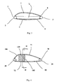
- FIG. 4 partially and schematically represents an exemplary embodiment of a light aircraft according to the invention, and more particularly a cross section of a wing.
- FIG. 5 represents an enlarged partial longitudinal section along the line II-II of FIG. 4.
- Figure 6 shows an enlarged detail of Figure 5.
- Such aircraft are known to those skilled in the art and will not be more particularly described here.
- a lightweight motorized aircraft commercially available under the name "Skyranger”, manufactured and distributed by the Applicant, rigid tubular frame type and flexible envelope, on which the characterizing part of the present invention can be applied.
- a non-motorized glider-type aircraft may also be suitable. The description which follows therefore relates to the only structure of the wing of the aircraft according to the invention, the complementary part of the latter (fuselage) to form the complete aircraft being of the domain of the prior art known of the skilled person at the date of filing of the present application.
- FIGS. 1, 2 and 3 described above show an example of a light aircraft wing structure according to the state of the art known at the filing date of the present application, on which the characterizing part of FIG. the present invention.
- the rigid frame 1 known according to FIG. 1 is a tubular type frame with triangulation assembly 5 for stiffening the wing bearing structure.
- the rigid framework 1 is covered in known manner with a flexible envelope 6 which defines in combination with it the wing profile, by means of rods 7 of profile or predetermined shape along their length, in the example of the tubes 7 inserted in longitudinal sleeves 8 formed on the upper and lower surfaces of the flexible envelope 6, as shown in Figure 2.
- the tubes 7 are placed substantially in a plane parallel to the axis of the aircraft.
- a tube 7 is enclosed in its respective sheath for example by means of an opening that can be closed after inserting the tube.
- the tubes 7 substantially provide a "connection" between the leading edge beam 2 and the trailing edge beam 3 in order to ensure a substantially rigid profile. continuous between the leading edge and the trailing edge.
- the aircraft furthermore comprises a plurality of rigid spacers 120 disposed respectively between an extrados rod 71 and a lower pressure rod 72, the lower pressure rod 72 and the extrados rod 71 between which a spacer 120 is disposed being substantially aligned in a vertical plane 104, corresponding to the plane of the sheet in the example of Figure 4, to maintain a predetermined fixed spacing between the rod of 72 and the extrados stem 71.
- the spacer 120 can deviate from the alignment in the vertical plane 104 to be engaged on a lower pressure shank and an extrados stem that would not be exactly aligned in said vertical plane. However, it is in the vertical plane that the spacer 120 will have an optimized resistance to aerodynamic forces.
- FIGS. 4, 5 and 6 the elements fulfilling the same function as those of FIGS. 1 to 3 of the prior art have been assigned the same numerical references multiplied by the number 10.
- the rigid rods 7 of the wing profile Figures 1 to 3 have further been decomposed into upper and lower shanks 71 and 72 in Figures 4 to 6.
- the flexible envelope 60 comprises a plurality of housings 80 substantially contained in parallel vertical planes, in which are housed said plurality of rigid upper-axis rods 71 and said plurality of rigid lower-wing rods 72 of a wing , and the plurality of spacers 120 is associated with the rigid extrados 71 and lower pressure rods 72 via the flexible envelope 60.
- the housings 80 are in a known manner, respectively constituted by flexible sleeves integral with the flexible envelope and formed for example by association of a local flexible sheet 101 with a sheet 102 constituting the envelope 60, to define a pocket-shaped housing, of a specific, elongated shape, able to guide and maintain in the desired position a rigid rod 71 or 72 of wing profile that is slid into the flexible sheath.
- a spacer 120 of the plurality of rigid spacers occupies a partial space between the leading edge beam and the trailing edge beam.
- the spacer 120 is advantageously limited in length to a zone 105 corresponding to the thickest part of the wing profile 106.
- the length of the spacer more specifically the range on a lower pressure rod or extrados rod may advantageously be between a point support and 30% of the length of the wing profile, preferably between 5% and 15% of this length in order to lighten the device while ensuring a resistance of the thickness of the profile in the area most stressed by the aerodynamic forces.
- a spacer 120 of the plurality of spacers is associated with the flexible envelope 60 or the rigid extrados 71 and intrados 72 rigid rods by a self-locking type connection, whose self-locking characteristic is provided when the aircraft is in flight.
- Such an effect is preferably obtained by ensuring the support of the spacer on a squeegee or extrados stem via the flexible envelope 60 which surrounds each rod, at least in an area in which the profile upper and lower shanks are convergent towards the trailing edge, preferably in a curved zone of the length of the shank having a portion converging towards the extrados and a portion converging towards the underside, preferably the most curve, or towards the leading edge of the wing, as shown in FIG. 4.
- the plurality of spacers 120 is removably associated with the flexible envelope 60 or with said rigid upper and lower pressure rods.
- a spacer 120 of the plurality of spacers is removably associated with the flexible casing 60 or the rigid upper and lower suction rods 71, for example by means of a quick-release linkage 121 of the "Velcro" type or analogous, as shown in Figure 6.
- the casing 60 is provided with a first attachment portion of the velcro link 121, disposed along the sheath 80 on the inner surface 101 of the casing 60, in correspondence with the intrados or extrados rod disposed in the sheath, so that a bearing on the first hanging part of the "Velcro” connection is transmitted to the rod inside the sheath.
- the second part of the "Velcro” connection is associated with the spacer 120, more particularly with the part of the spacer intended to bear on the rod 71 or 72 via the envelope 60.
- the two ends of a spacer 120 intended to bear respectively on the intrados 72 and extrados 71 stem via the envelope 60 are thus respectively provided with a portion of the "Velcro" connection, the other complementary part of this link being associated with the flexible envelope , respectively in intrados and extrados facing the rods.
- the hook-and-loop fastener of the "Velcro” type provides a sufficiently strong connection, especially since the spacer 120 will be disposed in an area of the profile ensuring self-locking of the connection as explained above.
- a spacer 120 of the plurality of rigid spacers has interfaces with the upper and lower suction rods 71 71, adopting the shape of a groove 122, adopting for example a V-shaped section, U, or arc of circle within which is disposed the extrados rod 71 or the intrados shank 72, as shown in Figure 6 which illustrates the enlarged detail of the connection between the spacer 120 and the intrados or the extrados.
- the cross section of the groove 122 will preferably adopt a shape complementary to the section of the intrados shank 72 or of the extrados 71, especially in the case of a Velcro-type adhesive tape bonding, in order to ensure a pressure per contact on the largest possible area of adhesive tape.
- the groove 122 may advantageously adopt a section in the form of a circular arc, as shown in FIG.
- the spacer 120 may take the form of a volume of light material, for example plastic, composite, or the shape of a bar structure, tubular preference, defining two or more points of support at the end of the bars on the lower and upper pressure rods respectively.
- a simple bar can constitute a spacer, the supports in extrados and intrados being provided by the ends of this bar provided for the circumstance preferably a bearing surface to reduce the pressure on the upper and lower pressure rods or on the flexible envelope, this taking into account the pressure necessary to ensure the connection between the spacer 120 and the upper and lower pressure rods or ducts containing them, which should preferably be a complete connection.
- the spacer 120 may alternatively consist of a plate of light material, hollow or not, the grooves 122 being formed in the thickness of the plate on an upper edge and a lower edge of the plate.
- connection between the spacer 120 and a lower or upper pressure rod can be achieved for example by means of a clamping jaw or an elastic clip; a self-locking type connection as described above can be in this case further applied.
Landscapes
- Engineering & Computer Science (AREA)
- Mechanical Engineering (AREA)
- Aviation & Aerospace Engineering (AREA)
- Tires In General (AREA)
- Tents Or Canopies (AREA)
- Walking Sticks, Umbrellas, And Fans (AREA)
- Toys (AREA)
- Transition And Organic Metals Composition Catalysts For Addition Polymerization (AREA)
- Shaping Of Tube Ends By Bending Or Straightening (AREA)
- Connection Of Plates (AREA)
Applications Claiming Priority (1)
| Application Number | Priority Date | Filing Date | Title |
|---|---|---|---|
| FR0608296A FR2906219B1 (fr) | 2006-09-22 | 2006-09-22 | Aeronef leger, comportant des ailes perfectionnees |
Publications (2)
| Publication Number | Publication Date |
|---|---|
| EP1902946A1 true EP1902946A1 (de) | 2008-03-26 |
| EP1902946B1 EP1902946B1 (de) | 2009-04-29 |
Family
ID=37908135
Family Applications (1)
| Application Number | Title | Priority Date | Filing Date |
|---|---|---|---|
| EP07352005A Not-in-force EP1902946B1 (de) | 2006-09-22 | 2007-09-21 | Leichtes Luftschiff, das mit perfektionierten Flügeln ausgestattet ist |
Country Status (4)
| Country | Link |
|---|---|
| EP (1) | EP1902946B1 (de) |
| AT (1) | ATE430090T1 (de) |
| DE (1) | DE602007001009D1 (de) |
| FR (1) | FR2906219B1 (de) |
Citations (4)
| Publication number | Priority date | Publication date | Assignee | Title |
|---|---|---|---|---|
| GB190927988A (en) * | 1909-12-01 | 1910-10-20 | John Wilfrid Seddon | Improvements in or relating to the Manufacture of Wings or Planes as used in Aeroplanes. |
| FR493993A (fr) * | 1917-12-19 | 1919-08-27 | John William Rapp | Perfectionnements dans la construction des nervures pour ailes et autres surfaces d'aéroplanes |
| CH139630A (de) * | 1929-04-27 | 1930-04-30 | Birlauf Bernhard | Tragfläche an Flugzeugen. |
| US6260795B1 (en) * | 1998-06-02 | 2001-07-17 | Kenneth Earl Gay | Oya computerized glider |
-
2006
- 2006-09-22 FR FR0608296A patent/FR2906219B1/fr not_active Expired - Fee Related
-
2007
- 2007-09-21 DE DE602007001009T patent/DE602007001009D1/de active Active
- 2007-09-21 EP EP07352005A patent/EP1902946B1/de not_active Not-in-force
- 2007-09-21 AT AT07352005T patent/ATE430090T1/de not_active IP Right Cessation
Patent Citations (4)
| Publication number | Priority date | Publication date | Assignee | Title |
|---|---|---|---|---|
| GB190927988A (en) * | 1909-12-01 | 1910-10-20 | John Wilfrid Seddon | Improvements in or relating to the Manufacture of Wings or Planes as used in Aeroplanes. |
| FR493993A (fr) * | 1917-12-19 | 1919-08-27 | John William Rapp | Perfectionnements dans la construction des nervures pour ailes et autres surfaces d'aéroplanes |
| CH139630A (de) * | 1929-04-27 | 1930-04-30 | Birlauf Bernhard | Tragfläche an Flugzeugen. |
| US6260795B1 (en) * | 1998-06-02 | 2001-07-17 | Kenneth Earl Gay | Oya computerized glider |
Also Published As
| Publication number | Publication date |
|---|---|
| ATE430090T1 (de) | 2009-05-15 |
| DE602007001009D1 (de) | 2009-06-10 |
| FR2906219B1 (fr) | 2009-07-03 |
| FR2906219A1 (fr) | 2008-03-28 |
| EP1902946B1 (de) | 2009-04-29 |
Similar Documents
| Publication | Publication Date | Title |
|---|---|---|
| CA2585869C (fr) | Cadre de structure de fuselage d'aeronef | |
| EP1614622B1 (de) | Flugzeugcockpitboden | |
| EP1614625A1 (de) | Flugzeugdeck | |
| EP1957361B1 (de) | Flugzeug-unterverkleidungs-trennwand und flugzeug mit einer unterverkleidung | |
| EP3157808B1 (de) | Flügel für den antrieb eines fahrzeuges | |
| FR2941915A1 (fr) | Aeronef presentant deux paires d'ailes | |
| FR2872781A1 (fr) | Plancher pour aeronef | |
| CA2702908A1 (fr) | Structure d'avion comportant des jonctions d'arrets de raidisseurs | |
| WO2011033218A1 (fr) | Bagage souple a roulettes orientables | |
| FR2891526A1 (fr) | Mat d'accrochage de turboreacteur pour aeronef | |
| FR3059298A1 (fr) | Ensemble pour aeronef comprenant un moteur de type " open rotor puller " et des moyens d'accrochage de celui-ci a la structure rigide d'un mat d'accrochage | |
| FR2924681A1 (fr) | Element aerodynamique allonge deformable en torsion | |
| WO2013160457A1 (fr) | Dispositif de revêtement d'une structure de bâtiment et structure revêtue par un tel dispositif | |
| EP1902946B1 (de) | Leichtes Luftschiff, das mit perfektionierten Flügeln ausgestattet ist | |
| EP3524515B1 (de) | Flugzeuganordnung mit einer beweglichen tragfläche, die von einer betätigungswelle getragen wird, die durch einen mit einer dichtung mit verbesserter dichtungseffizienz versehenen schlitz verläuft | |
| EP3945518B1 (de) | Akustikmaterial aus streifen mit integriertem flansch und innenwand eines lufteinlasses eines luftfahrzeugs aus diesem material | |
| FR3117998A1 (fr) | Portion d’aéronef à trainée d’onde réduite | |
| EP1292488B1 (de) | Radträgervorrichtung und vibrationsdämpfer für eine solche vorrichtung | |
| BE1016117A3 (fr) | Volet mobile de bord d'attaque d'une aile principale de la voilure d'un aeronef. | |
| FR2992289A1 (fr) | Train d'atterrissage d'un aeronef et aeronef | |
| FR3085645A1 (fr) | Ensemble formant une gaine d’habillage de colonne de direction et vehicule presentant une telle gaine | |
| FR3081831A1 (fr) | Paroi aerodynamique d’aeronef comportant au moins un generateur de tourbillons et aeronef comprenant ladite paroi aerodynamique | |
| FR2984273A1 (fr) | Support de plancher d'aeronef | |
| FR2872779A1 (fr) | Plancher de cockpit pour aeronef | |
| WO1981000666A1 (fr) | Procede de fabrication de meubles a assemblage par profiles tubulaires meubles selon le procede |
Legal Events
| Date | Code | Title | Description |
|---|---|---|---|
| PUAI | Public reference made under article 153(3) epc to a published international application that has entered the european phase |
Free format text: ORIGINAL CODE: 0009012 |
|
| AK | Designated contracting states |
Kind code of ref document: A1 Designated state(s): AT BE BG CH CY CZ DE DK EE ES FI FR GB GR HU IE IS IT LI LT LU LV MC MT NL PL PT RO SE SI SK TR |
|
| AX | Request for extension of the european patent |
Extension state: AL BA HR MK YU |
|
| 17P | Request for examination filed |
Effective date: 20080915 |
|
| GRAP | Despatch of communication of intention to grant a patent |
Free format text: ORIGINAL CODE: EPIDOSNIGR1 |
|
| AKX | Designation fees paid |
Designated state(s): AT BE BG CH CY CZ DE DK EE ES FI FR GB GR HU IE IS IT LI LT LU LV MC MT NL PL PT RO SE SI SK TR |
|
| GRAS | Grant fee paid |
Free format text: ORIGINAL CODE: EPIDOSNIGR3 |
|
| GRAA | (expected) grant |
Free format text: ORIGINAL CODE: 0009210 |
|
| AK | Designated contracting states |
Kind code of ref document: B1 Designated state(s): AT BE BG CH CY CZ DE DK EE ES FI FR GB GR HU IE IS IT LI LT LU LV MC MT NL PL PT RO SE SI SK TR |
|
| REG | Reference to a national code |
Ref country code: GB Ref legal event code: FG4D Free format text: NOT ENGLISH |
|
| REG | Reference to a national code |
Ref country code: CH Ref legal event code: EP |
|
| REF | Corresponds to: |
Ref document number: 602007001009 Country of ref document: DE Date of ref document: 20090610 Kind code of ref document: P |
|
| REG | Reference to a national code |
Ref country code: IE Ref legal event code: FG4D |
|
| NLV1 | Nl: lapsed or annulled due to failure to fulfill the requirements of art. 29p and 29m of the patents act | ||
| PG25 | Lapsed in a contracting state [announced via postgrant information from national office to epo] |
Ref country code: AT Free format text: LAPSE BECAUSE OF FAILURE TO SUBMIT A TRANSLATION OF THE DESCRIPTION OR TO PAY THE FEE WITHIN THE PRESCRIBED TIME-LIMIT Effective date: 20090429 Ref country code: FI Free format text: LAPSE BECAUSE OF FAILURE TO SUBMIT A TRANSLATION OF THE DESCRIPTION OR TO PAY THE FEE WITHIN THE PRESCRIBED TIME-LIMIT Effective date: 20090429 Ref country code: PT Free format text: LAPSE BECAUSE OF FAILURE TO SUBMIT A TRANSLATION OF THE DESCRIPTION OR TO PAY THE FEE WITHIN THE PRESCRIBED TIME-LIMIT Effective date: 20090829 Ref country code: LT Free format text: LAPSE BECAUSE OF FAILURE TO SUBMIT A TRANSLATION OF THE DESCRIPTION OR TO PAY THE FEE WITHIN THE PRESCRIBED TIME-LIMIT Effective date: 20090429 Ref country code: ES Free format text: LAPSE BECAUSE OF FAILURE TO SUBMIT A TRANSLATION OF THE DESCRIPTION OR TO PAY THE FEE WITHIN THE PRESCRIBED TIME-LIMIT Effective date: 20090809 |
|
| PG25 | Lapsed in a contracting state [announced via postgrant information from national office to epo] |
Ref country code: SE Free format text: LAPSE BECAUSE OF FAILURE TO SUBMIT A TRANSLATION OF THE DESCRIPTION OR TO PAY THE FEE WITHIN THE PRESCRIBED TIME-LIMIT Effective date: 20090729 Ref country code: PL Free format text: LAPSE BECAUSE OF FAILURE TO SUBMIT A TRANSLATION OF THE DESCRIPTION OR TO PAY THE FEE WITHIN THE PRESCRIBED TIME-LIMIT Effective date: 20090429 Ref country code: NL Free format text: LAPSE BECAUSE OF FAILURE TO SUBMIT A TRANSLATION OF THE DESCRIPTION OR TO PAY THE FEE WITHIN THE PRESCRIBED TIME-LIMIT Effective date: 20090429 Ref country code: LV Free format text: LAPSE BECAUSE OF FAILURE TO SUBMIT A TRANSLATION OF THE DESCRIPTION OR TO PAY THE FEE WITHIN THE PRESCRIBED TIME-LIMIT Effective date: 20090429 Ref country code: IS Free format text: LAPSE BECAUSE OF FAILURE TO SUBMIT A TRANSLATION OF THE DESCRIPTION OR TO PAY THE FEE WITHIN THE PRESCRIBED TIME-LIMIT Effective date: 20090829 Ref country code: SI Free format text: LAPSE BECAUSE OF FAILURE TO SUBMIT A TRANSLATION OF THE DESCRIPTION OR TO PAY THE FEE WITHIN THE PRESCRIBED TIME-LIMIT Effective date: 20090429 |
|
| REG | Reference to a national code |
Ref country code: IE Ref legal event code: FD4D |
|
| PG25 | Lapsed in a contracting state [announced via postgrant information from national office to epo] |
Ref country code: RO Free format text: LAPSE BECAUSE OF FAILURE TO SUBMIT A TRANSLATION OF THE DESCRIPTION OR TO PAY THE FEE WITHIN THE PRESCRIBED TIME-LIMIT Effective date: 20090429 Ref country code: EE Free format text: LAPSE BECAUSE OF FAILURE TO SUBMIT A TRANSLATION OF THE DESCRIPTION OR TO PAY THE FEE WITHIN THE PRESCRIBED TIME-LIMIT Effective date: 20090429 Ref country code: IE Free format text: LAPSE BECAUSE OF FAILURE TO SUBMIT A TRANSLATION OF THE DESCRIPTION OR TO PAY THE FEE WITHIN THE PRESCRIBED TIME-LIMIT Effective date: 20090429 Ref country code: DK Free format text: LAPSE BECAUSE OF FAILURE TO SUBMIT A TRANSLATION OF THE DESCRIPTION OR TO PAY THE FEE WITHIN THE PRESCRIBED TIME-LIMIT Effective date: 20090429 Ref country code: CZ Free format text: LAPSE BECAUSE OF FAILURE TO SUBMIT A TRANSLATION OF THE DESCRIPTION OR TO PAY THE FEE WITHIN THE PRESCRIBED TIME-LIMIT Effective date: 20090429 |
|
| PG25 | Lapsed in a contracting state [announced via postgrant information from national office to epo] |
Ref country code: SK Free format text: LAPSE BECAUSE OF FAILURE TO SUBMIT A TRANSLATION OF THE DESCRIPTION OR TO PAY THE FEE WITHIN THE PRESCRIBED TIME-LIMIT Effective date: 20090429 |
|
| PLBE | No opposition filed within time limit |
Free format text: ORIGINAL CODE: 0009261 |
|
| STAA | Information on the status of an ep patent application or granted ep patent |
Free format text: STATUS: NO OPPOSITION FILED WITHIN TIME LIMIT |
|
| BERE | Be: lapsed |
Owner name: PREVOT, PHILIPPE Effective date: 20090930 |
|
| PG25 | Lapsed in a contracting state [announced via postgrant information from national office to epo] |
Ref country code: BG Free format text: LAPSE BECAUSE OF FAILURE TO SUBMIT A TRANSLATION OF THE DESCRIPTION OR TO PAY THE FEE WITHIN THE PRESCRIBED TIME-LIMIT Effective date: 20090729 |
|
| 26N | No opposition filed |
Effective date: 20100201 |
|
| PG25 | Lapsed in a contracting state [announced via postgrant information from national office to epo] |
Ref country code: MC Free format text: LAPSE BECAUSE OF NON-PAYMENT OF DUE FEES Effective date: 20090930 |
|
| REG | Reference to a national code |
Ref country code: FR Ref legal event code: ST Effective date: 20100531 |
|
| PG25 | Lapsed in a contracting state [announced via postgrant information from national office to epo] |
Ref country code: FR Free format text: LAPSE BECAUSE OF NON-PAYMENT OF DUE FEES Effective date: 20090930 |
|
| REG | Reference to a national code |
Ref country code: FR Ref legal event code: RN |
|
| PG25 | Lapsed in a contracting state [announced via postgrant information from national office to epo] |
Ref country code: BE Free format text: LAPSE BECAUSE OF NON-PAYMENT OF DUE FEES Effective date: 20090930 |
|
| PG25 | Lapsed in a contracting state [announced via postgrant information from national office to epo] |
Ref country code: GR Free format text: LAPSE BECAUSE OF FAILURE TO SUBMIT A TRANSLATION OF THE DESCRIPTION OR TO PAY THE FEE WITHIN THE PRESCRIBED TIME-LIMIT Effective date: 20090730 |
|
| REG | Reference to a national code |
Ref country code: FR Ref legal event code: D3 |
|
| PGRI | Patent reinstated in contracting state [announced from national office to epo] |
Ref country code: FR Effective date: 20101109 |
|
| PG25 | Lapsed in a contracting state [announced via postgrant information from national office to epo] |
Ref country code: IT Free format text: LAPSE BECAUSE OF FAILURE TO SUBMIT A TRANSLATION OF THE DESCRIPTION OR TO PAY THE FEE WITHIN THE PRESCRIBED TIME-LIMIT Effective date: 20090429 |
|
| PG25 | Lapsed in a contracting state [announced via postgrant information from national office to epo] |
Ref country code: MT Free format text: LAPSE BECAUSE OF FAILURE TO SUBMIT A TRANSLATION OF THE DESCRIPTION OR TO PAY THE FEE WITHIN THE PRESCRIBED TIME-LIMIT Effective date: 20090429 Ref country code: LU Free format text: LAPSE BECAUSE OF NON-PAYMENT OF DUE FEES Effective date: 20090921 |
|
| PG25 | Lapsed in a contracting state [announced via postgrant information from national office to epo] |
Ref country code: HU Free format text: LAPSE BECAUSE OF FAILURE TO SUBMIT A TRANSLATION OF THE DESCRIPTION OR TO PAY THE FEE WITHIN THE PRESCRIBED TIME-LIMIT Effective date: 20091030 |
|
| PG25 | Lapsed in a contracting state [announced via postgrant information from national office to epo] |
Ref country code: TR Free format text: LAPSE BECAUSE OF FAILURE TO SUBMIT A TRANSLATION OF THE DESCRIPTION OR TO PAY THE FEE WITHIN THE PRESCRIBED TIME-LIMIT Effective date: 20090429 |
|
| PG25 | Lapsed in a contracting state [announced via postgrant information from national office to epo] |
Ref country code: CY Free format text: LAPSE BECAUSE OF FAILURE TO SUBMIT A TRANSLATION OF THE DESCRIPTION OR TO PAY THE FEE WITHIN THE PRESCRIBED TIME-LIMIT Effective date: 20090429 |
|
| REG | Reference to a national code |
Ref country code: CH Ref legal event code: PL |
|
| PG25 | Lapsed in a contracting state [announced via postgrant information from national office to epo] |
Ref country code: LI Free format text: LAPSE BECAUSE OF NON-PAYMENT OF DUE FEES Effective date: 20110930 Ref country code: CH Free format text: LAPSE BECAUSE OF NON-PAYMENT OF DUE FEES Effective date: 20110930 |
|
| REG | Reference to a national code |
Ref country code: FR Ref legal event code: PLFP Year of fee payment: 10 |
|
| PGFP | Annual fee paid to national office [announced via postgrant information from national office to epo] |
Ref country code: GB Payment date: 20160916 Year of fee payment: 10 Ref country code: DE Payment date: 20160914 Year of fee payment: 10 |
|
| PGFP | Annual fee paid to national office [announced via postgrant information from national office to epo] |
Ref country code: FR Payment date: 20160829 Year of fee payment: 10 |
|
| REG | Reference to a national code |
Ref country code: DE Ref legal event code: R119 Ref document number: 602007001009 Country of ref document: DE |
|
| GBPC | Gb: european patent ceased through non-payment of renewal fee |
Effective date: 20170921 |
|
| REG | Reference to a national code |
Ref country code: FR Ref legal event code: ST Effective date: 20180531 |
|
| PG25 | Lapsed in a contracting state [announced via postgrant information from national office to epo] |
Ref country code: GB Free format text: LAPSE BECAUSE OF NON-PAYMENT OF DUE FEES Effective date: 20170921 Ref country code: DE Free format text: LAPSE BECAUSE OF NON-PAYMENT OF DUE FEES Effective date: 20180404 |
|
| PG25 | Lapsed in a contracting state [announced via postgrant information from national office to epo] |
Ref country code: FR Free format text: LAPSE BECAUSE OF NON-PAYMENT OF DUE FEES Effective date: 20171002 |