EP1902956A1 - Dispositif de dosage pour un matériau de dosage en forme de pulvérisateur ou de pâte - Google Patents
Dispositif de dosage pour un matériau de dosage en forme de pulvérisateur ou de pâte Download PDFInfo
- Publication number
- EP1902956A1 EP1902956A1 EP06121165A EP06121165A EP1902956A1 EP 1902956 A1 EP1902956 A1 EP 1902956A1 EP 06121165 A EP06121165 A EP 06121165A EP 06121165 A EP06121165 A EP 06121165A EP 1902956 A1 EP1902956 A1 EP 1902956A1
- Authority
- EP
- European Patent Office
- Prior art keywords
- vessel
- dosing
- drive device
- counterpart
- removal
- Prior art date
- Legal status (The legal status is an assumption and is not a legal conclusion. Google has not performed a legal analysis and makes no representation as to the accuracy of the status listed.)
- Granted
Links
Images


Classifications
-
- B—PERFORMING OPERATIONS; TRANSPORTING
- B65—CONVEYING; PACKING; STORING; HANDLING THIN OR FILAMENTARY MATERIAL
- B65B—MACHINES, APPARATUS OR DEVICES FOR, OR METHODS OF, PACKAGING ARTICLES OR MATERIALS; UNPACKING
- B65B3/00—Packaging plastic material, semiliquids, liquids or mixed solids and liquids, in individual containers or receptacles, e.g. bags, sacks, boxes, cartons, cans, or jars
- B65B3/26—Methods or devices for controlling the quantity of the material fed or filled
- B65B3/30—Methods or devices for controlling the quantity of the material fed or filled by volumetric measurement
-
- G—PHYSICS
- G01—MEASURING; TESTING
- G01F—MEASURING VOLUME, VOLUME FLOW, MASS FLOW OR LIQUID LEVEL; METERING BY VOLUME
- G01F13/00—Apparatus for measuring by volume and delivering fluids or fluent solid materials, not provided for in the preceding groups
- G01F13/001—Apparatus for measuring by volume and delivering fluids or fluent solid materials, not provided for in the preceding groups for fluent solid material
Definitions
- the present invention relates to a metering device for powdered or pasty Dosiergut.
- Such metering devices find particular use when dosing small amounts, such as toxic substances, with high precision in small target vessels use. Frequently, such target vessels are placed on a balance in order to weigh the amount of substance discharged from the metering device, so that it can subsequently be further processed as intended.
- the substance to be dosed is located, for example, in a removal vessel which has a dosing head. It is desirable to discharge the substance to be metered through a small opening of the metering device, so that it can also be filled in a targeted manner into a vessel with a small opening cross-section.
- Dosing devices for dry and / or powdery bulk material, such as dye powder are known and in use. So will in the US 5 145 009 A a device for dosing described, which consists of a sampling vessel with a closable outlet on its underside. As a closure element serves a conical, tapering upwards to open an outlet opening vertically downwardly adjustable valve body which rotates in its open position and has means for conveying the goods in the direction of the outlet opening. Furthermore, the removal vessel is penetrated by a drive shaft which projects beyond the top of the removal vessel and is coupled to a drive. The removal vessel is connected by a mounting flange on its underside with the metering device.
- a dosage in the microgram range requires very rigid connections between the drive and the withdrawal vessel used, since in the final phase of the metering process the residual metered amount over smallest changes of the rotation angle and the linear stroke of the valve body is metered.
- the described device Due to the requirements for the attachment of the removal vessel in the metering device, the described device has the disadvantage that the removal vessel and the interfaces to the removal vessel must be matched very closely to each other, so that when inserted into the metering removal vessel, the drive shaft can be coupled to the drive. The resulting tight shape and position tolerances lead to very expensive workpieces. Furthermore, the insertion of the extraction vessel requires, depending on the design of the mounting flange through the necessary alignment work long setup times. This metering device is therefore very tied to the infrastructure of the site.
- the present invention therefore has for its object to provide a metering device that allows easy and quick replaceability of the sampling vessel.
- a metering device for powdered or pasty Dosiergut has a drive device and an insertable into the drive device removal vessel, wherein in the operating position on the underside of the removal vessel a dosing is arranged with a rotatably driven closure body, which is movably mounted with a removal vessel Lock shaft is connected.
- the closure shaft has a coupling part in the region of a passage point at the top of the extraction vessel. The coupling part can be coupled or decoupled from a drive shaft of the drive device.
- the removal vessel has a first mold element which positively corresponds to a first counterpart formed on the drive device and which serves to precisely position the coupling part with respect to the drive shaft in a plane orthogonal to the axis of rotation of the drive shaft. Furthermore, the removal vessel has a second form element, which corresponds positively to a second counterpart formed on the drive device and in the operating position of the precise one spatial positioning of the dosing with respect to a, arranged below the dosing head target vessel serves.
- the first interface between the extraction vessel and the drive device relates to the coupling of the drive shaft with the closure shaft
- the second interface relates to the positioning of the metering opening relative to the filling opening of a target vessel.
- first mold element are spatially positioned only in the plane and the second mold element, a statically determined mechanical connection between the sampling vessel and the drive device is created.
- first and the second mold element no tight length tolerances necessary.
- thermally induced changes in the withdrawal vessel height do not lead to tension in the system.
- Small differences in length of different sampling vessels can be compensated by a height-adjustable drive or by a length compensation in the coupling part.
- the sampling vessel may have any shape. Due to the spatially close arrangement of the first element element in relation to the coupling part, as well as the first counterpart in relation to the drive shaft, this interface between the drive device and the sampling vessel can be defined without much effort.
- the second mold element which is arranged spatially close to this with respect to the dosing head and for the filling opening of the target vessel, which can be accurately positioned relative to the second counterpart.
- aids such as markings on the load receptor of a balance or a load receiver adapted to the target vessel in the embodiment are conceivable.
- the distance of the first counterpart is preferably second counterpart adjustable and thereby adaptable to the distance of the first element element to the second mold element of a corresponding extraction vessel.
- the use of extraction vessels of different lengths offers various advantages.
- extraction vessels of the same cross-section with different volumes can be produced.
- the use of identical cross-sections means that the removal vessels differ only in their length and thus the peripherals and interfaces to the drive device need not be changed.
- small quantities of dosing material can be stored in large vessels. Apart from the greater space required for logistics, which entails the use of large vessels, large dead volumes within the sampling vessel are undesirable.
- the medium present in the dead volume can lead to a more rapid aging of the substance stored in the withdrawal vessel. Since the extraction vessels are also intended for very expensive substances, it is advantageous if it can be selected from a number of sampling vessels with different volumes. This results in small amounts to be dosed a smaller dead volume and less adhesion surface in the removal vessel to which a part of the dosing can adhere and thereby the amount actually dosable is reduced.
- the distance between the second counterpart and a filling opening of the target vessel, or in the case of the withdrawal vessel inserted into the drive device is adjustable between the dosing head and a filling opening of the target vessel. This allows target vessels with different vessel heights to be placed under the dosing head.
- the axis of rotation of the closure shaft, the axis of rotation of the drive shaft and optionally the center of area of the filling opening of the target vessel are in line when the removal vessel is inserted into the drive device in the ready state.
- the drive device is electrically and / or mechanically connected to a force-measuring device, in particular a balance.
- a force-measuring device in particular a balance.
- This can detect appropriate control and regulating variables during dosing for controlling and regulating the metering process.
- the tax and Controlled variables in particular the change in the weight values as a function of time, can be processed in a control and regulation unit and their output values act in a suitable manner on the drive device.
- the balance is preferably positioned so that the centroid of the load receptor, or the weighing pan, is arranged below the dosing to avoid any corner load error.
- the target vessel rests during the dosing process on the load receiver, whereby a continuous weight value detection and thus the control and regulation of the dosing process is made possible.
- the removal vessel therefore has a tubular central part, with the lower end of the dosing head, and with the upper end of a lid are releasably and / or monolithically connected.
- the passage point as well as the first mold element on the lid and the second mold element are formed on the dosing.
- the tubular central part may have any cross-section orthogonal to the axis of rotation of the closure shaft. Furthermore, the tubular central part does not necessarily have to be rod-shaped, it can have any desired cross-sectional changes along its length. For removal vessels with a cross-section which remains the same over their length, the volume of the removal vessel can be determined by the length of the tubular central part.
- the first mold element Since the first mold element has to position the removal vessel in relation to the drive device only in the plane orthogonal to the axis of rotation of the drive shaft, the first mold element is preferably cylindrical or barrel-shaped. However, it can also have any shape, provided that at least the contact points with the first counterpart are arranged on the mold element on a circle in the plane orthogonal to the axis of rotation, wherein the center of this circle lies on the axis of rotation of the shutter shaft. Ideally, the shaped element is tubular formed and encloses radially at the same time the passage point of the closure shaft and / or the coupling part, with which the closure shaft is connected.
- the sampling vessel can be used horizontally in relation to the load direction in the drive device
- the first counterpart preferably has a fork part whose slot width corresponds to the width of the first mold element and in the slot bottom a stop for the first mold element is formed.
- the removal vessel used could fall out of the drive device again by such a configuration in that the first mold element is shaken out of the first counterpart as a result of vibrations. Therefore, preferably at the first counterpart at least one acting on the first mold element or on the withdrawal vessel retaining pawl is arranged, which serves to secure the used removal vessel against accidental falling out.
- a second mold element which interacts in a form-fitting manner with the second counterpart when the sampling vessel is inserted.
- a spatially stable positioning is preferably achieved in that at least one ball zone is formed on the second mold element, the ball center is located on the axis of rotation of the closure shaft.
- the second counterpart has a breakthrough or cut at least partially tapered in the load direction. In this at least three points of contact are formed, which are arranged in a plane orthogonal to the drive axis and at the same distance from the drive axis, touching the ball zone with the removal vessel inserted, whereby the removal vessel is spatially positioned with respect to the drive device or the target vessel.
- angles enclosed by the connecting lines extending from the center of the sphere to two respective contact points are preferably less than 180 °, since otherwise stable positioning is no longer guaranteed.
- a fork-shaped ausgestaltetes counterpart which formed between the forks incision at least in the cutting base has a tapered in the load direction cone edge.
- the removal vessel or at least the first mold element and the second mold element with respect to the axis of rotation of the closure shaft is configured rotationally symmetrical.
- the removal vessel is position-independent with respect to its axis of rotation when inserted into the drive device.
- the removal vessel can be freely rotated about the axis of rotation after insertion into the drive device. This has the advantage that with positive couplings, the removal vessel with respect to the axis of rotation of the closure shaft, for example, by hand can be rotated in the correct position until the coupling parts can be joined together.
- an anti-twist device should also be arranged which serves to absorb torques which act on the removal vessel from the drive device or from the environment.
- a rotation can serve a simple cam, which engages in a groove. If this cam is connected via a spring element to the drive device, for example, a rotationally symmetrical ausgestaltetes extraction vessel can first be inserted into the drive device and then rotated about the axis of rotation of the shutter shaft until the cam engages in the groove formed on the removal vessel.
- the groove can also be formed on the drive device and the cam on the removal vessel.
- the rotation can also serve the overload protection of the drive, provided that it has a spring element.
- the maximum torque can be adjusted.
- the removal vessels preferably have an identification marking or an identification transmitter, for example a barcode, matrix code or an RFID tag.
- the identification reading device may be disposed at a suitable position in the driving device.
- the identification marking or the identification transmitter should be aligned relative to the identification reading device.
- a positioning can be done via the rotation, if this has at least one latching position. Due to this positioning, the reading point is precisely defined.
- the stored or printed data may include, for example, the length of the corresponding sampling vessel. These could be retrieved by the drive device and serve the automatic adjustment of the distance between the first counterpart and the second counterpart.
- the drive device may have a locking device which serves at least during the operating phases of securing the removal vessel used in the dosing device against axial displacements relative to the axis of rotation of the closure shaft.
- this can be supplemented with a charging device for removal vessels.
- a charging device for removal vessels In order to enable automated processes, at least the removal vessels must have suitable means by which the moving elements of the charging device, for example a robot arm, can engage.
- the removal vessel at least one, in a plane orthogonal to the axis of rotation of the closure shaft at least partially encircling collar on whose edge region is formed at least one in the load direction facing first projection.
- the at least one collar and the at least one first projection are formed concentrically to the closure shaft.
- the removal vessel is position-independent with respect to the axis of rotation of the closure shaft and thus considerably simplifies the automated processes.
- the charging device has at least one in its configuration with the collar and the at least one first projection positively corresponding receptacle.
- At least one fork-shaped support and at least one recess and / or a second projection are formed on the receptacle.
- the at least one fork-shaped support is at least partially used as a support when inserted into the receptacle sampling vessel the at least one fret. So that the removal vessel does not fall out of the fork-shaped receptacle during handling, the at least one recess partially or completely surrounds the at least one first projection or the second projection engages on the first projection.
- the sampling vessel By a linear displacement in the direction of the axis of rotation of the shutter shaft, the sampling vessel is suspended in the receptacle or lifted out of the receptacle.
- a receptacle configured allows a simple, automated insertion and removal of the sampling vessel from the drive device.
- the mixing of several substances usually requires the use of multiple sampling vessels. As long as they are not used in the drive device, they can be stored near the metering device in a multiple holder. This may be integrated in the feeder or separated from the feeder.
- the charging device is preferably connected to the drive device and at least one storage unit is arranged in the charging device and / or in the drive device.
- this storage unit the position of the withdrawal vessels stored in the multiple holder and their specific data such as the length of the removal vessel can be stored.
- Figure 4 shows the further embodiment of a second counterpart.
- FIG. 1 shows a metering device 100, which has a drive device 150 into which a removal vessel 110 can be inserted and removed again.
- the drive device 150 has an upper part 157 and a lower part 158 which are substantially linearly displaceable in the load direction of and against each other. This allows the use of extraction vessels 110, 110 'of different lengths.
- the removal vessel 110 or the drive device 150 must have suitable mechanical, optionally mechanical and electrical connecting elements which correspond to each other in a form-fitting manner.
- the removal vessel 110 has at least one first mold element 111, which is positioned in a plane orthogonal to the load direction by a first counterpart 151 formed on or connected to the upper part 157.
- the removal vessel 110 has at least one second mold element 121, which is spatially positioned relative to the drive device 150 by means of a second counterpart 181 formed on or connected to the lower part 158. This will be the sampling vessel 110 and its metering orifice with respect to a target vessel 200 exactly aligned.
- the removal vessel 110 in FIG. 1 has a cylindrical basic shape. In principle, however, other Ent.gefäss- forms with, for example, square, hexagonal or octagonal outer and inner cross section are possible.
- the removal vessel 110 inserted into the drive device 150 has in the operating position with its longitudinal axis in the load direction.
- a dosing head 122 is arranged at the lower end of the sampling vessel 110.
- a non-illustrated, rotationally driven closure body is integrated, which is connected to a closure shaft 110 movably mounted in the closure shaft 132.
- the body of the extraction vessel 110 is formed as a tubular central part 112 and is closed at the top by a cover 113.
- the cover 113 and the tubular middle part 112 may also be monolithically connected to each other.
- a passage point 130 in which the closure body opposite end of the closure shaft 132 is rotatably mounted and protrudes with this end of the removal vessel 110.
- This end of the closure shaft 132 has a coupling part 131, which is formed in this embodiment as a square piece and at least during the dosing process via a coupling sleeve 154 is connected to the drive 155 integrated in the drive device 155.
- the drive 155 or at least one drive shaft 156 connected to the drive should preferably be linearly displaceable in the load direction.
- the mechanical connection between the removal vessel 110 and the drive device 150 can be realized by the first mold element 111 is cylindrical, spherical or barrel-shaped and engages in a fork-shaped first counterpart 151.
- the slot width of the fork-shaped first counterpart 151 corresponds to the diameter of the first mold element 111.
- the slot end 152 acts as a stop for the mold element 111 and defines the distance of the used extraction vessel 110 to the upper part 157 and the lower part 158.
- the first mold element 111 not slips out of the first counterpart 151, presses a spring-loaded retaining pawl 153 as shown in Figure 2, the mold member 111 against the slot end 152.
- the retaining pawl 153 can be opened electromechanically or pneumatically. As shown in Figure 1 and Figure 2, by appropriate design of the latch nose, when removing the removal vessel 110, the retaining pawl 135 are pushed with considerable force by the mold member 111 aside.
- the spring-loaded retaining pawl 153 and / or the slot end 152 may additionally have electrical contacts which, when the removal vessel 110 is in contact with the first mold element 111 or the removal vessel 110, contact mating contacts and thereby establish an electrical connection between the removal vessel 110 and the drive device 150. Such electrical connection may also be used for identification purposes for earthing purposes of the sampling vessel, or as described below.
- the second counterpart 181 positions the extraction vessel 110 in cooperation with the second mold element 121 not only in the plane orthogonal to the load direction, but also uniquely supports the sampling vessel 110 in the load direction.
- the second mold element 121 has a spherical zone whose ball center lies on the longitudinal axis of the sampling vessel 110.
- the second counterpart 181 is likewise fork-shaped.
- the Schlitzcampus182 has a tapered in the load direction, conically shaped edge 183 or bevel. In this flank 183 is located at the withdrawal vessel 110 inserted the ball zone 121 and forms, except in the region of the slot, an annular support location.
- the bifurcation can be dispensed with in the case of the second counterpart 181.
- the second Counterpart 181 ' may also have a cylindrical or as shown in Figure 3 in section, have a tapering in the load direction opening.
- a third variant is shown schematically in FIG. 4 and shows the second counterpart 181 ", whose design by means of cams 184 forms a three-point support for the ball zone of the element 121.
- the drive device 150 further has a locking device 160 which, as shown in FIG. 2, acts on the cover 113 when the removal vessel 110 is inserted and secures the removal vessel 110 against displacement against the load direction.
- a locking device 160 which, as shown in FIG. 2, acts on the cover 113 when the removal vessel 110 is inserted and secures the removal vessel 110 against displacement against the load direction.
- These as already described in the retaining pawl 153, additionally have an electrical connection to the removal vessel and be actuated mechanically, electromechanically or pneumatically.
- the electrical connections can be used, for example, as a switch for actuating the retaining pawl 153 or its signals as an acknowledgment to the controller that really a sampling vessel is used.
- a recess 114 is formed on the lid.
- an anti-rotation lock 170 engages in this recess 114 in order to absorb and support the torque acting on the removal vessel 110 from the drive 155.
- the rotation lock 170 is formed in this embodiment as a simple spring tongue, so that when inserting the sampling vessel 110, the position of the recess 114 with respect to the anti-rotation 170 does not need to be considered.
- the drive is coupled to the closure shaft 132 via a drive shaft 156 and a torque acts on the closure shaft 132
- the removal vessel 110 is also rotated until the rotation lock 170 engages.
- the removal vessel 110 can also be rotated by hand into the correct position.
- anti-rotation 170 not only spring tongues, but also bolts, pins, clamps and the like can be used.
- the anti-twist device 170 can also have an electrical connection to the removal vessel 110, as already described for the retaining pawl 153.
- the illustrated anti-rotation lock 170 simultaneously acts as an overload protection for the drive, if the closure shaft 132 in the extraction vessel 110, 110 'blocked.
- the recess 114 formed at an arbitrary position of the removal vessel 110 and the rotation 170 on a be arranged according to matching position on the drive device 150.
- the advantage of the illustrated embodiment is that the removal vessel 110 with respect to the drive device 150 occupies a clearly defined position and is secured against further rotation. This supports the automatic identification of the removal vessel 110, since an identification mark 115 attached to the removal vessel 110, for example a barcode or matrix code, is precisely positioned relative to an identification reading device 175, a camera in FIG.
- the drive device 150 is mechanically connected via height-adjustable feet 159 and electrically via a connection, not shown, preferably with a force measuring device 190 on whose load receiver 191 the target vessel 200 is placed.
- the adjustability of the feet 159 allows the use of differently designed target vessels 200 with different vessel heights.
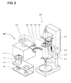
- FIG. 2 shows the metering device 100 from FIG. 1, a charging device 300 for removal vessels 110, 110 'and a multiple holder 400.
- the multiple holder 400 can be integrated into the charging device 300 or, as shown in FIG.
- a removal vessel 110 is inserted in the drive device 150 of the metering device 100.
- the drive shaft 156 is coupled to the shutter shaft 132.
- the drive shaft 156 must be displaceable in the load direction and for decoupling against the load direction.
- the extraction vessel 110 has an identification transmitter 116, for example an RFID tag or a communication and memory chip. Accordingly, the identification reading device 175 is not a camera but a receiver communicating with the identification transmitter 116.
- the schematically illustrated loading device 300 has a loading arm 301 pivotable in the plane orthogonal to the loading direction.
- the loading arm 301 in the load direction and against the load direction linearly displaceable.
- Its fork-shaped receptacle 302 can be in the direction of the longitudinal axis of the loading arm 301 and extended.
- a removal vessel 110, 110 ' can be automatically introduced into the drive device 150 or removed therefrom.
- the industry robots often used in industry or so-called feed carousels in place of the illustrated charging device 300 can be used.
- the removal vessels 110, 110 'shown in FIG. 1 and FIG. 2 these are also position-independent in the deposit with respect to their axis of symmetry.
- FIG. 3 shows the removal vessel 110 inserted into the drive device in partial section.
- the drive device only a part of the first counterpart 151 and a part of the preceding second counterpart 181 'and of the feeder only the fork-shaped receptacle 302 is shown in section.
- a circumferential collar 118 is formed, on whose surface facing in the direction of loading a concentric to the closure shaft 132 first projection 117 is arranged.
- a stepped support 304 is formed, which has a counter to the load direction facing second projection 305 in the region of the slot bottom. This second projection 305, whose design is also clearly visible in FIG.
- the first mold element 111 is configured substantially cylindrical in FIG. 3 and has a spherical zone 119 at the end opposite the lid 113. In order for the removal vessel 110 to be lifted out of the second counterpart 118 'counter to the load direction and subsequently removed from the drive device orthogonally to the load direction, the first mold element 111 has to do so necessary hub according to rod-shaped and in the first counterpart 151 against the load direction and be slidable in the slot direction.
- the extraction vessel 110 is positioned by a respective contact line due to the embodiment described. Blocking of the removal vessel in the drive device as a result of tilting is thereby precluded.
Landscapes
- Engineering & Computer Science (AREA)
- Mechanical Engineering (AREA)
- Physics & Mathematics (AREA)
- Fluid Mechanics (AREA)
- General Physics & Mathematics (AREA)
- Medical Preparation Storing Or Oral Administration Devices (AREA)
- Sampling And Sample Adjustment (AREA)
- Automatic Analysis And Handling Materials Therefor (AREA)
- Basic Packing Technique (AREA)
- Seal Device For Vehicle (AREA)
- Medicinal Preparation (AREA)
- Coating Apparatus (AREA)
- Feeding, Discharge, Calcimining, Fusing, And Gas-Generation Devices (AREA)
Priority Applications (6)
| Application Number | Priority Date | Filing Date | Title |
|---|---|---|---|
| DE502006004751T DE502006004751D1 (de) | 2006-09-25 | 2006-09-25 | Dosiervorrichtung für pulver- oder pastenförmiges Dosiergut |
| AT06121165T ATE441582T1 (de) | 2006-09-25 | 2006-09-25 | Dosiervorrichtung für pulver- oder pastenfírmiges dosiergut |
| EP06121165A EP1902956B1 (fr) | 2006-09-25 | 2006-09-25 | Dispositif de dosage pour un matériau de dosage en forme de pulvérisateur ou de pâte |
| US11/902,044 US8104521B2 (en) | 2006-09-25 | 2007-09-18 | Dosage-dispensing device for powders or pastes |
| JP2007243469A JP5037280B2 (ja) | 2006-09-25 | 2007-09-20 | 粉末状物又はペースト状物の適量分配装置 |
| CN200710153794.5A CN101153815B (zh) | 2006-09-25 | 2007-09-25 | 粉末或膏的剂量分配装置 |
Applications Claiming Priority (1)
| Application Number | Priority Date | Filing Date | Title |
|---|---|---|---|
| EP06121165A EP1902956B1 (fr) | 2006-09-25 | 2006-09-25 | Dispositif de dosage pour un matériau de dosage en forme de pulvérisateur ou de pâte |
Publications (2)
| Publication Number | Publication Date |
|---|---|
| EP1902956A1 true EP1902956A1 (fr) | 2008-03-26 |
| EP1902956B1 EP1902956B1 (fr) | 2009-09-02 |
Family
ID=37735092
Family Applications (1)
| Application Number | Title | Priority Date | Filing Date |
|---|---|---|---|
| EP06121165A Active EP1902956B1 (fr) | 2006-09-25 | 2006-09-25 | Dispositif de dosage pour un matériau de dosage en forme de pulvérisateur ou de pâte |
Country Status (6)
| Country | Link |
|---|---|
| US (1) | US8104521B2 (fr) |
| EP (1) | EP1902956B1 (fr) |
| JP (1) | JP5037280B2 (fr) |
| CN (1) | CN101153815B (fr) |
| AT (1) | ATE441582T1 (fr) |
| DE (1) | DE502006004751D1 (fr) |
Cited By (6)
| Publication number | Priority date | Publication date | Assignee | Title |
|---|---|---|---|---|
| WO2008122529A1 (fr) * | 2007-04-10 | 2008-10-16 | Mettler-Toledo Ag | Unité récipient destinée à la conservation et à la protection de substances de laboratoire |
| WO2014006015A1 (fr) * | 2012-07-04 | 2014-01-09 | Commissariat à l'énergie atomique et aux énergies alternatives | Doseur, notamment de poudre |
| US10562062B2 (en) | 2016-11-21 | 2020-02-18 | Ecolab Usa Inc. | Material supply system with valve assembly |
| US10753483B2 (en) | 2016-11-21 | 2020-08-25 | Ecolab Usa Inc. | Material supply system with valve assembly |
| US10961002B2 (en) | 2017-12-04 | 2021-03-30 | Ecolab Usa Inc. | Powder material hopper system with offset loading |
| US11235293B2 (en) | 2017-12-04 | 2022-02-01 | Ecolab Usa Inc. | Material wetting system with shroud assembly |
Families Citing this family (19)
| Publication number | Priority date | Publication date | Assignee | Title |
|---|---|---|---|---|
| EP2192392A3 (fr) * | 2007-02-13 | 2010-08-11 | Mettler-Toledo AG | Dispositif de dosage doté d'un dispositif de réception pour une unité insérable |
| US8459310B2 (en) * | 2008-07-24 | 2013-06-11 | Surmodics, Inc. | Systems and methods for filling medical device lumen |
| EP2184590B1 (fr) * | 2008-11-10 | 2012-08-22 | Mettler-Toledo AG | Dispositif de dosage doté d'un dispositif de changement pour unités de dosage |
| DE102009040977B4 (de) * | 2009-09-11 | 2022-12-15 | Krones Aktiengesellschaft | Behältnisbehandlungsanlage und ein Behältnisbehandlungsverfahren zum Behandeln von mit einem Produkt befüllbaren Behältnissen |
| EP2369311B1 (fr) * | 2010-03-15 | 2015-04-15 | Mettler-Toledo AG | Unité de dosage pour substances pouvant s'écouler |
| PL2458345T3 (pl) * | 2010-11-26 | 2021-02-22 | Mettler-Toledo Gmbh | System dozujący |
| GB201101075D0 (en) | 2011-01-21 | 2011-03-09 | Labminds Ltd | Automated solution dispenser |
| GB201119336D0 (en) * | 2011-11-09 | 2011-12-21 | Clarke Stephen W | Indicator device |
| GB2519890B (en) | 2012-07-18 | 2019-01-16 | Labminds Ltd | Automated solution dispenser |
| US9101392B2 (en) * | 2012-11-09 | 2015-08-11 | Ookuma Electronic Co., Ltd. | Information reader of injection container |
| JP2018507103A (ja) | 2015-02-06 | 2018-03-15 | ラブマインズ リミテッド | 自動化溶液ディスペンサ |
| FR3048080B1 (fr) * | 2016-02-19 | 2018-03-23 | Didier Santo | Dispositif portable et procede de dosage, reservoir, systeme comportant un tel dispositif et reservoir |
| US10569286B2 (en) * | 2017-05-08 | 2020-02-25 | Ecolab Usa Inc. | Shaped cartridge dispensing systems |
| GB2573263B (en) * | 2018-03-08 | 2022-03-09 | Olympus Automation Ltd | Weighing system |
| US10928840B2 (en) * | 2018-06-11 | 2021-02-23 | L'oreal | System for dispensation of cosmetic compounds |
| DE102019201028A1 (de) * | 2019-01-28 | 2020-07-30 | Bausch + Ströbel Maschinenfabrik Ilshofen GmbH + Co. KG | Verfahren und Vorrichtung zum sterilen Umschließen eines Behälters |
| PL3705856T3 (pl) * | 2019-03-07 | 2023-06-19 | Mettler-Toledo Gmbh | Urządzenie napędowe używane w połączeniu z wagą |
| CN113466003B (zh) * | 2021-06-21 | 2022-06-28 | 无锡恩捷新材料科技有限公司 | 一种测试超高分子量聚乙烯内含金属异物的样品的制样方法及其制样装置 |
| US12540841B2 (en) * | 2023-12-29 | 2026-02-03 | Yuanhao ZHOU | Particulate matter batching apparatus |
Citations (3)
| Publication number | Priority date | Publication date | Assignee | Title |
|---|---|---|---|---|
| EP0406164A1 (fr) * | 1989-06-27 | 1991-01-02 | Ciba-Geigy Ag | Dispositif pour le dosage de produit en vrac sec et/ou en poudre, en particulier de couleur en poudre |
| US5479969A (en) * | 1992-08-19 | 1996-01-02 | British Nuclear Fuels Plc | Apparatus for dispensing substances which are biologically hazardous |
| EP1674393A1 (fr) * | 2004-12-23 | 2006-06-28 | Mettler-Toledo Flexilab SAS | Procédé et machine pour la distribution de substances dans des récipients |
Family Cites Families (14)
| Publication number | Priority date | Publication date | Assignee | Title |
|---|---|---|---|---|
| CH361381A (de) * | 1958-04-09 | 1962-04-15 | Surber Heinrich | Einrichtung für die Abgabe von festen Lösungsstoffen an einem Getränkeautomat |
| EP0295035B1 (fr) * | 1987-06-08 | 1993-04-21 | Ngk Insulators, Ltd. | Dispositif pour le pesage de matériau en poudre |
| GB8727425D0 (en) * | 1987-11-23 | 1987-12-23 | Portals Eng Ltd | Powder flow control valves |
| JPH0765923B2 (ja) * | 1988-07-18 | 1995-07-19 | 武田薬品工業株式会社 | 充填装置における充填量秤量装置 |
| US5038839A (en) * | 1988-07-18 | 1991-08-13 | Takeda Chemical Industries, Ltd. | Filling apparatus |
| US5583304A (en) * | 1995-09-28 | 1996-12-10 | Kalidindi; Sanyasi R. | Apparatus and method for testing powder properties |
| US6056027A (en) * | 1998-10-20 | 2000-05-02 | Murray Equipment, Inc. | Dry material dispensing apparatus |
| ATE304164T1 (de) * | 2000-04-06 | 2005-09-15 | Mettler Toledo Gmbh | Dosiereinrichtung für das befüllen von gefässen mit kleinem öffnungsquerschnitt |
| ES2249570T3 (es) * | 2001-03-06 | 2006-04-01 | Johnsondiversey, Inc. | Aparato distribuidor. |
| GB0118085D0 (en) * | 2001-07-25 | 2001-09-19 | Ici Plc | Tinting machine for coating compositions, especially paints |
| FR2846632B1 (fr) * | 2002-10-31 | 2006-02-10 | Mettler Toledo Flexilab Sas | Appareil pour le dosage de precision de poudre |
| US7134459B2 (en) * | 2003-06-12 | 2006-11-14 | Symyx Technologies, Inc. | Methods and apparatus for mixing powdered samples |
| DE20315673U1 (de) * | 2003-10-11 | 2004-01-08 | Fdm Gmbh Maschinen- Und Anlagenbau | Vorrichtung zur Dosierung einer Mischung rieselfähiger Schüttgutkomponenten |
| US7614429B2 (en) * | 2005-05-18 | 2009-11-10 | Symyx Solutions, Inc. | Apparatus and methods for storing and dispensing solid material |
-
2006
- 2006-09-25 AT AT06121165T patent/ATE441582T1/de active
- 2006-09-25 DE DE502006004751T patent/DE502006004751D1/de active Active
- 2006-09-25 EP EP06121165A patent/EP1902956B1/fr active Active
-
2007
- 2007-09-18 US US11/902,044 patent/US8104521B2/en active Active
- 2007-09-20 JP JP2007243469A patent/JP5037280B2/ja active Active
- 2007-09-25 CN CN200710153794.5A patent/CN101153815B/zh active Active
Patent Citations (3)
| Publication number | Priority date | Publication date | Assignee | Title |
|---|---|---|---|---|
| EP0406164A1 (fr) * | 1989-06-27 | 1991-01-02 | Ciba-Geigy Ag | Dispositif pour le dosage de produit en vrac sec et/ou en poudre, en particulier de couleur en poudre |
| US5479969A (en) * | 1992-08-19 | 1996-01-02 | British Nuclear Fuels Plc | Apparatus for dispensing substances which are biologically hazardous |
| EP1674393A1 (fr) * | 2004-12-23 | 2006-06-28 | Mettler-Toledo Flexilab SAS | Procédé et machine pour la distribution de substances dans des récipients |
Cited By (9)
| Publication number | Priority date | Publication date | Assignee | Title |
|---|---|---|---|---|
| WO2008122529A1 (fr) * | 2007-04-10 | 2008-10-16 | Mettler-Toledo Ag | Unité récipient destinée à la conservation et à la protection de substances de laboratoire |
| WO2014006015A1 (fr) * | 2012-07-04 | 2014-01-09 | Commissariat à l'énergie atomique et aux énergies alternatives | Doseur, notamment de poudre |
| FR2992944A1 (fr) * | 2012-07-04 | 2014-01-10 | Commissariat Energie Atomique | Doseur, notamment de poudre |
| CN104640774A (zh) * | 2012-07-04 | 2015-05-20 | 原子能和替代能源委员会 | 特别是用于粉末的定量供应装置 |
| CN104640774B (zh) * | 2012-07-04 | 2017-03-01 | 原子能和替代能源委员会 | 特别是用于粉末的定量供应装置 |
| US10562062B2 (en) | 2016-11-21 | 2020-02-18 | Ecolab Usa Inc. | Material supply system with valve assembly |
| US10753483B2 (en) | 2016-11-21 | 2020-08-25 | Ecolab Usa Inc. | Material supply system with valve assembly |
| US10961002B2 (en) | 2017-12-04 | 2021-03-30 | Ecolab Usa Inc. | Powder material hopper system with offset loading |
| US11235293B2 (en) | 2017-12-04 | 2022-02-01 | Ecolab Usa Inc. | Material wetting system with shroud assembly |
Also Published As
| Publication number | Publication date |
|---|---|
| CN101153815B (zh) | 2011-01-05 |
| JP5037280B2 (ja) | 2012-09-26 |
| CN101153815A (zh) | 2008-04-02 |
| DE502006004751D1 (de) | 2009-10-15 |
| JP2008083046A (ja) | 2008-04-10 |
| ATE441582T1 (de) | 2009-09-15 |
| US8104521B2 (en) | 2012-01-31 |
| EP1902956B1 (fr) | 2009-09-02 |
| US20080072993A1 (en) | 2008-03-27 |
Similar Documents
| Publication | Publication Date | Title |
|---|---|---|
| EP1902956B1 (fr) | Dispositif de dosage pour un matériau de dosage en forme de pulvérisateur ou de pâte | |
| DE69929633T2 (de) | Kapsel-Packungsmaschine mit Überwachungs- und Regelungsvorrichtung | |
| EP1931950B1 (fr) | Dispositif de dosage pour substances pulverulentes ou pateuses | |
| DE69709768T2 (de) | Verfahren, vorrichtung und anlage zum ausgeben dosierten mengen flüssigkeit | |
| EP3218678B1 (fr) | Dispositif de dosage | |
| EP1947427A1 (fr) | Procédé destiné à l'optimisation de processus de dosage et dispositif de dosage | |
| EP2678646B1 (fr) | Dispositif de dosage de matières pulvérulentes | |
| DE3222329A1 (de) | Kugelausgeber | |
| EP1986770A1 (fr) | Poste de dosage et procede de dosage de liquides tres visqueux | |
| EP2659978B1 (fr) | Pipette avec systeme de blockage | |
| EP2184590A1 (fr) | Dispositif de dosage doté d'un dispositif de changement pour unités de dosage | |
| EP2426468A1 (fr) | Procédé de préparation d'échantillons | |
| EP2207019A1 (fr) | Support de produit à peser pour une balance | |
| EP2996943B1 (fr) | Pipette pour le dosage volumétrique de poudre | |
| EP2369311B1 (fr) | Unité de dosage pour substances pouvant s'écouler | |
| EP1959243B1 (fr) | Dispositif de dosage doté d'un dispositif de réception pour une unité insérable | |
| EP1646850A1 (fr) | Dispositif et procede de dosage | |
| EP0252432A1 (fr) | Dispositif doseur d'articles individuels | |
| DE19751377C2 (de) | Prüfvorrichtung | |
| EP3498376B1 (fr) | Seringue, famille de seringues et dispositif de dosage | |
| EP1632760B1 (fr) | Changeur d'échantillons avec balance intégré | |
| EP4565490A1 (fr) | Chariot de transport pour le transport de récipients dans une installation de remplissage et/ou d'emballage | |
| EP0418927B1 (fr) | Dispositif de distribution de doses de liquides | |
| WO2017121625A1 (fr) | Distributeur | |
| EP4105615B1 (fr) | Procédé de dosage pour unités posologiques et utilisation d'une vanne doseuse dans un dispositif d'étalonnage pour un système de mesure capacitif |
Legal Events
| Date | Code | Title | Description |
|---|---|---|---|
| PUAI | Public reference made under article 153(3) epc to a published international application that has entered the european phase |
Free format text: ORIGINAL CODE: 0009012 |
|
| AK | Designated contracting states |
Kind code of ref document: A1 Designated state(s): AT BE BG CH CY CZ DE DK EE ES FI FR GB GR HU IE IS IT LI LT LU LV MC NL PL PT RO SE SI SK TR |
|
| AX | Request for extension of the european patent |
Extension state: AL BA HR MK YU |
|
| 17P | Request for examination filed |
Effective date: 20080416 |
|
| AKX | Designation fees paid |
Designated state(s): AT BE BG CH CY CZ DE DK EE ES FI FR GB GR HU IE IS IT LI LT LU LV MC NL PL PT RO SE SI SK TR |
|
| GRAP | Despatch of communication of intention to grant a patent |
Free format text: ORIGINAL CODE: EPIDOSNIGR1 |
|
| GRAS | Grant fee paid |
Free format text: ORIGINAL CODE: EPIDOSNIGR3 |
|
| GRAA | (expected) grant |
Free format text: ORIGINAL CODE: 0009210 |
|
| AK | Designated contracting states |
Kind code of ref document: B1 Designated state(s): AT BE BG CH CY CZ DE DK EE ES FI FR GB GR HU IE IS IT LI LT LU LV MC NL PL PT RO SE SI SK TR |
|
| REG | Reference to a national code |
Ref country code: CH Ref legal event code: EP |
|
| REG | Reference to a national code |
Ref country code: IE Ref legal event code: FG4D Free format text: LANGUAGE OF EP DOCUMENT: GERMAN |
|
| REF | Corresponds to: |
Ref document number: 502006004751 Country of ref document: DE Date of ref document: 20091015 Kind code of ref document: P |
|
| PG25 | Lapsed in a contracting state [announced via postgrant information from national office to epo] |
Ref country code: SE Free format text: LAPSE BECAUSE OF FAILURE TO SUBMIT A TRANSLATION OF THE DESCRIPTION OR TO PAY THE FEE WITHIN THE PRESCRIBED TIME-LIMIT Effective date: 20090902 Ref country code: FI Free format text: LAPSE BECAUSE OF FAILURE TO SUBMIT A TRANSLATION OF THE DESCRIPTION OR TO PAY THE FEE WITHIN THE PRESCRIBED TIME-LIMIT Effective date: 20090902 Ref country code: LT Free format text: LAPSE BECAUSE OF FAILURE TO SUBMIT A TRANSLATION OF THE DESCRIPTION OR TO PAY THE FEE WITHIN THE PRESCRIBED TIME-LIMIT Effective date: 20090902 |
|
| NLV1 | Nl: lapsed or annulled due to failure to fulfill the requirements of art. 29p and 29m of the patents act | ||
| LTIE | Lt: invalidation of european patent or patent extension |
Effective date: 20090902 |
|
| PG25 | Lapsed in a contracting state [announced via postgrant information from national office to epo] |
Ref country code: NL Free format text: LAPSE BECAUSE OF FAILURE TO SUBMIT A TRANSLATION OF THE DESCRIPTION OR TO PAY THE FEE WITHIN THE PRESCRIBED TIME-LIMIT Effective date: 20090902 Ref country code: SI Free format text: LAPSE BECAUSE OF FAILURE TO SUBMIT A TRANSLATION OF THE DESCRIPTION OR TO PAY THE FEE WITHIN THE PRESCRIBED TIME-LIMIT Effective date: 20090902 Ref country code: LV Free format text: LAPSE BECAUSE OF FAILURE TO SUBMIT A TRANSLATION OF THE DESCRIPTION OR TO PAY THE FEE WITHIN THE PRESCRIBED TIME-LIMIT Effective date: 20090902 Ref country code: PL Free format text: LAPSE BECAUSE OF FAILURE TO SUBMIT A TRANSLATION OF THE DESCRIPTION OR TO PAY THE FEE WITHIN THE PRESCRIBED TIME-LIMIT Effective date: 20090902 |
|
| BERE | Be: lapsed |
Owner name: METTLER-TOLEDO A.G. Effective date: 20090930 |
|
| PG25 | Lapsed in a contracting state [announced via postgrant information from national office to epo] |
Ref country code: CY Free format text: LAPSE BECAUSE OF FAILURE TO SUBMIT A TRANSLATION OF THE DESCRIPTION OR TO PAY THE FEE WITHIN THE PRESCRIBED TIME-LIMIT Effective date: 20090902 |
|
| REG | Reference to a national code |
Ref country code: IE Ref legal event code: FD4D |
|
| PG25 | Lapsed in a contracting state [announced via postgrant information from national office to epo] |
Ref country code: EE Free format text: LAPSE BECAUSE OF FAILURE TO SUBMIT A TRANSLATION OF THE DESCRIPTION OR TO PAY THE FEE WITHIN THE PRESCRIBED TIME-LIMIT Effective date: 20090902 Ref country code: IE Free format text: LAPSE BECAUSE OF FAILURE TO SUBMIT A TRANSLATION OF THE DESCRIPTION OR TO PAY THE FEE WITHIN THE PRESCRIBED TIME-LIMIT Effective date: 20090902 Ref country code: ES Free format text: LAPSE BECAUSE OF FAILURE TO SUBMIT A TRANSLATION OF THE DESCRIPTION OR TO PAY THE FEE WITHIN THE PRESCRIBED TIME-LIMIT Effective date: 20091213 Ref country code: IS Free format text: LAPSE BECAUSE OF FAILURE TO SUBMIT A TRANSLATION OF THE DESCRIPTION OR TO PAY THE FEE WITHIN THE PRESCRIBED TIME-LIMIT Effective date: 20100102 Ref country code: MC Free format text: LAPSE BECAUSE OF NON-PAYMENT OF DUE FEES Effective date: 20090930 Ref country code: RO Free format text: LAPSE BECAUSE OF FAILURE TO SUBMIT A TRANSLATION OF THE DESCRIPTION OR TO PAY THE FEE WITHIN THE PRESCRIBED TIME-LIMIT Effective date: 20090902 Ref country code: CZ Free format text: LAPSE BECAUSE OF FAILURE TO SUBMIT A TRANSLATION OF THE DESCRIPTION OR TO PAY THE FEE WITHIN THE PRESCRIBED TIME-LIMIT Effective date: 20090902 Ref country code: PT Free format text: LAPSE BECAUSE OF FAILURE TO SUBMIT A TRANSLATION OF THE DESCRIPTION OR TO PAY THE FEE WITHIN THE PRESCRIBED TIME-LIMIT Effective date: 20100104 |
|
| PG25 | Lapsed in a contracting state [announced via postgrant information from national office to epo] |
Ref country code: SK Free format text: LAPSE BECAUSE OF FAILURE TO SUBMIT A TRANSLATION OF THE DESCRIPTION OR TO PAY THE FEE WITHIN THE PRESCRIBED TIME-LIMIT Effective date: 20090902 |
|
| PLBE | No opposition filed within time limit |
Free format text: ORIGINAL CODE: 0009261 |
|
| STAA | Information on the status of an ep patent application or granted ep patent |
Free format text: STATUS: NO OPPOSITION FILED WITHIN TIME LIMIT |
|
| PG25 | Lapsed in a contracting state [announced via postgrant information from national office to epo] |
Ref country code: DK Free format text: LAPSE BECAUSE OF FAILURE TO SUBMIT A TRANSLATION OF THE DESCRIPTION OR TO PAY THE FEE WITHIN THE PRESCRIBED TIME-LIMIT Effective date: 20090902 |
|
| 26N | No opposition filed |
Effective date: 20100603 |
|
| PG25 | Lapsed in a contracting state [announced via postgrant information from national office to epo] |
Ref country code: BE Free format text: LAPSE BECAUSE OF NON-PAYMENT OF DUE FEES Effective date: 20090930 |
|
| PG25 | Lapsed in a contracting state [announced via postgrant information from national office to epo] |
Ref country code: GR Free format text: LAPSE BECAUSE OF FAILURE TO SUBMIT A TRANSLATION OF THE DESCRIPTION OR TO PAY THE FEE WITHIN THE PRESCRIBED TIME-LIMIT Effective date: 20091203 |
|
| PG25 | Lapsed in a contracting state [announced via postgrant information from national office to epo] |
Ref country code: BG Free format text: LAPSE BECAUSE OF FAILURE TO SUBMIT A TRANSLATION OF THE DESCRIPTION OR TO PAY THE FEE WITHIN THE PRESCRIBED TIME-LIMIT Effective date: 20090930 Ref country code: IT Free format text: LAPSE BECAUSE OF FAILURE TO SUBMIT A TRANSLATION OF THE DESCRIPTION OR TO PAY THE FEE WITHIN THE PRESCRIBED TIME-LIMIT Effective date: 20090902 |
|
| PG25 | Lapsed in a contracting state [announced via postgrant information from national office to epo] |
Ref country code: LU Free format text: LAPSE BECAUSE OF NON-PAYMENT OF DUE FEES Effective date: 20090925 |
|
| PG25 | Lapsed in a contracting state [announced via postgrant information from national office to epo] |
Ref country code: HU Free format text: LAPSE BECAUSE OF FAILURE TO SUBMIT A TRANSLATION OF THE DESCRIPTION OR TO PAY THE FEE WITHIN THE PRESCRIBED TIME-LIMIT Effective date: 20100303 |
|
| PG25 | Lapsed in a contracting state [announced via postgrant information from national office to epo] |
Ref country code: TR Free format text: LAPSE BECAUSE OF FAILURE TO SUBMIT A TRANSLATION OF THE DESCRIPTION OR TO PAY THE FEE WITHIN THE PRESCRIBED TIME-LIMIT Effective date: 20090902 |
|
| PGFP | Annual fee paid to national office [announced via postgrant information from national office to epo] |
Ref country code: AT Payment date: 20120828 Year of fee payment: 7 |
|
| REG | Reference to a national code |
Ref country code: CH Ref legal event code: PCOW Free format text: NEW ADDRESS: IM LANGACHER 44, 8606 GREIFENSEE (CH) |
|
| REG | Reference to a national code |
Ref country code: AT Ref legal event code: MM01 Ref document number: 441582 Country of ref document: AT Kind code of ref document: T Effective date: 20130925 |
|
| PG25 | Lapsed in a contracting state [announced via postgrant information from national office to epo] |
Ref country code: AT Free format text: LAPSE BECAUSE OF NON-PAYMENT OF DUE FEES Effective date: 20130925 |
|
| REG | Reference to a national code |
Ref country code: CH Ref legal event code: PFA Owner name: METTLER-TOLEDO GMBH, CH Free format text: FORMER OWNER: METTLER-TOLEDO AG, CH |
|
| REG | Reference to a national code |
Ref country code: FR Ref legal event code: PLFP Year of fee payment: 11 |
|
| REG | Reference to a national code |
Ref country code: DE Ref legal event code: R081 Ref document number: 502006004751 Country of ref document: DE Owner name: METTLER-TOLEDO GMBH, CH Free format text: FORMER OWNER: METTLER-TOLEDO AG, GREIFENSEE, CH |
|
| REG | Reference to a national code |
Ref country code: FR Ref legal event code: PLFP Year of fee payment: 12 |
|
| REG | Reference to a national code |
Ref country code: FR Ref legal event code: CJ Effective date: 20180409 |
|
| REG | Reference to a national code |
Ref country code: FR Ref legal event code: PLFP Year of fee payment: 13 |
|
| REG | Reference to a national code |
Ref country code: CH Ref legal event code: U11 Free format text: ST27 STATUS EVENT CODE: U-0-0-U10-U11 (AS PROVIDED BY THE NATIONAL OFFICE) Effective date: 20251001 |
|
| PGFP | Annual fee paid to national office [announced via postgrant information from national office to epo] |
Ref country code: DE Payment date: 20250926 Year of fee payment: 20 |
|
| PGFP | Annual fee paid to national office [announced via postgrant information from national office to epo] |
Ref country code: GB Payment date: 20250923 Year of fee payment: 20 |
|
| PGFP | Annual fee paid to national office [announced via postgrant information from national office to epo] |
Ref country code: FR Payment date: 20250925 Year of fee payment: 20 |
|
| PGFP | Annual fee paid to national office [announced via postgrant information from national office to epo] |
Ref country code: CH Payment date: 20251001 Year of fee payment: 20 |