EP1902957A1 - Couvercle en feuille; procédé et dispositif pour former un couvercle à partir d'une bande continue - Google Patents
Couvercle en feuille; procédé et dispositif pour former un couvercle à partir d'une bande continue Download PDFInfo
- Publication number
- EP1902957A1 EP1902957A1 EP07388068A EP07388068A EP1902957A1 EP 1902957 A1 EP1902957 A1 EP 1902957A1 EP 07388068 A EP07388068 A EP 07388068A EP 07388068 A EP07388068 A EP 07388068A EP 1902957 A1 EP1902957 A1 EP 1902957A1
- Authority
- EP
- European Patent Office
- Prior art keywords
- cover
- web
- bin
- pair
- raising
- Prior art date
- Legal status (The legal status is an assumption and is not a legal conclusion. Google has not performed a legal analysis and makes no representation as to the accuracy of the status listed.)
- Withdrawn
Links
- 238000000034 method Methods 0.000 title claims abstract description 20
- 239000002985 plastic film Substances 0.000 claims abstract description 5
- 229920006255 plastic film Polymers 0.000 claims abstract description 5
- 238000000926 separation method Methods 0.000 claims description 5
- GNFTZDOKVXKIBK-UHFFFAOYSA-N 3-(2-methoxyethoxy)benzohydrazide Chemical compound COCCOC1=CC=CC(C(=O)NN)=C1 GNFTZDOKVXKIBK-UHFFFAOYSA-N 0.000 claims description 2
- 235000013372 meat Nutrition 0.000 description 4
- 239000004033 plastic Substances 0.000 description 3
- 230000003466 anti-cipated effect Effects 0.000 description 1
- 238000004140 cleaning Methods 0.000 description 1
- 238000010276 construction Methods 0.000 description 1
- 239000000463 material Substances 0.000 description 1
- 230000001360 synchronised effect Effects 0.000 description 1
Images


Classifications
-
- B—PERFORMING OPERATIONS; TRANSPORTING
- B65—CONVEYING; PACKING; STORING; HANDLING THIN OR FILAMENTARY MATERIAL
- B65B—MACHINES, APPARATUS OR DEVICES FOR, OR METHODS OF, PACKAGING ARTICLES OR MATERIALS; UNPACKING
- B65B7/00—Closing containers or receptacles after filling
- B65B7/01—Machines characterised by incorporation of means for making the closures before applying
-
- B—PERFORMING OPERATIONS; TRANSPORTING
- B65—CONVEYING; PACKING; STORING; HANDLING THIN OR FILAMENTARY MATERIAL
- B65B—MACHINES, APPARATUS OR DEVICES FOR, OR METHODS OF, PACKAGING ARTICLES OR MATERIALS; UNPACKING
- B65B7/00—Closing containers or receptacles after filling
- B65B7/16—Closing semi-rigid or rigid containers or receptacles not deformed by, or not taking-up shape of, contents, e.g. boxes or cartons
- B65B7/28—Closing semi-rigid or rigid containers or receptacles not deformed by, or not taking-up shape of, contents, e.g. boxes or cartons by applying separate preformed closures, e.g. lids, covers
- B65B7/2807—Feeding closures
-
- B—PERFORMING OPERATIONS; TRANSPORTING
- B65—CONVEYING; PACKING; STORING; HANDLING THIN OR FILAMENTARY MATERIAL
- B65B—MACHINES, APPARATUS OR DEVICES FOR, OR METHODS OF, PACKAGING ARTICLES OR MATERIALS; UNPACKING
- B65B7/00—Closing containers or receptacles after filling
- B65B7/16—Closing semi-rigid or rigid containers or receptacles not deformed by, or not taking-up shape of, contents, e.g. boxes or cartons
- B65B7/28—Closing semi-rigid or rigid containers or receptacles not deformed by, or not taking-up shape of, contents, e.g. boxes or cartons by applying separate preformed closures, e.g. lids, covers
- B65B7/2842—Securing closures on containers
- B65B7/285—Securing closures on containers by deformation of the closure
Definitions
- the present invention relates to a folded cover element, which can be raised to provide a cover adapted to be placed on an open upper end of a bin, and as stated in the introductory part of claim 1. Furthermore the invention relates to an continuous web of a large number of cover elements with the features stated in claim 3, a method for providing a cover element from a continuous web, raising said cover element to provide a cover and to affix said cover to the upper end of a bin and with the steps stated in claim 4, as well as an apparatus for providing a cover element from a continuous web, raising said cover element to provide a cover and to affix said cover to the upper end of a bin and with the features stated in claim 9.
- plastic bins are used for storing and transporting cut out pieces of meat. Furthermore, such plastic bins, which are standardised, are also used for transporting pieces of meat placed herein between slaughterhouses and buyers. After use, the bins are returned to the slaughterhouse for re-use after cleaning.
- a plastic bag is placed in the bins prior to filling the bins with the pieces of meat.
- the bins i.e. the bags
- the bags are closed loosely. The placing of the bags in the bins and the subsequent loose closing of the bags is effected manually and is time-consuming.
- the present invention provides a folded cover element, which can be raised to provide a cover adapted to be placed on the open, upper end of a bin, and having the features stated in claim 1.
- a cover element with the features stated in claim 1 can be manufactured easily and at low cost, and can be raised easily to provide a cover and be placed tightly fitting on the upper, open end of the bin as it is made of a flexible, yielding plastic film.
- the raised cover can be placed manually by e.g. stretching one cover side wall, bringing it into engagement with its corresponding bin side wall, effecting a stretching of the cover in the transverse direction and pulling the second cover side wall down over the second bin side wall, while simultaneously ensuring that the cover end walls are placed along the outer upper areas of the bin end walls. In most cases, however, it is preferred to automise the affixing of the cover.
- the inwardly folded opposing side wall sections may substantially have the same width measured between the folded line and the side edge.
- the distance between the starting point of the inclining end seams and the adjacent end edge may be substantially identical at the two opposing ends.
- said distance substantially corresponds to the width of the two opposing side wall sections, whereby the skirt of the cover substantially has the same height all the way around and provides more appealing looks to the bin provided with the cover.
- cover element according to the invention may be included in a continuous web of a large number of cover elements, where the longitudinal direction of the cover elements extends in the longitudinal direction of the web.
- This embodiment of the invention is particularly advantageous on an automised raising and affixing of a cover, which has been provided from a cover element according to the invention.
- the invention relates to a continuous web of a large number of cover elements, the longitudinal direction of the cover elements of said web extending in the longitudinal direction of the web and the cover elements being provided by transverse separation of the web for forming end edges of the cover elements.
- the web is wound up to provide a roll of cover elements. This facilitates the transportation and the handling of cover elements upon automisation of the raising of cover elements to provide a cover and the affixing hereof to a bin.
- the invention furthermore relates to a method for providing a cover element from a continuous web and raising said cover element to provide a cover as well as affixing hereof to the upper open end of a bin and with the features stated in claim 4.
- the method enables a fast and efficient affixing of covers, which may be automised.
- the vertical relative movement between the first pair and the second pair of cover raising plates in relation to the web mentioned in step g may be provided by a vertical upward movement of the pairs of film raising plates.
- the longitudinal and the transverse movements of the first set and the second set of cover raising plates mentioned in method step h may be provided by a turning of the respective cover raising plates around their axes.
- the relative movement of the first pair and the second pair of cover raising plates in relation to the bin mentioned in method step k may be provided by a vertical downward movement of the cover raising plates.
- cover raising plates mentioned in method step l may be brought out of engagement with the skirt of the cover by turning each of said cover raising plates down and/or moving each set of cover raising plates downwards.
- the invention relates to an apparatus for providing a cover element from a continuous web and for raising said cover element to provide a cover as well as for affixing hereof to the upper end of a bin and with the features stated in claim 9.
- a cover element can be raised fast and efficiently and can be placed tightly encasing around the upper open end of a bin.
- the movable raising arms of the first pivot arm and the movable raising arms of the second pivot arm may be mounted turnably about respective axis on the respective pivot arm for a turning movement between the retracted starting position and the extended engagement position.
- the bin support according to the invention may be constituted by a conveyor, such as a band conveyor, chain conveyor or roller conveyor adapted to convey the bin to a position anticipated for affixing the cover as well as for removing the bin from the apparatus after affixing the cover.
- a conveyor such as a band conveyor, chain conveyor or roller conveyor adapted to convey the bin to a position anticipated for affixing the cover as well as for removing the bin from the apparatus after affixing the cover.
- Fig. 1 shows a cover element 1, which has been separated from a continuous web 2 of cover elements, said web, and as a result hereof also the separated cover element 1, having been provided from a flexible, yielding plastic film.
- Contemplating a single separated cover element 1 it may be considered as having been provided from a substantially rectangular sheet of a flexible, yielding plastic film with a longitudinal direction l and a transverse direction t, an inner side (not visible) and an outer side 4 as well as a pair of opposing side edges 5, 6 and a pair of opposing end edges 7, 8.
- the cover element 1 comprises of a cover panel section 9 and a pair of opposing side wall sections 10, 11, folded around folded edges 12, 13 extending parallel to the respective side edges 5, 6 such as to abut the cover panel section 9, inner side facing inner side.
- the inwardly folded side wall sections 11, 12 are welded to the cover panel section 9, inner side facing inner side, along inclining end seams 14, 15, 16, 17.
- Each inclining end seam extends incliningly from a starting point in or near the respective folded edge 12, 13 towards the adjacent end edge 7, 8 at an angle of substantially 45° to the respective folded edge.
- the cover 3 includes a substantially rectangular panel sheet 31 as well as a pair of opposed cover sidewalls 32, 33 and a pair of opposed cover end walls 34, 35.
- the cover sidewalls and the cover end walls extend from the cover panel and jointly form a circumferential skirt 36. Furthermore the raised cover 3 has the aforementioned corner flaps 18.
- Fig. 3 shows a bin 22 unto which the raised cover 3 shown in Fig. 2 may be affixed.
- the bin 22 has an overall substantially parallelepipedon form and includes a bottom 23 as well as a pair of opposed bin sidewalls 24, 25 and a pair of opposed bin end walls 26, 27.
- the bin sidewalls and the bin end walls extend from the bottom and jointly form a circumferential wall 28 with a substantially rectangular upper edge 29.
- Fig. 3 moreover shows that the raised cover 3 shown in Fig. 2 for closing the bin is placed on the open upper end of the bin, the skirt 36 of the cover 3 extending encasingly and tightly around the upper area of the bin wall 28.
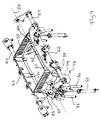
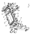
- the apparatus 37 partly shown in Fig. 4 includes an apparatus frame 38 with two opposed vertically extending frame walls 39, 40.
- a bin support 41 is provided in the form of a conveyor, a web pulling arrangement 42 placed above the support 41 and a cover raising and affixing device 43 placed between the web pulling arrangement and the bin support 41.
- the apparatus also includes a web supply and feeding mechanism 44 attached to the first frame wall 39.
- a rolled up continuous web 2 of cover elements is placed in the length supply and feeding mechanism 44.
- the web is fed upwards by means of a feeding roller 45 and a pressure roller 46 as well as additional rollers to the web pulling arrangement 42 in a way known per se, which is why this mechanism is not described any more detailed.
- the web pulling arrangement 42 includes a first movable gripping device 47, being placed movable along horizontal guides 48, 49 arranged between the two frame walls 39, 40.
- the first gripping device 47 is movable between a starting position shown in Figs. 4 and 5, where the first gripping device grips the leading edge of the web received from the web supply and feeding mechanism 44, and a delivering position not shown.
- the web pulling arrangement 42 includes a stationary gripping device 50 placed at a distance from the starting position of the first gripping device substantially corresponding to the length of a cover element forming part of the web.
- the second stationary gripping device 50 is adapted to grip the leading edge of the web when the first movable gripping device 47 is in its delivering position and has pulled out a length of the web substantially corresponding to the length of a cover element. Seen in the feeding direction of the web, a knife 51 for a transverse cutting of the web is placed on the foremost side of the movable gripping device 47. The knife 51 is movable together with the movable gripping device 47.
- the cover raising and affixing device 43 includes two opposed slides 52, 53 guided vertically movable along vertical guides 54, 55, which are fixedly connected to the second frame wall 40 and vertical guides 56, 57, which are fixedly connected to the first frame wall 39.
- a first cranked pivot arm 59 is mounted turnably about a first axis 58 and a second cranked pivot arm 60, which is turnable on a second axis 61, which is parallel to the first axis 58 and placed at a transverse distance therefrom.
- the pivot arms are placed and moved symmetrically in relation to a central longitudinal plane through the apparatus.
- the first pivot arm 59 has a cranked area 62
- the second pivot arm 60 has a cranked area 63. Due to the above symmetrical construction and movement of the pivot arms 59 and 60, below only the design of the first cranked pivot arm 59 will be described.
- On the first cranked area 62 of the first cranked pivot arm 59 three raising plates 64, 65, 66 are mounted turnably about their respective axes. By means of turning motors 67, 68, 69 the raising plates 64, 65, 66 can be turned to the starting position shown in Fig. 7, where they are adapted to be out of engagement with a cover element and the engagement position shown in Figs.
- the raising plates 64, 65, 66 are substantially placed in a common plane.
- the raising plates of the second pivot arm are also placed substantially in a common plane.
- the pivot arms 59, 60 are formed such that the extreme points of the raising plates 64, 65, 66, which are placed on said pivot arms, in their engagement position substantially lie in a row which coincides with the axis 58, 61 of the respective pivot arm 59, 60, such as shown in Fig. 8.
- the pivot arms 59, 60 are synchronously pivotal between the first position pivoted towards each other and shown in Fig. 7, where the raising plates 64, 65, 66 of the first pivot arm 59 substantially lie in the same plane as the raising plates of the second pivot arm 60, and a second position pivoted away from each other, which is shown in Figs. 8 to 10.
- the pivot arms are pivoted at least so much outwards that the planes, in which their respective raising plates lie, at least are substantially parallel.
- the pivot arms in the second position are pivoted so much outwards that the mentioned planes extend slightly incliningly upwards and inwards.
- a synchronising mechanism 70 placed at each of the slides 52, 53.
- said synchronising mechanism 70 consists of a block 71, which is placed slidably on a vertical guide 72, and which is movable in an upward and a downward direction by means of linear actuators 73, 74, and of connecting rods 75, 76, one end thereof being pivotally connected to the block 71 and the other end thereof being pivotally connected to the respective cranked pivot arm 59, 60.
- each spreading device 78 includes a slidable element 79, which is slidable in an upward and a downward direction in relation to the slide 72 along vertical guides 80, 81, which are firmly attached to the slide 53.
- the sliding of the slidable element 79 is effected by means of a linear actuator 82.
- Each spreading device 77, 78 further includes a spreading plate 83, which is turnably mounted on a transverse axis 84 and which can be turned on said axis by means of a linear actuator 85.
- a bin 22 (only shown in Fig. 10) is conveyed into a central position in the apparatus by means of the bin support, which is formed as a conveyor 41.
- the movable gripping device 47 in the web pulling arrangement 42 pulls or has pulled the leading edge of the web 2 from the starting position to the delivering position, where the second gripping device 50 has gripped the leading edge of the web, and the movable gripping device 47 has moved back to the starting position and has here gripped the web.
- the cover raising and affixing device 43 is moved upwards along the guides 48, 49 until the raising plates 64, 65, 66 of the pivot arms 59, 60 abut the lower surface of the web 2 between the inwardly folded sidewall sections 10, 11, the raising plates 64, 65, 66 of the pivot arms 59, 60 being in their retracted starting position, and the pivot arms 59, 60 being in their first position pivoted towards each other, cf. Fig. 7.
- the raising plates 64, 65, 66 of the first pivot arm 59 and the raising plates of the second pivot arm 60 are turned outwards and in between the inwardly folded sidewall section adjacent the cover element such as to engage with the inner side of the respective folded edge 12, 13 and further on to stretch the cover panel section 9 of the cover element in the transverse direction, cf. Fig. 7.
- the outer raising plates 64, 66 are brought into engagement with the adjacent end seams 14, 15, 16, 17, also obtaining a stretching of the cover panel section of the cover material in the longitudinal direction.
- the web 2 is cut transversely to separate the cover element from the web, the movable gripping device 47 at the end having a grip of the leading edge of the remaining web.
- a raising of the cover is effected. This is done by synchronously turning the pivot arms 59, 60 outwards, i.e. away from each other to the position shown in Fig. 8. In this position the cover provided by the cover element has a greater dimension than the upper area of the bin, as a both longitudinal and transverse stretching of the cover panel of the cover and the encasing skirt is effected.
- the spreading devices 77, 78 may now be moved upwards with the spreading plates 83 in their inwardly turned position. The spreading plates 83 may subsequently be turned outwards for a further stretching of the cover in the longitudinal direction such as shown in Figs. 9 and 10.
- the cover raising and affixing mechanism 43 is moved downwards until the cover panel of the cover abuts the upper edge of the bin and the skirt of the cover encases the upper area of the bin wall as shown in Fig. 10.
- the raising plates 64, 65, 66 are brought out of engagement with the circumferential wall of the cover 3 by turning them to their starting position.
- the cover raising and affixing device 43 may be moved further downwards.
- the spreading devices 77, 78 have been used, of course they are also moved downwards, so that the spreading plates 83 are brought out of engagement with the skirt of the cover.
- said cover when released by the cover raising and affixing device, is brought into encasing and securing engagement with the upper area of the bin to close its upper open end.
- the cover raising and affixing device 43 is moved upwards, and its pivot arms are turned inwards with a view to a new raising of a cover element and affixing of the cover provided hereby to a bin. Finally the bin, to which a cover has been affixed, is fed out of the apparatus by means of the bin support 41 formed as a conveyor.
- the provision and application of the spreading devices 77 and 78 as well as the application of the middle raising plate 65 of the pivot arms 59, 60 is optional and may depend on the length and width of the cover element and as a result hereof also on the length and the width of the bin onto which the cover element is to be placed.
Landscapes
- Engineering & Computer Science (AREA)
- Mechanical Engineering (AREA)
- Making Paper Articles (AREA)
- Folding Of Thin Sheet-Like Materials, Special Discharging Devices, And Others (AREA)
Applications Claiming Priority (1)
| Application Number | Priority Date | Filing Date | Title |
|---|---|---|---|
| DK200601225A DK200601225A (da) | 2006-09-22 | 2006-09-22 | Lågemne, som kan rejses til dannelse af et låg til påsætning på en kasses åbne ende |
Publications (1)
| Publication Number | Publication Date |
|---|---|
| EP1902957A1 true EP1902957A1 (fr) | 2008-03-26 |
Family
ID=38719272
Family Applications (1)
| Application Number | Title | Priority Date | Filing Date |
|---|---|---|---|
| EP07388068A Withdrawn EP1902957A1 (fr) | 2006-09-22 | 2007-09-21 | Couvercle en feuille; procédé et dispositif pour former un couvercle à partir d'une bande continue |
Country Status (2)
| Country | Link |
|---|---|
| EP (1) | EP1902957A1 (fr) |
| DK (1) | DK200601225A (fr) |
Cited By (2)
| Publication number | Priority date | Publication date | Assignee | Title |
|---|---|---|---|---|
| NL2023207B1 (en) * | 2019-05-27 | 2020-12-02 | Actitec B V | Device and method for close-fittingly arranging a cover over a box |
| WO2025219717A1 (fr) * | 2024-04-19 | 2025-10-23 | Detectamet Limited | Couverture de conteneur et son ensemble |
Citations (4)
| Publication number | Priority date | Publication date | Assignee | Title |
|---|---|---|---|---|
| US3017729A (en) * | 1959-05-26 | 1962-01-23 | Reynolds Metals Co | Shrinkable container closure and manufacture thereof |
| US4345413A (en) * | 1979-10-04 | 1982-08-24 | Sav-A-Stop Incorporated | Box lidding system and apparatus |
| DE3806512A1 (de) * | 1988-03-01 | 1989-09-14 | Winkler Duennebier Kg Masch | Verfahren und vorrichtung zum aufsetzen eines deckels auf eine schachtel |
| WO1996034798A1 (fr) * | 1995-05-03 | 1996-11-07 | Rembrandt Packaging B.V. | Procede de positionnement d'un couvercle rectangulaire sur une boite rectangulaire ouverte cote couvercle et dispositif de mise en application du procede |
-
2006
- 2006-09-22 DK DK200601225A patent/DK200601225A/da not_active Application Discontinuation
-
2007
- 2007-09-21 EP EP07388068A patent/EP1902957A1/fr not_active Withdrawn
Patent Citations (4)
| Publication number | Priority date | Publication date | Assignee | Title |
|---|---|---|---|---|
| US3017729A (en) * | 1959-05-26 | 1962-01-23 | Reynolds Metals Co | Shrinkable container closure and manufacture thereof |
| US4345413A (en) * | 1979-10-04 | 1982-08-24 | Sav-A-Stop Incorporated | Box lidding system and apparatus |
| DE3806512A1 (de) * | 1988-03-01 | 1989-09-14 | Winkler Duennebier Kg Masch | Verfahren und vorrichtung zum aufsetzen eines deckels auf eine schachtel |
| WO1996034798A1 (fr) * | 1995-05-03 | 1996-11-07 | Rembrandt Packaging B.V. | Procede de positionnement d'un couvercle rectangulaire sur une boite rectangulaire ouverte cote couvercle et dispositif de mise en application du procede |
Cited By (2)
| Publication number | Priority date | Publication date | Assignee | Title |
|---|---|---|---|---|
| NL2023207B1 (en) * | 2019-05-27 | 2020-12-02 | Actitec B V | Device and method for close-fittingly arranging a cover over a box |
| WO2025219717A1 (fr) * | 2024-04-19 | 2025-10-23 | Detectamet Limited | Couverture de conteneur et son ensemble |
Also Published As
| Publication number | Publication date |
|---|---|
| DK200601225A (da) | 2008-03-23 |
Similar Documents
| Publication | Publication Date | Title |
|---|---|---|
| US4078358A (en) | Bag-hanging and bag-filling machines adapted for synchronous and independent operation and method of using same | |
| US9463885B2 (en) | Bagging assembly | |
| CN211996366U (zh) | 一种全自动双工位套袋封口包装机 | |
| US8336404B2 (en) | Bale sampler | |
| CN105035409B (zh) | 机器人自动套箱设备及其使用方法 | |
| EP1812300B1 (fr) | Sac autoportant pour balles de matiere en bourre comprimee, et procede de confection du sac | |
| US20120096815A1 (en) | Method and device for filling a bag | |
| JP4491642B2 (ja) | 箱もの内容物の処理方法および処理装置 | |
| CN105109733B (zh) | 全自动连续拉伸真空气调包装机 | |
| US20140360135A1 (en) | Bags, Method of Making Bags and Method of Use Thereof for Enveloping Rectangular Bales | |
| EP0814021A1 (fr) | Machine d'emballage pour boîtes avec un sac à col | |
| CN112319936A (zh) | 图书包装设备和图书包装系统 | |
| EP1636094B1 (fr) | Procede systeme d'emballage d'objets dans un film tubulaire | |
| JP2021041559A (ja) | 内袋敷設装置 | |
| JP6847449B2 (ja) | 包装装置 | |
| JP2000153816A (ja) | 箱体の折り畳み処理方法及び装置 | |
| JP2724085B2 (ja) | 箱体からの内収容物取出装置 | |
| KR102112335B1 (ko) | 공간 확보형 식품 포장기 | |
| EP0117036A2 (fr) | Déballage de balles de tabac | |
| FI66566C (fi) | Anordning foer att mottaga och sidledes foerflytta tillplattade fyllningsaendar av paofyllda storsaeckar foer anordnande av saeckarnas tillslutning med sik-sakvikning | |
| US3981121A (en) | Machine for filling a sack with piece goods and closing mouth opening of the sack | |
| EP1462375A1 (fr) | Procédé et dispositif de vidange de sacs contenant des produits alimentaires liquides ou pâteux | |
| FR2471916A1 (fr) | Procede et dispositif pour presenter a la canule de remplissage d'une ensacheuse des sacs ouverts a leur partie superieure et pour tasser le contenu des sacs | |
| KR101598517B1 (ko) | 진공 포장장치 | |
| MXPA01011768A (es) | Procedimiento para levantar bolsas de empaque en hilera. |
Legal Events
| Date | Code | Title | Description |
|---|---|---|---|
| PUAI | Public reference made under article 153(3) epc to a published international application that has entered the european phase |
Free format text: ORIGINAL CODE: 0009012 |
|
| AK | Designated contracting states |
Kind code of ref document: A1 Designated state(s): AT BE BG CH CY CZ DE DK EE ES FI FR GB GR HU IE IS IT LI LT LU LV MC MT NL PL PT RO SE SI SK TR |
|
| AX | Request for extension of the european patent |
Extension state: AL BA HR MK YU |
|
| AKX | Designation fees paid |
Designated state(s): AT BE BG CH CY CZ DE DK EE ES FI FR GB GR HU IE IS IT LI LT LU LV MC MT NL PL PT RO SE SI SK TR |
|
| STAA | Information on the status of an ep patent application or granted ep patent |
Free format text: STATUS: THE APPLICATION IS DEEMED TO BE WITHDRAWN |
|
| 18D | Application deemed to be withdrawn |
Effective date: 20080927 |