EP1902982B1 - Module butée - Google Patents
Module butée Download PDFInfo
- Publication number
- EP1902982B1 EP1902982B1 EP06400031A EP06400031A EP1902982B1 EP 1902982 B1 EP1902982 B1 EP 1902982B1 EP 06400031 A EP06400031 A EP 06400031A EP 06400031 A EP06400031 A EP 06400031A EP 1902982 B1 EP1902982 B1 EP 1902982B1
- Authority
- EP
- European Patent Office
- Prior art keywords
- stop
- movement
- actuator
- drive
- module according
- Prior art date
- Legal status (The legal status is an assumption and is not a legal conclusion. Google has not performed a legal analysis and makes no representation as to the accuracy of the status listed.)
- Active
Links
Images


Classifications
-
- B—PERFORMING OPERATIONS; TRANSPORTING
- B23—MACHINE TOOLS; METAL-WORKING NOT OTHERWISE PROVIDED FOR
- B23Q—DETAILS, COMPONENTS, OR ACCESSORIES FOR MACHINE TOOLS, e.g. ARRANGEMENTS FOR COPYING OR CONTROLLING; MACHINE TOOLS IN GENERAL CHARACTERISED BY THE CONSTRUCTION OF PARTICULAR DETAILS OR COMPONENTS; COMBINATIONS OR ASSOCIATIONS OF METAL-WORKING MACHINES, NOT DIRECTED TO A PARTICULAR RESULT
- B23Q5/00—Driving or feeding mechanisms; Control arrangements therefor
- B23Q5/22—Feeding members carrying tools or work
- B23Q5/52—Limiting feed movement
-
- B—PERFORMING OPERATIONS; TRANSPORTING
- B65—CONVEYING; PACKING; STORING; HANDLING THIN OR FILAMENTARY MATERIAL
- B65G—TRANSPORT OR STORAGE DEVICES, e.g. CONVEYORS FOR LOADING OR TIPPING, SHOP CONVEYOR SYSTEMS OR PNEUMATIC TUBE CONVEYORS
- B65G47/00—Article or material-handling devices associated with conveyors; Methods employing such devices
- B65G47/74—Feeding, transfer, or discharging devices of particular kinds or types
- B65G47/88—Separating or stopping elements, e.g. fingers
- B65G47/8807—Separating or stopping elements, e.g. fingers with one stop
- B65G47/8823—Pivoting stop, swinging in or out of the path of the article
-
- B—PERFORMING OPERATIONS; TRANSPORTING
- B23—MACHINE TOOLS; METAL-WORKING NOT OTHERWISE PROVIDED FOR
- B23Q—DETAILS, COMPONENTS, OR ACCESSORIES FOR MACHINE TOOLS, e.g. ARRANGEMENTS FOR COPYING OR CONTROLLING; MACHINE TOOLS IN GENERAL CHARACTERISED BY THE CONSTRUCTION OF PARTICULAR DETAILS OR COMPONENTS; COMBINATIONS OR ASSOCIATIONS OF METAL-WORKING MACHINES, NOT DIRECTED TO A PARTICULAR RESULT
- B23Q16/00—Equipment for precise positioning of tool or work into particular locations not otherwise provided for
- B23Q16/001—Stops, cams, or holders therefor
-
- B—PERFORMING OPERATIONS; TRANSPORTING
- B23—MACHINE TOOLS; METAL-WORKING NOT OTHERWISE PROVIDED FOR
- B23Q—DETAILS, COMPONENTS, OR ACCESSORIES FOR MACHINE TOOLS, e.g. ARRANGEMENTS FOR COPYING OR CONTROLLING; MACHINE TOOLS IN GENERAL CHARACTERISED BY THE CONSTRUCTION OF PARTICULAR DETAILS OR COMPONENTS; COMBINATIONS OR ASSOCIATIONS OF METAL-WORKING MACHINES, NOT DIRECTED TO A PARTICULAR RESULT
- B23Q5/00—Driving or feeding mechanisms; Control arrangements therefor
- B23Q5/22—Feeding members carrying tools or work
- B23Q5/26—Fluid-pressure drives
-
- F—MECHANICAL ENGINEERING; LIGHTING; HEATING; WEAPONS; BLASTING
- F16—ENGINEERING ELEMENTS AND UNITS; GENERAL MEASURES FOR PRODUCING AND MAINTAINING EFFECTIVE FUNCTIONING OF MACHINES OR INSTALLATIONS; THERMAL INSULATION IN GENERAL
- F16F—SPRINGS; SHOCK-ABSORBERS; MEANS FOR DAMPING VIBRATION
- F16F9/00—Springs, vibration-dampers, shock-absorbers, or similarly-constructed movement-dampers using a fluid or the equivalent as damping medium
- F16F9/02—Springs, vibration-dampers, shock-absorbers, or similarly-constructed movement-dampers using a fluid or the equivalent as damping medium using gas only or vacuum
-
- B—PERFORMING OPERATIONS; TRANSPORTING
- B23—MACHINE TOOLS; METAL-WORKING NOT OTHERWISE PROVIDED FOR
- B23Q—DETAILS, COMPONENTS, OR ACCESSORIES FOR MACHINE TOOLS, e.g. ARRANGEMENTS FOR COPYING OR CONTROLLING; MACHINE TOOLS IN GENERAL CHARACTERISED BY THE CONSTRUCTION OF PARTICULAR DETAILS OR COMPONENTS; COMBINATIONS OR ASSOCIATIONS OF METAL-WORKING MACHINES, NOT DIRECTED TO A PARTICULAR RESULT
- B23Q2705/00—Driving working spindles or feeding members carrying tools or work
- B23Q2705/10—Feeding members carrying tools or work
- B23Q2705/12—Fluid-pressure drives
-
- B—PERFORMING OPERATIONS; TRANSPORTING
- B65—CONVEYING; PACKING; STORING; HANDLING THIN OR FILAMENTARY MATERIAL
- B65G—TRANSPORT OR STORAGE DEVICES, e.g. CONVEYORS FOR LOADING OR TIPPING, SHOP CONVEYOR SYSTEMS OR PNEUMATIC TUBE CONVEYORS
- B65G2205/00—Stopping elements used in conveyors to stop articles or arrays of articles
- B65G2205/06—Cushioned or damping stop devices, e.g. using springs or other mechanical actions
Definitions
- the invention relates to a stop module, in particular for automatic processing and conveying devices, with a arranged on a base unit stop member for itself in a movement plane in a current working movement direction moving objects, which by means of an actuator between a located in the plane of movement stop position and lying below the plane of movement Release position is movable, wherein a guide device is provided, with at least one guide track on which the stop member is forcibly guided at a first location between the stop position and the release position, wherein the stop member is pivotally connected at such a second location remote from the first location with an actuating element in that during a lowering movement of the stop member from the stop position to the release position, the stop member is pivoted in the direction of movement of the work, wherein the actuator has force Translation means is coupled in the form of a lever device with the stop member.
- a stop module In the US 5,154,277 is also a stop module disclosed. It is here provided a base body having two stop pawls.
- the main body has two guide grooves, which are in engagement with two guide pins.
- a contact surface for a roller At the bottom of the body, a contact surface for a roller is provided, which runs on it. The role is on a lever, which in turn is connected to a fluid-operated cylinder.
- one of the pawls is swiveled away in the working movement direction from the path of movement of the objects.
- a stop module is also from the EP 0 484 648 known.
- the stop described there is by means of a pneumatically actuable actuating piston out of the path of movement approaching workpieces and moved back into this.
- a compressed air connection is provided on the housing, via which compressed air is supplied.
- the stopper is associated with a damping device, so that the movement of the struck workpieces can be damped.
- automatic processing and conveying devices for which the stop module is preferably used, constantly in operation, so that a tarnished object is pressed in the direction of movement of the work on the stop member. Due to the contact force exerted by the object on the stop member, not inconsiderable friction arises during the lowering movement of the stop member. The force to be exerted by the actuator for lowering the stop member is correspondingly large.
- the object of the invention is to provide a stop module of the type mentioned, in which the lowering of the stop member with less effort is possible.
- the stop module according to the invention is characterized in that a drive force generated by the actuator can be translated into a tappable on the stopper larger force, the lever means a first lever which is articulated on the one hand mounted on the actuator and linearly displaceable and on the other hand articulated to a second lever , Wherein the latter is pivotally mounted on the one hand to a stationary pivot axis formed on the base unit and on the other hand articulated on the stop member.
- the guideway extends at least partially obliquely to the plane of movement of the objects. This makes it possible to impose an obliquely directed lowering movement on the stop member at its first location.
- the guideway vertically, ie perpendicular to the plane of movement.
- the stop member at the second point would have to be pivotally connected to the actuating element, so that it pivots away at the taking place in the first place vertical downward movement about the first point in the working movement direction.
- the stop member at its upper end on a stop contour for the objects, which passes through a trajectory in the movement of the stop member between the stop position and the release position, in particular above the plane of movement in the working direction.
- the contact between the impacted article and stop member is suitably linear, but may also be sheet-like.
- the guide device has a slotted guide, with at least one guide slot arranged on the basic unit, in which at least one guide member formed on the stop member at the first location is forced.
- the guide slot can be formed by a guide groove and the guide member of a guide pin.
- a dampening device connected to the stop member is provided for damped movement of the stop member from an advance stop position in the working movement direction before the stop position to the stop position.
- the stop member can be brought in its downward movement from the stop position to the release position by the course of the guideway in a position so that it again assumes its predicted position in the subsequent upward movement.
- the actuator is coupled via force transmission means with the stop member, wherein a drive force generated by the actuator is translatable into a tappable on the stopper larger force.
- the power transmission means are formed by a lever transmission.
- a lever device which is connected to the stop member, with a first lever which is articulated on the one hand on the actuator and linearly displaceable and on the other hand articulated on a second lever designed as an actuating element, the latter on the one hand to one of the base unit formed, stationary pivot axis is pivotable and on the other hand articulated mounted on the stop member.
- the actuator has a drive element for generating a parallel to the plane of movement directed linear drive movement, which is implemented via Umsetzstoff held in an occurring between the stop position and the release position of the stop member stop member movement.
- the drive movement takes place in the vertical direction, i. perpendicular to the plane of motion.
- the stroke of the drive element thus extends in the vertical direction and thus significantly affects the overall height of the drive module.
- the effects on the overall height are much smaller when the linear drive movement is parallel to the plane of movement.
- the drive element is arranged to be linearly displaceable in a drive mount formed parallel to the movement plane in the base unit.
- the actuator is arranged with its longitudinal side aligned substantially parallel to the plane of movement in the drive receiving.
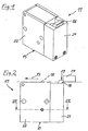
- FIGS. 1 to 7 show a first embodiment of the stop module 11 according to the invention, which will be explained below by way of example with reference to such a damping device 12. However, it is also possible to use a stop module without damping device.
- the stop module 11 is preferably used in automatic processing and conveying devices 70, in order to separate in a movement plane 18 in a working movement direction 13 moving objects 14, such as workpieces or the like. After separation, the articles 14 can then be treated individually, for example processed, diverted, etc.
- the stop module 11 has an example cuboidal base unit 15, on which a stop member 16 is arranged, which is movable by means of an actuator 17 from the plane of movement 18 of the articles 14 and back into this. Furthermore, the already mentioned damping device 12 is also provided, by means of which the stop member 16 is damped by a lying in working movement direction 13 before a stop position 20 Voranschlag too 19 to the stop position 20.
- the base unit 15 consists of a stop member carrier 21, in which the stop member 16 is housed in the manner described in more detail below, and an actuator carrier 22 formed separately from the stop member carrier 21.
- a one-piece constructed basic unit 15 is conceivable.
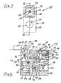
- an electric linear drive in the form of an electromagnet drive is provided as an actuator 17, an electric linear drive in the form of an electromagnet drive.
- the electromagnet drive has a currentable electromagnet 23, in particular U-shaped yoke, in which a drive element 24 is guided in a linearly displaceable manner in the form of an armature.
- the armature When energizing the electromagnet, the armature is attracted to the yoke, whereby a tappable drive movement is generated.
- the drive movement takes place parallel to the movement plane 18 of the objects 14 and is transmitted via Umsetzstoffsch in the manner described in more detail below on the stop member 16, which is movable between its stop position 20 and a lying below the plane of movement release position 25.
- the trained as an anchor drive element 24 is also still performed linearly in a formed in the base unit 15, in particular in the actuator support 22 drive receptacle 26.
- the electromagnet 23 is also arranged with the longitudinal axis aligned substantially parallel to the plane of movement 18 in the drive mount 26.
- the linear drive movement generated parallel to the movement plane 18 has the advantage that the travel or stroke of the drive element 24 extends in the horizontal direction and thus does not affect the overall height of the stop module 11. Also, the electromagnet 23 has by its horizontal position relatively little influence on the height.
- a further reduction in the overall height and even the overall size of the stop module 11 can be achieved by using relatively small-sized actuators 17 in combination with conversion means in the form of force translating means, so that a relatively small driving force generated by the actuator 17 is sufficient to move the drive member, as this is translated into a higher power via the power translation.
- a lever transmission is provided, with a lever device 27 which is formed between the armature of the electromagnet 23 and the stop member 16.
- the lever device 27 has a first lever 28, which is pivotally connected on the one hand about a first pivot axis 29 on the armature and on the other hand about a second pivot axis 30 with a second lever 31.
- this is at the anchor a slot-like opening 32 for receiving the end of the first lever 28, wherein in turn at its turn a passage opening 33 is provided at the end of the lever, through which a bolt 34 is passed.
- the bolt 34 in turn is rotatably mounted on the armature and thus forms the first pivot axis 29.
- the pivot bearing at the opposite end of the lever lever 28 may be carried out in a similar manner.
- the second lever 31 is pivotally mounted on the one hand on a fixed to the base unit 15 fixed third pivot axis 35 and on the other hand connected at a second point 36 via a fourth pivot axis 37 pivotally connected to the stop member 16.
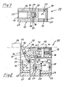
- the second lever 31 is formed by a damping cylinder 38 of the damping device 12.
- This has a cylinder chamber 40, in which a damping piston 39 is displaceably guided and sealed by a piston sealing device 41 against the wall of the cylinder chamber 40.
- the damping piston 39 is connected to a piston rod 42 via fastening means, for example by means of a screw 43. It is of course also possible to have one one-piece connection between damping piston 39 and piston rod 42 provided.
- the piston rod 42 As mentioned pivotally connected to the stop member 16. It thus represents the actuating element for the stop member 16.
- the cylinder chamber 40 is closed with a cover 44.
- a throttle device 45 which forms a flow resistance for the outflowing in the piston movement via a channel, not shown air.
- the damping effect adjustment means 46 for example, provided in a cover channel 47 movably guided adjusting screw, with which the Ausströmquerites for the outflowing air can either narrow or extend, which in turn increases or decreases the throttling effect, the latter in turn the damping effect certainly.
- the adjusting screw in direction "+" increases the damping effect, while turning the adjusting screw in the direction "-" the damping effect is reduced.
- the stop member 16 is pivotally connected to the piston rod 42 at a second location 36.
- a guide means 48 is provided, with at least one guide track 49 on which the stop member 16 is forcibly guided at a first location 50 between the stop position 16 and the release position 25.
- the guide means 48 on a slotted guide, with two formed on the base unit guide slots in the form of guide grooves 51 in which a formed on the stop member 16 Guiding member in the form of a guide pin 52 is positively guided.
- the guide pin 52 can pivot in the guide grooves 51.
- the guide grooves 51 each have a head portion 53, which extends substantially vertically, ie perpendicular to the plane of movement 18.
- This head portion 53 is required because already during the movement of the stop member 16 from the Voranschlag too 19 in the stop position 20, a pivoting of the stop member 16 takes place at the second point 36 about the fourth pivot axis 37, wherein due to the fact that designed as an actuating element Piston rod 42 is forcibly guided utznunver sourcelich by the damping piston 39 in the cylinder chamber 40, the stop member 16 is pressed down a little way.
- the head area 53 is adjoined with a radius by a guide area 54, which extends obliquely downwards counter to the working movement direction 13.
- the operation of the stop module is that a coming from the right object 14, which may for example also be a workpiece, in particular machine part or the like, first reaches the Voranschlag too 19 of the stop member 16.
- a self-locking of the stop member 16 is present such that it can not be pressed down without actuation of the actuator 17.
- the stop member 16 is pivoted in the working movement direction 13 about the fourth pivot axis 37 and indeed so far until the damping piston 39 strikes the rear wall of the cover 44, and thus all air in the cylinder chamber 40 is ejected. A Further movement of the damping piston 39 in the working movement direction 13 is no longer possible, so that in this way the stop position 20 is fixed. As in particular in Figure 10A shown, the rear side of the stop member 16 is spaced in the stop position 20 at the distance a from the actuator support 22 of the base unit 15. If the object 14 is to continue its movement in the working movement direction 13, then the actuator 17 is activated, in the case of the first embodiment the electromagnet is energized, so that the armature is attracted.
- FIG. 8 shows a second embodiment of the stop module 11 according to the invention, which differs from the first embodiment in that instead of an electric linear drive, a fluidic linear drive is used.
- a fluidic linear drive is used.
- a pneumatic linear drive is used.
- a drive element 24 is provided in the form of a drive piston, which is guided linearly displaceable in the drive housing 26.
- the drive piston is then articulated again in the manner already described above, the first lever 28.
- To drive the drive piston for the purpose of lowering the stop member 16 the first lever 28 facing the piston side is acted upon via a feed channel 57 with compressed air, causing the drive piston moves in the direction 13 Pakistanfarsraum.
- the drive receptacle 26 is closed with a cover 58, so that a piston chamber is formed, in which the drive piston is guided.
- the opposite side of the piston is pressurized with compressed air.
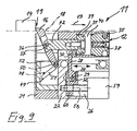
- FIG. 9 shows a third embodiment of the drive module 11 according to the invention, which differs from the embodiments described above in that an electric rotary linear drive in the form of a spindle drive is used.
- the spindle drive has a rotatably driven drive element 24 in the form of a spindle nut, which is mounted at the same time parallel to the plane of movement 18 linearly displaceable on the spindle motor 59.
- On the spindle nut 58 is a driver 60 which is also linearly displaced by the linear displacement of the spindle nut 58.
- the first lever 28 is articulated.
Landscapes
- Engineering & Computer Science (AREA)
- Mechanical Engineering (AREA)
- General Engineering & Computer Science (AREA)
- Vibration Prevention Devices (AREA)
- Special Conveying (AREA)
- Transmission Devices (AREA)
- Container, Conveyance, Adherence, Positioning, Of Wafer (AREA)
- Input Circuits Of Receivers And Coupling Of Receivers And Audio Equipment (AREA)
- Control Of Motors That Do Not Use Commutators (AREA)
- Encapsulation Of And Coatings For Semiconductor Or Solid State Devices (AREA)
- Reciprocating Conveyors (AREA)
- Automatic Assembly (AREA)
Claims (9)
- Module de butée, en particulier pour des dispositifs automatiques de convoyage et de traitement, comportant un organe de butée (16) pour des objets (14) défilant dans un plan de défilement (18) dans une direction de travail (13) actuelle, lequel est disposé sur une unité de base (15) et est apte à se déplacer au moyen d'un composant de réglage (17) entre une position de butée (20) située dans le plan de défilement (18) et une position de déblocage (25) située en dessous du plan de défilement (18), sachant qu'il est prévu un dispositif de guidage (48) avec au moins une voie de guidage (49) sur laquelle l'organe de butée (16) au niveau d'un premier emplacement (50) subit un guidage forcé entre la position de butée (20) et la position de déblocage (25), l'organe de butée (16), au niveau d'un deuxième emplacement (36) éloigné du premier emplacement (50), étant relié à un élément de réglage de manière à pouvoir pivoter, de telle sorte que, lorsque l'organe de butée (16) est déplacé vers le bas depuis la position de butée (20) dans la position de déblocage (25), l'organe de butée (16) pivote dans la direction de travail (13), le composant de réglage (17) étant couplé à l'organe de butée (16) par des moyens de transmission de force formés par un dispositif de levier (27), caractérisé en ce qu'une force d'actionnement, générée par le composant de réglage (17), peut être transformée en une force plus grande pouvant être prélevée sur l'organe de butée (16), le dispositif de levier (27) comportant un premier levier (28) qui, sur un côté, est monté de manière articulée contre le composant de réglage (17) et est mobile linéairement et, sur l'autre côté, est monté de manière articulée sur un deuxième levier (31), ce dernier étant, d'une part, apte à pivoter autour d'un axe de pivotement (35) stationnaire, réalisé sur l'unité de base (15) et, d'autre part, monté de manière articulée sur l'organe de butée (16).
- Module de butée selon la revendication 1, caractérisé en ce que la voie de guidage (49), en partie au moins, est inclinée par rapport au plan de défilement (18).
- Module de butée selon la revendication 1 ou 2, caractérisé en ce que l'organe de butée (16) possède, au niveau de son extrémité supérieure, un contour de butée qui passe à travers une courbe (75) au moment du déplacement de l'organe de butée (16) entre la position de butée (20) et la position de déblocage (25).
- Module de butée selon l'une quelconque des revendications précédentes, caractérisé en ce que le dispositif de guidage (48) comporte une glissière à coulisse avec au moins une coulisse de guidage, qui est réalisée dans l'unité de base (15) et dans laquelle au moins un composant de guidage, disposé sur l'organe de butée (16), subit un guidage forcé.
- Module de butée selon l'une quelconque des revendications précédentes, caractérisé par un dispositif d'amortissement (12), relié à l'organe de butée (16), en vue d'un déplacement amorti de l'organe de butée depuis une position de butée préliminaire (19), située en amont de la position de butée (20) par référence à la direction de travail (13), jusque dans la position de butée (20).
- Module de butée selon l'une quelconque des revendications précédentes, caractérisé en ce que le deuxième levier est formé par un cylindre d'amortissement (38) du dispositif d'amortissement (12).
- Module de butée selon l'une quelconque des revendications précédentes, caractérisé en ce que le composant de réglage (17) comporte un actionneur (24) destiné à générer un mouvement d'actionnement linéaire, qui est orienté parallèlement au plan de défilement (18) et qui, par des moyens de transformation, peut être transformé en un mouvement vers le haut ou le bas se produisant entre la position de butée (20) et la position de déblocage (25) de l'organe de butée.
- Module de butée selon la revendication 7, caractérisé en ce que l'actionneur (24) est disposé de manière mobile linéairement dans un logement (26) réalisé dans l'unité de base (15) parallèlement au plan de défilement (18).
- Module de butée selon la revendication 8, caractérisé en ce que le composant de réglage (17) est disposé dans le logement (26) en étant orienté avec son côté longitudinal sensiblement parallèlement au plan de défilement (18).
Priority Applications (6)
| Application Number | Priority Date | Filing Date | Title |
|---|---|---|---|
| EP06400031A EP1902982B1 (fr) | 2006-09-25 | 2006-09-25 | Module butée |
| DE502006002135T DE502006002135D1 (de) | 2006-09-25 | 2006-09-25 | Anschlagmodul |
| AT06400031T ATE414662T1 (de) | 2006-09-25 | 2006-09-25 | Anschlagmodul |
| KR1020070096564A KR100996222B1 (ko) | 2006-09-25 | 2007-09-21 | 접촉 모듈 |
| US11/861,040 US7513355B2 (en) | 2006-09-25 | 2007-09-25 | Abutment module |
| CN2007101612236A CN101152929B (zh) | 2006-09-25 | 2007-09-25 | 止动组件 |
Applications Claiming Priority (1)
| Application Number | Priority Date | Filing Date | Title |
|---|---|---|---|
| EP06400031A EP1902982B1 (fr) | 2006-09-25 | 2006-09-25 | Module butée |
Publications (2)
| Publication Number | Publication Date |
|---|---|
| EP1902982A1 EP1902982A1 (fr) | 2008-03-26 |
| EP1902982B1 true EP1902982B1 (fr) | 2008-11-19 |
Family
ID=37708168
Family Applications (1)
| Application Number | Title | Priority Date | Filing Date |
|---|---|---|---|
| EP06400031A Active EP1902982B1 (fr) | 2006-09-25 | 2006-09-25 | Module butée |
Country Status (6)
| Country | Link |
|---|---|
| US (1) | US7513355B2 (fr) |
| EP (1) | EP1902982B1 (fr) |
| KR (1) | KR100996222B1 (fr) |
| CN (1) | CN101152929B (fr) |
| AT (1) | ATE414662T1 (fr) |
| DE (1) | DE502006002135D1 (fr) |
Cited By (2)
| Publication number | Priority date | Publication date | Assignee | Title |
|---|---|---|---|---|
| DE102016219966A1 (de) * | 2016-10-13 | 2018-04-19 | Asutec Gmbh | Anschlagmodul |
| DE102018102172A1 (de) | 2018-01-31 | 2019-08-01 | Eto Magnetic Gmbh | Elektromagnetische Stellvorrichtung mit Befestigungsmittel |
Families Citing this family (16)
| Publication number | Priority date | Publication date | Assignee | Title |
|---|---|---|---|---|
| DE102007062076A1 (de) * | 2007-12-21 | 2009-06-25 | Robert Bosch Gmbh | Anschlagmodul, insbesondere für automatisierte Bearbeitungs- und Fördereinrichtungen |
| DE102010056035A1 (de) | 2010-12-15 | 2012-06-21 | Wörner Automatisierungstechnik GmbH | Anschlagmodul zum positionsgenauen Anhalten eines Werkstücks |
| DE102010056036A1 (de) | 2010-12-15 | 2012-06-21 | Wörner Automatisierungstechnik GmbH | Anschlagmodul zum positionsgenauen Anhalten eines Werkstücks |
| JP5698345B2 (ja) * | 2011-03-23 | 2015-04-08 | 平田機工株式会社 | 停止装置及び停止解除方法 |
| WO2012127530A1 (fr) * | 2011-03-23 | 2012-09-27 | 平田機工株式会社 | Dispositif d'arrêt et procédé de libération de l'arrêt |
| CN102416577A (zh) * | 2011-12-19 | 2012-04-18 | 贵州航天控制技术有限公司 | 一种防撞定位止动机构 |
| WO2013144997A1 (fr) * | 2012-03-27 | 2013-10-03 | 平田機工株式会社 | Dispositif d'arrêt et procédé d'arrêt temporaire |
| DE102012103820B3 (de) * | 2012-05-02 | 2013-08-08 | Wörner Automatisierungstechnik GmbH | Anschlagmodul zum positionsgenauen Anhalten eines Gegenstandes |
| DE102013015525B4 (de) * | 2013-09-18 | 2019-10-24 | Asutec Gmbh | Anschlagmodul |
| JP6276052B2 (ja) | 2014-02-10 | 2018-02-07 | 平田機工株式会社 | 停止装置及び補助停止ユニット |
| DE102014110822B4 (de) | 2014-07-30 | 2016-10-27 | Wörner Automatisierungstechnik GmbH | Anschlagmodul zum positionsgenauen Anhalten eines Gegenstands |
| DE102017104151B3 (de) * | 2017-02-28 | 2018-03-15 | Wörner Automatisierungstechnik GmbH | Anschlagmodul zum positionsgenauen Anhalten eines Gegenstands |
| WO2018222887A1 (fr) * | 2017-06-01 | 2018-12-06 | Usnr, Llc. | Ensemble de superposition |
| MX2020002722A (es) * | 2017-09-13 | 2020-11-06 | Flexlink Ab | Dispositivo de freno para un sistema transportador. |
| DE102020106906B4 (de) | 2020-03-13 | 2021-10-28 | FAB Fördertechnik und Anlagenbau GmbH | Stoppervorrichtung für ein Fördermittel zum Fördern von Stückgut, beispielsweise für einen Rollenförderer oder einen Bandförderer |
| WO2022260573A1 (fr) * | 2021-06-08 | 2022-12-15 | Flexlink Ab | Dispositif d'arrêt pour un système de convoyeur et système de convoyeur comprenant un dispositif d'arrêt |
Family Cites Families (13)
| Publication number | Priority date | Publication date | Assignee | Title |
|---|---|---|---|---|
| DE3003674C2 (de) * | 1980-02-01 | 1986-10-30 | Seitz Enzinger Noll Maschinenbau Ag, 6800 Mannheim | Vorrichtung zum Stoppen oder Wenden von Flaschenkästen |
| JPS58188229A (ja) * | 1982-04-26 | 1983-11-02 | Mazda Motor Corp | 搬送機の定位置停止装置 |
| DE9015950U1 (de) | 1990-11-07 | 1991-02-14 | Wörner, Helmut, 7306 Denkendorf | Anschlag mit einer Dämpfungseinrichtung |
| JPH0497731U (fr) * | 1991-01-22 | 1992-08-24 | ||
| US5168976A (en) * | 1992-02-14 | 1992-12-08 | Newcor, Inc. | Cushioned stop for powered conveyor |
| US5211276A (en) * | 1992-06-23 | 1993-05-18 | Tekno Inc. | Stop for conveyor |
| DE19543797A1 (de) * | 1995-11-24 | 1997-05-28 | Grob Gmbh & Co Kg | Vorrichtung für die Steuerung einer Palette auf einer Förderbahn |
| US6119843A (en) | 1999-02-03 | 2000-09-19 | Robinson; Brian Owen | Retractable stop assembly |
| US6112877A (en) * | 1999-03-22 | 2000-09-05 | Dallas A. C. Horn & Co. | Decelerator for large conveyors |
| US6763930B2 (en) * | 2002-03-14 | 2004-07-20 | Rapistan Systems Advertising Corp. | Accumulation conveyor assembly |
| FR2856998A1 (fr) * | 2003-05-19 | 2005-01-07 | Robotiques 3 Dimensions | Butee escamotable |
| DE20315815U1 (de) * | 2003-10-10 | 2005-02-17 | Grob-Werke Burkhart Grob E.K. | Vorrichtung zum Stoppen von Transportgut |
| DE502005001686D1 (de) * | 2005-07-19 | 2007-11-22 | Helmut Woerner | Anschlag- und Dämpfermodul |
-
2006
- 2006-09-25 DE DE502006002135T patent/DE502006002135D1/de active Active
- 2006-09-25 AT AT06400031T patent/ATE414662T1/de active
- 2006-09-25 EP EP06400031A patent/EP1902982B1/fr active Active
-
2007
- 2007-09-21 KR KR1020070096564A patent/KR100996222B1/ko active Active
- 2007-09-25 US US11/861,040 patent/US7513355B2/en active Active
- 2007-09-25 CN CN2007101612236A patent/CN101152929B/zh active Active
Cited By (4)
| Publication number | Priority date | Publication date | Assignee | Title |
|---|---|---|---|---|
| DE102016219966A1 (de) * | 2016-10-13 | 2018-04-19 | Asutec Gmbh | Anschlagmodul |
| DE102016219966B4 (de) | 2016-10-13 | 2019-12-19 | Asutec Gmbh | Anschlagmodul |
| DE102018102172A1 (de) | 2018-01-31 | 2019-08-01 | Eto Magnetic Gmbh | Elektromagnetische Stellvorrichtung mit Befestigungsmittel |
| DE102018102172B4 (de) | 2018-01-31 | 2024-08-22 | Eto Magnetic Gmbh | Elektromagnetische Stellvorrichtung mit Befestigungsmittel |
Also Published As
| Publication number | Publication date |
|---|---|
| KR100996222B1 (ko) | 2010-11-24 |
| KR20080027744A (ko) | 2008-03-28 |
| CN101152929B (zh) | 2012-01-11 |
| US20080073180A1 (en) | 2008-03-27 |
| EP1902982A1 (fr) | 2008-03-26 |
| CN101152929A (zh) | 2008-04-02 |
| ATE414662T1 (de) | 2008-12-15 |
| US7513355B2 (en) | 2009-04-07 |
| DE502006002135D1 (de) | 2009-01-02 |
Similar Documents
| Publication | Publication Date | Title |
|---|---|---|
| EP1902982B1 (fr) | Module butée | |
| EP1902981B1 (fr) | Module butée | |
| EP1967472B1 (fr) | Module de butée et amortissement | |
| EP1970139B1 (fr) | Dispositif de prise destiné à la saisie et à la fixation de pièces usinées, en particuliers pour cintreuses | |
| AT514930B1 (de) | Hinteranschlageinheit für Biegemaschine | |
| EP2465637B1 (fr) | Dispositif de retenue de pièce usinée pour la fixation d'une pièce usinée de type plaque, notamment d'une tôle, sur une unité de déplacement de pièce usinée d'une machine-outil | |
| DE19543797A1 (de) | Vorrichtung für die Steuerung einer Palette auf einer Förderbahn | |
| DE102017212660A1 (de) | Saugvorrichtung | |
| EP3239567A1 (fr) | Robinet a vanne avec guidage curviligne | |
| DE102013015525B4 (de) | Anschlagmodul | |
| EP1674197B1 (fr) | Dispositif d'alimentation des panneaux | |
| DE60217851T2 (de) | Fadenklemme für eine webmaschine und webmaschine mit einer solchen fadenklemme | |
| DE3528337A1 (de) | Spannvorrichtung | |
| EP1746054B1 (fr) | Module butée avec entrainement par moteur electrique | |
| DE102006028493A1 (de) | Anhaltevorrichtung | |
| DE1483579B1 (de) | Vorrichtung zur Entlueftung von Giessformen an Druckgiessmaschinen | |
| EP0107763B1 (fr) | Etau, en particulier pour machine-outil | |
| DE10213850C1 (de) | Matritzenseitige Auswerfvorrichtung für Werkstücke bei Ein- und Mehrstufenpressen | |
| DE102012103823B4 (de) | Anschlagmodul zum positionsgenauen Anhalten eines Gegenstands | |
| DE3329942C1 (de) | Spannvorrichtung für insbes. spanabhebend zu bearbeitende Werkstücke | |
| WO2001087512A1 (fr) | Unite de transfert et son procede de commande | |
| EP1545808A1 (fr) | Machine a cintrer | |
| EP0873205B1 (fr) | Machine a plier | |
| DE10007255A1 (de) | Einrichtung zum stempelseitigen Auswerfen von Werkstücken für Ein- oder Mehrstufenpressen | |
| EP0297470A2 (fr) | Butée actionnée pneumatiquement pour pièces à déplacer |
Legal Events
| Date | Code | Title | Description |
|---|---|---|---|
| PUAI | Public reference made under article 153(3) epc to a published international application that has entered the european phase |
Free format text: ORIGINAL CODE: 0009012 |
|
| 17P | Request for examination filed |
Effective date: 20070419 |
|
| AK | Designated contracting states |
Kind code of ref document: A1 Designated state(s): AT BE BG CH CY CZ DE DK EE ES FI FR GB GR HU IE IS IT LI LT LU LV MC NL PL PT RO SE SI SK TR |
|
| AX | Request for extension of the european patent |
Extension state: AL BA HR MK YU |
|
| GRAP | Despatch of communication of intention to grant a patent |
Free format text: ORIGINAL CODE: EPIDOSNIGR1 |
|
| GRAS | Grant fee paid |
Free format text: ORIGINAL CODE: EPIDOSNIGR3 |
|
| GRAA | (expected) grant |
Free format text: ORIGINAL CODE: 0009210 |
|
| AK | Designated contracting states |
Kind code of ref document: B1 Designated state(s): AT BE BG CH CY CZ DE DK EE ES FI FR GB GR HU IE IS IT LI LT LU LV MC NL PL PT RO SE SI SK TR |
|
| REG | Reference to a national code |
Ref country code: GB Ref legal event code: FG4D Free format text: NOT ENGLISH |
|
| REG | Reference to a national code |
Ref country code: CH Ref legal event code: EP Ref country code: CH Ref legal event code: NV Representative=s name: TROESCH SCHEIDEGGER WERNER AG |
|
| AKX | Designation fees paid |
Designated state(s): AT BE BG CH CY CZ DE DK EE ES FI FR GB GR HU IE IS IT LI LT LU LV MC NL PL PT RO SE SI SK TR |
|
| REG | Reference to a national code |
Ref country code: IE Ref legal event code: FG4D Free format text: LANGUAGE OF EP DOCUMENT: GERMAN |
|
| REF | Corresponds to: |
Ref document number: 502006002135 Country of ref document: DE Date of ref document: 20090102 Kind code of ref document: P |
|
| LTIE | Lt: invalidation of european patent or patent extension |
Effective date: 20081119 |
|
| PG25 | Lapsed in a contracting state [announced via postgrant information from national office to epo] |
Ref country code: LT Free format text: LAPSE BECAUSE OF FAILURE TO SUBMIT A TRANSLATION OF THE DESCRIPTION OR TO PAY THE FEE WITHIN THE PRESCRIBED TIME-LIMIT Effective date: 20081119 Ref country code: ES Free format text: LAPSE BECAUSE OF FAILURE TO SUBMIT A TRANSLATION OF THE DESCRIPTION OR TO PAY THE FEE WITHIN THE PRESCRIBED TIME-LIMIT Effective date: 20090301 |
|
| NLV1 | Nl: lapsed or annulled due to failure to fulfill the requirements of art. 29p and 29m of the patents act | ||
| PG25 | Lapsed in a contracting state [announced via postgrant information from national office to epo] |
Ref country code: PL Free format text: LAPSE BECAUSE OF FAILURE TO SUBMIT A TRANSLATION OF THE DESCRIPTION OR TO PAY THE FEE WITHIN THE PRESCRIBED TIME-LIMIT Effective date: 20081119 Ref country code: NL Free format text: LAPSE BECAUSE OF FAILURE TO SUBMIT A TRANSLATION OF THE DESCRIPTION OR TO PAY THE FEE WITHIN THE PRESCRIBED TIME-LIMIT Effective date: 20081119 Ref country code: IS Free format text: LAPSE BECAUSE OF FAILURE TO SUBMIT A TRANSLATION OF THE DESCRIPTION OR TO PAY THE FEE WITHIN THE PRESCRIBED TIME-LIMIT Effective date: 20090319 Ref country code: SI Free format text: LAPSE BECAUSE OF FAILURE TO SUBMIT A TRANSLATION OF THE DESCRIPTION OR TO PAY THE FEE WITHIN THE PRESCRIBED TIME-LIMIT Effective date: 20081119 Ref country code: LV Free format text: LAPSE BECAUSE OF FAILURE TO SUBMIT A TRANSLATION OF THE DESCRIPTION OR TO PAY THE FEE WITHIN THE PRESCRIBED TIME-LIMIT Effective date: 20081119 Ref country code: FI Free format text: LAPSE BECAUSE OF FAILURE TO SUBMIT A TRANSLATION OF THE DESCRIPTION OR TO PAY THE FEE WITHIN THE PRESCRIBED TIME-LIMIT Effective date: 20081119 |
|
| REG | Reference to a national code |
Ref country code: IE Ref legal event code: FD4D |
|
| PG25 | Lapsed in a contracting state [announced via postgrant information from national office to epo] |
Ref country code: EE Free format text: LAPSE BECAUSE OF FAILURE TO SUBMIT A TRANSLATION OF THE DESCRIPTION OR TO PAY THE FEE WITHIN THE PRESCRIBED TIME-LIMIT Effective date: 20081119 Ref country code: DK Free format text: LAPSE BECAUSE OF FAILURE TO SUBMIT A TRANSLATION OF THE DESCRIPTION OR TO PAY THE FEE WITHIN THE PRESCRIBED TIME-LIMIT Effective date: 20081119 Ref country code: BG Free format text: LAPSE BECAUSE OF FAILURE TO SUBMIT A TRANSLATION OF THE DESCRIPTION OR TO PAY THE FEE WITHIN THE PRESCRIBED TIME-LIMIT Effective date: 20090219 Ref country code: IE Free format text: LAPSE BECAUSE OF FAILURE TO SUBMIT A TRANSLATION OF THE DESCRIPTION OR TO PAY THE FEE WITHIN THE PRESCRIBED TIME-LIMIT Effective date: 20081119 Ref country code: RO Free format text: LAPSE BECAUSE OF FAILURE TO SUBMIT A TRANSLATION OF THE DESCRIPTION OR TO PAY THE FEE WITHIN THE PRESCRIBED TIME-LIMIT Effective date: 20081119 |
|
| PG25 | Lapsed in a contracting state [announced via postgrant information from national office to epo] |
Ref country code: PT Free format text: LAPSE BECAUSE OF FAILURE TO SUBMIT A TRANSLATION OF THE DESCRIPTION OR TO PAY THE FEE WITHIN THE PRESCRIBED TIME-LIMIT Effective date: 20090420 Ref country code: CZ Free format text: LAPSE BECAUSE OF FAILURE TO SUBMIT A TRANSLATION OF THE DESCRIPTION OR TO PAY THE FEE WITHIN THE PRESCRIBED TIME-LIMIT Effective date: 20081119 Ref country code: SE Free format text: LAPSE BECAUSE OF FAILURE TO SUBMIT A TRANSLATION OF THE DESCRIPTION OR TO PAY THE FEE WITHIN THE PRESCRIBED TIME-LIMIT Effective date: 20090219 |
|
| PLBE | No opposition filed within time limit |
Free format text: ORIGINAL CODE: 0009261 |
|
| STAA | Information on the status of an ep patent application or granted ep patent |
Free format text: STATUS: NO OPPOSITION FILED WITHIN TIME LIMIT |
|
| PG25 | Lapsed in a contracting state [announced via postgrant information from national office to epo] |
Ref country code: SK Free format text: LAPSE BECAUSE OF FAILURE TO SUBMIT A TRANSLATION OF THE DESCRIPTION OR TO PAY THE FEE WITHIN THE PRESCRIBED TIME-LIMIT Effective date: 20081119 |
|
| 26N | No opposition filed |
Effective date: 20090820 |
|
| BERE | Be: lapsed |
Owner name: UNTERHUBER, SEBASTIAN Effective date: 20090930 Owner name: WORNER, HELMUT Effective date: 20090930 |
|
| PG25 | Lapsed in a contracting state [announced via postgrant information from national office to epo] |
Ref country code: MC Free format text: LAPSE BECAUSE OF NON-PAYMENT OF DUE FEES Effective date: 20090930 |
|
| REG | Reference to a national code |
Ref country code: FR Ref legal event code: ST Effective date: 20100531 |
|
| PG25 | Lapsed in a contracting state [announced via postgrant information from national office to epo] |
Ref country code: FR Free format text: LAPSE BECAUSE OF NON-PAYMENT OF DUE FEES Effective date: 20090930 |
|
| PG25 | Lapsed in a contracting state [announced via postgrant information from national office to epo] |
Ref country code: BE Free format text: LAPSE BECAUSE OF NON-PAYMENT OF DUE FEES Effective date: 20090930 |
|
| PG25 | Lapsed in a contracting state [announced via postgrant information from national office to epo] |
Ref country code: GR Free format text: LAPSE BECAUSE OF FAILURE TO SUBMIT A TRANSLATION OF THE DESCRIPTION OR TO PAY THE FEE WITHIN THE PRESCRIBED TIME-LIMIT Effective date: 20090220 |
|
| REG | Reference to a national code |
Ref country code: CH Ref legal event code: PUE Owner name: SEBASTIAN UNTERHUBER Free format text: UNTERHUBER, SEBASTIAN#RILKEWEG 4#73257 KOENGEN (DE) $ WOERNER, HELMUT#JOHANN-SEBASTIAN-BACH-STRASSE 3#73770 DENKENDORF (DE) -TRANSFER TO- SEBASTIAN UNTERHUBER#RILKEWEG 4#73257 KOEGEN (DE) |
|
| REG | Reference to a national code |
Ref country code: CH Ref legal event code: NV Representative=s name: TROESCH SCHEIDEGGER WERNER AG Ref country code: CH Ref legal event code: PK |
|
| PG25 | Lapsed in a contracting state [announced via postgrant information from national office to epo] |
Ref country code: IT Free format text: LAPSE BECAUSE OF FAILURE TO SUBMIT A TRANSLATION OF THE DESCRIPTION OR TO PAY THE FEE WITHIN THE PRESCRIBED TIME-LIMIT Effective date: 20081119 |
|
| REG | Reference to a national code |
Ref country code: GB Ref legal event code: 732E Free format text: REGISTERED BETWEEN 20110310 AND 20110316 |
|
| PG25 | Lapsed in a contracting state [announced via postgrant information from national office to epo] |
Ref country code: LU Free format text: LAPSE BECAUSE OF NON-PAYMENT OF DUE FEES Effective date: 20090925 |
|
| REG | Reference to a national code |
Ref country code: DE Ref legal event code: R081 Ref document number: 502006002135 Country of ref document: DE Owner name: UNTERHUBER, SEBASTIAN, DE Free format text: FORMER OWNER: HELMUT WOERNER,SEBASTIAN UNTERHUBER, , DE Effective date: 20110314 Ref country code: DE Ref legal event code: R081 Ref document number: 502006002135 Country of ref document: DE Owner name: UNTERHUBER, SEBASTIAN, DE Free format text: FORMER OWNERS: WOERNER, HELMUT, 73770 DENKENDORF, DE; UNTERHUBER, SEBASTIAN, 73257 KOENGEN, DE Effective date: 20110314 |
|
| PG25 | Lapsed in a contracting state [announced via postgrant information from national office to epo] |
Ref country code: HU Free format text: LAPSE BECAUSE OF FAILURE TO SUBMIT A TRANSLATION OF THE DESCRIPTION OR TO PAY THE FEE WITHIN THE PRESCRIBED TIME-LIMIT Effective date: 20090520 |
|
| PG25 | Lapsed in a contracting state [announced via postgrant information from national office to epo] |
Ref country code: TR Free format text: LAPSE BECAUSE OF FAILURE TO SUBMIT A TRANSLATION OF THE DESCRIPTION OR TO PAY THE FEE WITHIN THE PRESCRIBED TIME-LIMIT Effective date: 20081119 |
|
| PG25 | Lapsed in a contracting state [announced via postgrant information from national office to epo] |
Ref country code: CY Free format text: LAPSE BECAUSE OF FAILURE TO SUBMIT A TRANSLATION OF THE DESCRIPTION OR TO PAY THE FEE WITHIN THE PRESCRIBED TIME-LIMIT Effective date: 20081119 |
|
| PGFP | Annual fee paid to national office [announced via postgrant information from national office to epo] |
Ref country code: CH Payment date: 20110928 Year of fee payment: 6 |
|
| PGFP | Annual fee paid to national office [announced via postgrant information from national office to epo] |
Ref country code: AT Payment date: 20110905 Year of fee payment: 6 Ref country code: GB Payment date: 20110907 Year of fee payment: 6 |
|
| REG | Reference to a national code |
Ref country code: CH Ref legal event code: PL |
|
| REG | Reference to a national code |
Ref country code: AT Ref legal event code: MM01 Ref document number: 414662 Country of ref document: AT Kind code of ref document: T Effective date: 20120925 |
|
| GBPC | Gb: european patent ceased through non-payment of renewal fee |
Effective date: 20120925 |
|
| PG25 | Lapsed in a contracting state [announced via postgrant information from national office to epo] |
Ref country code: AT Free format text: LAPSE BECAUSE OF NON-PAYMENT OF DUE FEES Effective date: 20120925 Ref country code: LI Free format text: LAPSE BECAUSE OF NON-PAYMENT OF DUE FEES Effective date: 20120930 Ref country code: GB Free format text: LAPSE BECAUSE OF NON-PAYMENT OF DUE FEES Effective date: 20120925 Ref country code: CH Free format text: LAPSE BECAUSE OF NON-PAYMENT OF DUE FEES Effective date: 20120930 |
|
| PGFP | Annual fee paid to national office [announced via postgrant information from national office to epo] |
Ref country code: DE Payment date: 20250730 Year of fee payment: 20 |