EP1903152A2 - Structure de cadre supérieur pour le support de la cabine pour machines de construction - Google Patents
Structure de cadre supérieur pour le support de la cabine pour machines de construction Download PDFInfo
- Publication number
- EP1903152A2 EP1903152A2 EP07012140A EP07012140A EP1903152A2 EP 1903152 A2 EP1903152 A2 EP 1903152A2 EP 07012140 A EP07012140 A EP 07012140A EP 07012140 A EP07012140 A EP 07012140A EP 1903152 A2 EP1903152 A2 EP 1903152A2
- Authority
- EP
- European Patent Office
- Prior art keywords
- cab
- upper frame
- bottom plate
- frame structure
- frame
- Prior art date
- Legal status (The legal status is an assumption and is not a legal conclusion. Google has not performed a legal analysis and makes no representation as to the accuracy of the status listed.)
- Withdrawn
Links
Images


Classifications
-
- E—FIXED CONSTRUCTIONS
- E02—HYDRAULIC ENGINEERING; FOUNDATIONS; SOIL SHIFTING
- E02F—DREDGING; SOIL-SHIFTING
- E02F9/00—Component parts of dredgers or soil-shifting machines, not restricted to one of the kinds covered by groups E02F3/00 - E02F7/00
- E02F9/08—Superstructures; Supports for superstructures
-
- E—FIXED CONSTRUCTIONS
- E02—HYDRAULIC ENGINEERING; FOUNDATIONS; SOIL SHIFTING
- E02F—DREDGING; SOIL-SHIFTING
- E02F9/00—Component parts of dredgers or soil-shifting machines, not restricted to one of the kinds covered by groups E02F3/00 - E02F7/00
- E02F9/08—Superstructures; Supports for superstructures
- E02F9/10—Supports for movable superstructures mounted on travelling or walking gears or on other superstructures
- E02F9/12—Slewing or traversing gears
- E02F9/121—Turntables, i.e. structure rotatable about 360°
-
- E—FIXED CONSTRUCTIONS
- E02—HYDRAULIC ENGINEERING; FOUNDATIONS; SOIL SHIFTING
- E02F—DREDGING; SOIL-SHIFTING
- E02F9/00—Component parts of dredgers or soil-shifting machines, not restricted to one of the kinds covered by groups E02F3/00 - E02F7/00
-
- E—FIXED CONSTRUCTIONS
- E02—HYDRAULIC ENGINEERING; FOUNDATIONS; SOIL SHIFTING
- E02F—DREDGING; SOIL-SHIFTING
- E02F9/00—Component parts of dredgers or soil-shifting machines, not restricted to one of the kinds covered by groups E02F3/00 - E02F7/00
- E02F9/16—Cabins, platforms, or the like, for drivers
- E02F9/163—Structures to protect drivers, e.g. cabins, doors for cabins; Falling object protection structure [FOPS]; Roll over protection structure [ROPS]
Definitions
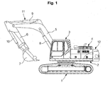
- the present invention relates to an upper frame structure for supporting a cab of construction machinery, which can disperse and offset a load transferred to the cab due to a rollover of the heavy construction machinery and so on.
- the present invention relates to an upper frame structure for supporting a cab of construction machinery, which can support the cap mounted on the upper frame when a vertical load, which is so much that the cab structure is plastically deformed, is applied to the upper frame.
- a conventional upper frame structure for supporting a cap of construction machinery includes a bottom plate 13a having a bottom surface on which a swing ring gear (not illustrated) is mounted; a center frame 13 vertically fixed to the bottom place 13a by welding, and including a pair of side plates 13b on which the working device 11 composed of the boom 5 and so on is installed; a right side frame 14 which is mounted on the right side of the center frame 13, and on which a fuel tank, a hydraulic tank, a main control valve (MCV), and so forth, are installed; and a left side frame 15 which is mounted on the left side of the center frame, and on which the cap 3 is mounted.
- MCV main control valve
- the left side frame 15 may further include a front reinforcement member 15a, a center reinforcement member 15b, and a rear reinforcement member 15c, on which the cap 3 is mounted.
- the reinforcement member of the left side frame 15, on which the cap 3 is mounted is fixed by welding to the side plate 13b of the center frame 13 only. That is, side surfaces of the center reinforcement member 15b and the rear reinforcement member 15c of the left side frame 15 are fixed by welding to a side surface of the side plate 13b of the center frame 13 (indicated as "B" and "D" in the drawings).
- an object of the present invention is to provide an upper frame structure for supporting a cab of construction machinery, which can secure the stability of the construction machinery by supporting the cap mounted on the upper frame when a vertical shock, which is so much that the cab structure is plastically deformed, is applied to the upper frame.
- welding and bolt fastening are selectively adopted to improve the workability and to rectify the structural vulnerability of a structure manufactured only by welding.
- the fastening member may be fixed to form a gap between a bottom surface of the bottom plate and a head part of the fastening member.
- the fastening member may be installed at an edge of the bottom plate.
- a screw hole may be formed on the reinforcement member so that a screw part of the fastening member is fastened into the screw hole.
- a nut member may be fixed by welding to a bottom surface of the reinforcement member so that the screw part of the fastening member is fastened into the nut member.
- At least one fastening member may be installed at an edge of the bottom plate.
- a washer may be integratedly formed on the head part of the fastening member.
- an upper frame structure for supporting a cab of construction machinery includes a center frame having a bottom plate on which a swing ring gear is mounted and a pair of side plates which are vertically fixed to the bottom plate and on which operation devices are mounted; and a left frame mounted on a left side of the center frame and having a left side frame on which the cab is mounted.
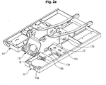
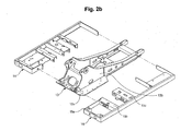
- the upper frame structure also includes reinforcement members A (15b and 15c) each of which has one end fixed by welding to a side surface of the side plate 13b of the center frame 13 and the other end fixed by welding to a side surface of the left side frame 15, and on which the cap 3 is mounted; and a fastening member 16 installed on the bottom plate 13a to offset a load vertically applied to the cab 3 and a load laterally applied to the cab 3, and fixing the reinforcement member 15c to the bottom plate 13a.
- the fastening member 16 may be installed at an edge of the bottom plate 13a.
- a fastening hole 17, which is in the form of an elongated hole or a hole and into which the fastening member 16 is fastened, may be formed on the bottom plate 13a.
- a screw hole (not illustrated) may be formed on the reinforcement member 15c so that a screw part of the fastening member 16 is fastened into the screw hole.
- a nut member 18 on which a screw hole 18a is formed (e.g., a cylindrical boss on which a screw hole is formed) may be fixed by welding to a bottom surface of the reinforcement member 15c so that the screw part of the fastening member 16 is fastened into the screw hole.
- the reinforcement member A may be selectively installed in the center (i.e., on the center reinforcement member 15b) or in the rear (i.e., on the rear reinforcement member 15c) of the left side frame 15.
- the reinforcement member A may be installed in the center and in the rear (corresponding to the center and rear reinforcement members 15b and 15c) of the left side frame 15.
- At least one fastening member 16 may be installed at an edge of the bottom plate 13a (e.g., one fastening member 16 is installed).
- a washer 16b may be integratedly formed on the head part 16a of the fastening member 16.
- the fastening member 16 is fixed to the rear reinforcement member 15c which is fixed by welding to the side plate 13b (indicated as "D” in FIG. 4) and is located in the rear of the left side frame 15, it is also possible that the fastening member (not illustrated) is fixed to the center reinforcement member 15b which is fixed by welding to the side plate 13b (indicated as "B" in FIG. 4) and is located in the center of the left side frame 15.
- the side surface (indicated as "D" in the drawing) of the reinforcement member A (e.g., the rear reinforcement member 15c), which is in close contact with an outer side surface of the side plate 13b of the center frame 13, is fixed by welding to the side plate 13b.
- the fastening member 16 is inserted into the elongated fastening hole 17 that is formed at an end of the bottom plate 13a of the center frame 13, and then the screw part of the fastening member 16 is fastened into the screw hole 18a of the nut member 18 that is fixed by welding to the bottom surface of the reinforcement member 15c. In this case, the fastening member 16 is fastened so as to secure a gap between its head part 16a and the bottom surface of the bottom plate 13a.
- the cab 3 mounted on the left side frame 15 can be supported by the reinforcement member 15c the side surface of which is fixed by welding to the side plate 13b of the center frame 13 (indicated as "D").
- the reinforcement member 15d is fixed to the bottom plate 13a by the fastening member 16 installed at an edge of the bottom plate 13a of the center frame 13, the shear force generated due to the moment that occurs at the welded portion D of the side plate 13b and the reinforcement member 15c when the load is applied to the edge part of the left side frame (indicated by an arrow C) can be minimized.
- the head part 16a of the fastening member 16 becomes in contact with the bottom surface of the bottom plate 13a, and thus the load is offset. Accordingly, the shear force generated due to the moment that occurs at the welded portion D of the side plate 13b and the reinforcement member 15c is minimized, and thus the strength at the welded portion D can be reinforced.
- the cap can be supported on the upper frame by the fixing force obtained by the welding of the side plate 13b of the center frame 13 to the side surface of the reinforcement member 15c (indicated as "D" in the drawing) and the fastening member 16 for fixing the reinforcement member 15c to the bottom plate 13a of the center frame 13.
- the upper frame structure for supporting a cab of construction machinery has the following advantages.
- the upper frame structure can secure the stability of the construction machinery by minimizing the plastic deformation of the cab mounted on the upper frame when a vertical shock, which is so much that the cab structure is plastically deformed, is applied to the upper frame.
- the upper frame structure selectively adopts the welding and the bolt fastening, and thus the structural vulnerability of a structure manufactured only by welding can be rectified with the working efficiency improved.
Landscapes
- Engineering & Computer Science (AREA)
- Mining & Mineral Resources (AREA)
- Civil Engineering (AREA)
- General Engineering & Computer Science (AREA)
- Structural Engineering (AREA)
- Body Structure For Vehicles (AREA)
Applications Claiming Priority (1)
| Application Number | Priority Date | Filing Date | Title |
|---|---|---|---|
| KR1020060092343A KR100753991B1 (ko) | 2006-09-22 | 2006-09-22 | 건설기계의 운전실 캡을 지지하는 상부 프레임 구조 |
Publications (2)
| Publication Number | Publication Date |
|---|---|
| EP1903152A2 true EP1903152A2 (fr) | 2008-03-26 |
| EP1903152A3 EP1903152A3 (fr) | 2014-06-18 |
Family
ID=38615933
Family Applications (1)
| Application Number | Title | Priority Date | Filing Date |
|---|---|---|---|
| EP07012140.5A Withdrawn EP1903152A3 (fr) | 2006-09-22 | 2007-06-21 | Structure de cadre supérieur pour le support de la cabine pour machines de construction |
Country Status (5)
| Country | Link |
|---|---|
| US (1) | US7445272B2 (fr) |
| EP (1) | EP1903152A3 (fr) |
| JP (1) | JP4987644B2 (fr) |
| KR (1) | KR100753991B1 (fr) |
| CN (1) | CN101148896B (fr) |
Cited By (4)
| Publication number | Priority date | Publication date | Assignee | Title |
|---|---|---|---|---|
| EP2551412A1 (fr) * | 2011-07-27 | 2013-01-30 | Liebherr-Hydraulikbagger GmbH | Élément de scène à plateau tournant pour un engin |
| EP2937468A3 (fr) * | 2014-04-22 | 2015-11-04 | Hitachi Construction Machinery Co., Ltd. | Unité de traitement de gaz d'echappement pour une machine de construction |
| RU2598660C2 (ru) * | 2011-12-01 | 2016-09-27 | Либхерр-Хидрауликбаггер Гмбх | Рабочий агрегат со стрелой |
| CN112496616A (zh) * | 2020-11-20 | 2021-03-16 | 薛月飞 | 一种自动化汽车防撞梁焊接熔孔设备 |
Families Citing this family (21)
| Publication number | Priority date | Publication date | Assignee | Title |
|---|---|---|---|---|
| US20080011877A1 (en) * | 2006-05-11 | 2008-01-17 | United Equipment Sales, Inc. | Drywall spraying assembly |
| WO2008147410A1 (fr) * | 2007-05-26 | 2008-12-04 | Koss Michael J | Structure de renforcement de rattrapage pour interface d'élévateur de cabines rops |
| JP4740290B2 (ja) * | 2008-06-27 | 2011-08-03 | 日立建機株式会社 | 建設機械 |
| GB0815344D0 (en) * | 2008-08-22 | 2008-10-01 | Chem Europ Bv Ag | Agriculture application machine |
| JP5077330B2 (ja) * | 2009-11-09 | 2012-11-21 | コベルコ建機株式会社 | 建設機械のアッパーフレーム |
| DE102010015163A1 (de) * | 2010-04-16 | 2011-10-20 | Liebherr-Hydraulikbagger Gmbh | Baumaschine oder Umschlaggerät |
| CN103003497A (zh) * | 2010-08-26 | 2013-03-27 | 日立建机株式会社 | 工程机械 |
| JP2013087455A (ja) * | 2011-10-14 | 2013-05-13 | Kobelco Contstruction Machinery Ltd | 作業機械 |
| JP5582167B2 (ja) * | 2012-05-18 | 2014-09-03 | コベルコ建機株式会社 | 建設機械 |
| JP2014105499A (ja) * | 2012-11-28 | 2014-06-09 | Kobelco Contstruction Machinery Ltd | 建設機械のアッパーフレーム |
| JP6012043B2 (ja) * | 2013-04-26 | 2016-10-25 | キャタピラー エス エー アール エル | 旋回フレームおよび作業機械 |
| JP6174969B2 (ja) * | 2013-10-29 | 2017-08-02 | キャタピラー エス エー アール エル | 建設機械のキャブ支持構造 |
| JP6260284B2 (ja) * | 2014-01-09 | 2018-01-17 | コベルコ建機株式会社 | 建設機械のサイドフレーム |
| JP6262118B2 (ja) * | 2014-10-17 | 2018-01-17 | キャタピラー エス エー アール エル | 建設機械の旋回フレーム |
| JP6392167B2 (ja) * | 2015-05-14 | 2018-09-19 | 株式会社クボタ | フロントローダ |
| JP6654788B2 (ja) * | 2016-07-15 | 2020-02-26 | キャタピラー エス エー アール エル | 建設機械におけるエンジン支持方法およびエンジン支持構造 |
| JP6687979B2 (ja) * | 2016-07-15 | 2020-04-28 | キャタピラー エス エー アール エル | 建設機械におけるエンジン支持構造 |
| JP6588419B2 (ja) * | 2016-12-20 | 2019-10-09 | 日立建機株式会社 | 分解型作業機械 |
| KR102644709B1 (ko) * | 2017-02-28 | 2024-03-06 | 에이치디현대인프라코어 주식회사 | 건설기계의 캐빈 조립체 |
| JP6712671B2 (ja) * | 2019-09-12 | 2020-06-24 | 日立建機株式会社 | 分解型作業機械 |
| US11555289B2 (en) * | 2020-06-30 | 2023-01-17 | Caterpillar Inc. | Construction vehicle |
Family Cites Families (19)
| Publication number | Priority date | Publication date | Assignee | Title |
|---|---|---|---|---|
| JPH07150589A (ja) * | 1993-11-26 | 1995-06-13 | Hitachi Constr Mach Co Ltd | 作業機 |
| JPH10204924A (ja) | 1997-01-20 | 1998-08-04 | Hitachi Constr Mach Co Ltd | 運転室付き作業機 |
| JP2001040706A (ja) * | 1999-08-03 | 2001-02-13 | Komatsu Ltd | 建設機械の旋回台 |
| JP3671790B2 (ja) | 2000-01-13 | 2005-07-13 | 日立建機株式会社 | 建設機械の運転室支持装置 |
| JP2001317084A (ja) * | 2000-05-02 | 2001-11-16 | Hitachi Constr Mach Co Ltd | 建設機械の旋回フレームおよびその組立方法 |
| JP4150486B2 (ja) * | 2000-05-18 | 2008-09-17 | 日立建機株式会社 | 建設機械の旋回フレーム |
| JP3634723B2 (ja) * | 2000-05-31 | 2005-03-30 | 日立建機株式会社 | 建設機械の旋回フレーム |
| JP2002061226A (ja) * | 2000-08-14 | 2002-02-28 | Hitachi Constr Mach Co Ltd | 建設機械の旋回フレーム |
| JP2003082705A (ja) * | 2001-09-10 | 2003-03-19 | Hitachi Constr Mach Co Ltd | 建設機械の旋回フレームおよびその製造方法 |
| JP4429595B2 (ja) * | 2002-12-11 | 2010-03-10 | 株式会社小松製作所 | キャブ支持構造 |
| GB2418661B (en) * | 2003-07-01 | 2007-01-17 | Komatsu Mfg Co Ltd | Construction machine and projecting member thereof` |
| JP2005023718A (ja) * | 2003-07-01 | 2005-01-27 | Komatsu Ltd | 建設機械 |
| SE526115C2 (sv) * | 2003-08-25 | 2005-07-05 | Volvo Constr Equip Holding Se | Anordning vid en hytt hos ett fordon |
| KR100678649B1 (ko) * | 2004-10-06 | 2007-02-06 | 볼보 컨스트럭션 이키프먼트 홀딩 스웨덴 에이비 | 중장비 운전실의 하중지지장치 및 그 제작방법 |
| KR100702179B1 (ko) * | 2005-05-06 | 2007-04-02 | 볼보 컨스트럭션 이키프먼트 홀딩 스웨덴 에이비 | 중장비 운전실 보호구조 |
| KR100689292B1 (ko) * | 2005-06-01 | 2007-03-02 | 볼보 컨스트럭션 이키프먼트 홀딩 스웨덴 에이비 | 중장비 운전실에 장착되는 운전자 보호구조물 |
| KR100689293B1 (ko) * | 2005-07-25 | 2007-03-02 | 볼보 컨스트럭션 이키프먼트 홀딩 스웨덴 에이비 | 건설기계의 운전실 캡을 지지하는 상부프레임 구조 |
| JP4655815B2 (ja) * | 2005-08-12 | 2011-03-23 | コベルコ建機株式会社 | 建設機械のキャビン |
| JP2007106286A (ja) * | 2005-10-14 | 2007-04-26 | Kobelco Contstruction Machinery Ltd | 作業機械のキャブ |
-
2006
- 2006-09-22 KR KR1020060092343A patent/KR100753991B1/ko not_active Expired - Fee Related
-
2007
- 2007-06-20 US US11/820,665 patent/US7445272B2/en not_active Expired - Fee Related
- 2007-06-21 EP EP07012140.5A patent/EP1903152A3/fr not_active Withdrawn
- 2007-07-09 CN CN2007101286326A patent/CN101148896B/zh not_active Expired - Fee Related
- 2007-09-12 JP JP2007236960A patent/JP4987644B2/ja not_active Expired - Fee Related
Cited By (4)
| Publication number | Priority date | Publication date | Assignee | Title |
|---|---|---|---|---|
| EP2551412A1 (fr) * | 2011-07-27 | 2013-01-30 | Liebherr-Hydraulikbagger GmbH | Élément de scène à plateau tournant pour un engin |
| RU2598660C2 (ru) * | 2011-12-01 | 2016-09-27 | Либхерр-Хидрауликбаггер Гмбх | Рабочий агрегат со стрелой |
| EP2937468A3 (fr) * | 2014-04-22 | 2015-11-04 | Hitachi Construction Machinery Co., Ltd. | Unité de traitement de gaz d'echappement pour une machine de construction |
| CN112496616A (zh) * | 2020-11-20 | 2021-03-16 | 薛月飞 | 一种自动化汽车防撞梁焊接熔孔设备 |
Also Published As
| Publication number | Publication date |
|---|---|
| US7445272B2 (en) | 2008-11-04 |
| CN101148896A (zh) | 2008-03-26 |
| CN101148896B (zh) | 2011-11-16 |
| KR100753991B1 (ko) | 2007-08-31 |
| JP4987644B2 (ja) | 2012-07-25 |
| JP2008075445A (ja) | 2008-04-03 |
| EP1903152A3 (fr) | 2014-06-18 |
| US20080073938A1 (en) | 2008-03-27 |
Similar Documents
| Publication | Publication Date | Title |
|---|---|---|
| US7445272B2 (en) | Upper frame structure for supporting cab of construction machinery | |
| EP1748113B1 (fr) | Engin de travaux publics avec une structure du chassis supérieure pour le support d'une cabine | |
| WO2016139226A1 (fr) | Dispositif de déplacement de contrepoids | |
| US20100300778A1 (en) | Structure for Attaching Rear Work Machine to Tractor | |
| JP4655815B2 (ja) | 建設機械のキャビン | |
| JP2010255215A (ja) | 建設機械におけるキャブ用の補強材 | |
| EP2151527A2 (fr) | Structure renforcée pour la cabine d'une machine de travail | |
| JP5996122B2 (ja) | 作業車両のキャブ及びその製造方法 | |
| US7959219B2 (en) | Reinforcement structure for pipe and cab structure for construction machine having the same | |
| EP2011926A1 (fr) | Cadre supérieur pour excavateur | |
| US8960778B2 (en) | Revolving frame of construction machine | |
| CN1980827B (zh) | 建筑机械的驾驶室 | |
| JP2001173017A (ja) | 建設機械 | |
| JP2011105032A (ja) | 作業機械のキャブ構造 | |
| JP2007063839A (ja) | 建設機械用保護構造物及び建設機械用キャブ | |
| JP2008201328A (ja) | トラクタの後作業機装着フレーム構造。 | |
| KR20080093582A (ko) | 빔형상의 보강부재가 구비된 굴삭기의 상부프레임 | |
| WO2005003468A1 (fr) | Engin de terrassement et son bras articule | |
| KR101425070B1 (ko) | 유압 절단기 | |
| WO2010122696A1 (fr) | Structure de protection de cabine pour machine de construction | |
| JP4920570B2 (ja) | 建設機械におけるキャブ補強構造 | |
| JP2024118909A (ja) | 建設機械の旋回フレーム | |
| WO2017168784A1 (fr) | Engin de chantier | |
| CN205589165U (zh) | 底护板及包括该底护板的车辆 |
Legal Events
| Date | Code | Title | Description |
|---|---|---|---|
| PUAI | Public reference made under article 153(3) epc to a published international application that has entered the european phase |
Free format text: ORIGINAL CODE: 0009012 |
|
| AK | Designated contracting states |
Kind code of ref document: A2 Designated state(s): AT BE BG CH CY CZ DE DK EE ES FI FR GB GR HU IE IS IT LI LT LU LV MC MT NL PL PT RO SE SI SK TR |
|
| AX | Request for extension of the european patent |
Extension state: AL BA HR MK YU |
|
| PUAL | Search report despatched |
Free format text: ORIGINAL CODE: 0009013 |
|
| AK | Designated contracting states |
Kind code of ref document: A3 Designated state(s): AT BE BG CH CY CZ DE DK EE ES FI FR GB GR HU IE IS IT LI LT LU LV MC MT NL PL PT RO SE SI SK TR |
|
| AX | Request for extension of the european patent |
Extension state: AL BA HR MK RS |
|
| RIC1 | Information provided on ipc code assigned before grant |
Ipc: E02F 9/08 20060101AFI20140515BHEP Ipc: E02F 9/12 20060101ALI20140515BHEP |
|
| 17P | Request for examination filed |
Effective date: 20141217 |
|
| AKX | Designation fees paid |
Designated state(s): DE FR GB IT |
|
| AXX | Extension fees paid |
Extension state: HR Extension state: RS Extension state: AL Extension state: MK Extension state: BA |
|
| STAA | Information on the status of an ep patent application or granted ep patent |
Free format text: STATUS: THE APPLICATION IS DEEMED TO BE WITHDRAWN |
|
| 18D | Application deemed to be withdrawn |
Effective date: 20180103 |