EP1903155B1 - Cadres d'espace et agencement de noeud de connexion pour ceux-ci - Google Patents
Cadres d'espace et agencement de noeud de connexion pour ceux-ci Download PDFInfo
- Publication number
- EP1903155B1 EP1903155B1 EP07252968A EP07252968A EP1903155B1 EP 1903155 B1 EP1903155 B1 EP 1903155B1 EP 07252968 A EP07252968 A EP 07252968A EP 07252968 A EP07252968 A EP 07252968A EP 1903155 B1 EP1903155 B1 EP 1903155B1
- Authority
- EP
- European Patent Office
- Prior art keywords
- frame
- members
- chord
- major
- node
- Prior art date
- Legal status (The legal status is an assumption and is not a legal conclusion. Google has not performed a legal analysis and makes no representation as to the accuracy of the status listed.)
- Not-in-force
Links
Images







Classifications
-
- E—FIXED CONSTRUCTIONS
- E04—BUILDING
- E04B—GENERAL BUILDING CONSTRUCTIONS; WALLS, e.g. PARTITIONS; ROOFS; FLOORS; CEILINGS; INSULATION OR OTHER PROTECTION OF BUILDINGS
- E04B1/00—Constructions in general; Structures which are not restricted either to walls, e.g. partitions, or floors or ceilings or roofs
- E04B1/18—Structures comprising elongated load-supporting parts, e.g. columns, girders, skeletons
- E04B1/19—Three-dimensional [3D] framework structures
-
- E—FIXED CONSTRUCTIONS
- E04—BUILDING
- E04H—BUILDINGS OR LIKE STRUCTURES FOR PARTICULAR PURPOSES; SWIMMING OR SPLASH BATHS OR POOLS; MASTS; FENCING; TENTS OR CANOPIES, IN GENERAL
- E04H12/00—Towers; Masts or poles; Chimney stacks; Water-towers; Methods of erecting such structures
-
- F—MECHANICAL ENGINEERING; LIGHTING; HEATING; WEAPONS; BLASTING
- F24—HEATING; RANGES; VENTILATING
- F24S—SOLAR HEAT COLLECTORS; SOLAR HEAT SYSTEMS
- F24S25/00—Arrangement of stationary mountings or supports for solar heat collector modules
-
- H—ELECTRICITY
- H01—ELECTRIC ELEMENTS
- H01Q—ANTENNAS, i.e. RADIO AERIALS
- H01Q15/00—Devices for reflection, refraction, diffraction or polarisation of waves radiated from an antenna, e.g. quasi-optical devices
- H01Q15/14—Reflecting surfaces; Equivalent structures
- H01Q15/18—Reflecting surfaces; Equivalent structures comprising plurality of mutually inclined plane surfaces, e.g. corner reflector
-
- E—FIXED CONSTRUCTIONS
- E04—BUILDING
- E04B—GENERAL BUILDING CONSTRUCTIONS; WALLS, e.g. PARTITIONS; ROOFS; FLOORS; CEILINGS; INSULATION OR OTHER PROTECTION OF BUILDINGS
- E04B1/00—Constructions in general; Structures which are not restricted either to walls, e.g. partitions, or floors or ceilings or roofs
- E04B1/18—Structures comprising elongated load-supporting parts, e.g. columns, girders, skeletons
- E04B1/19—Three-dimensional [3D] framework structures
- E04B1/1903—Connecting nodes specially adapted therefor
-
- E—FIXED CONSTRUCTIONS
- E04—BUILDING
- E04B—GENERAL BUILDING CONSTRUCTIONS; WALLS, e.g. PARTITIONS; ROOFS; FLOORS; CEILINGS; INSULATION OR OTHER PROTECTION OF BUILDINGS
- E04B1/00—Constructions in general; Structures which are not restricted either to walls, e.g. partitions, or floors or ceilings or roofs
- E04B1/18—Structures comprising elongated load-supporting parts, e.g. columns, girders, skeletons
- E04B1/19—Three-dimensional [3D] framework structures
- E04B2001/1924—Struts specially adapted therefor
- E04B2001/1933—Struts specially adapted therefor of polygonal, e.g. square, cross section
-
- E—FIXED CONSTRUCTIONS
- E04—BUILDING
- E04B—GENERAL BUILDING CONSTRUCTIONS; WALLS, e.g. PARTITIONS; ROOFS; FLOORS; CEILINGS; INSULATION OR OTHER PROTECTION OF BUILDINGS
- E04B1/00—Constructions in general; Structures which are not restricted either to walls, e.g. partitions, or floors or ceilings or roofs
- E04B1/18—Structures comprising elongated load-supporting parts, e.g. columns, girders, skeletons
- E04B1/19—Three-dimensional [3D] framework structures
- E04B2001/1924—Struts specially adapted therefor
- E04B2001/1936—Winged profiles, e.g. with a L-, T-, U- or X-shaped cross section
-
- E—FIXED CONSTRUCTIONS
- E04—BUILDING
- E04B—GENERAL BUILDING CONSTRUCTIONS; WALLS, e.g. PARTITIONS; ROOFS; FLOORS; CEILINGS; INSULATION OR OTHER PROTECTION OF BUILDINGS
- E04B1/00—Constructions in general; Structures which are not restricted either to walls, e.g. partitions, or floors or ceilings or roofs
- E04B1/18—Structures comprising elongated load-supporting parts, e.g. columns, girders, skeletons
- E04B1/19—Three-dimensional [3D] framework structures
- E04B2001/1975—Frameworks where the struts are directly connected to each other, i.e. without interposed connecting nodes or plates
-
- E—FIXED CONSTRUCTIONS
- E04—BUILDING
- E04B—GENERAL BUILDING CONSTRUCTIONS; WALLS, e.g. PARTITIONS; ROOFS; FLOORS; CEILINGS; INSULATION OR OTHER PROTECTION OF BUILDINGS
- E04B1/00—Constructions in general; Structures which are not restricted either to walls, e.g. partitions, or floors or ceilings or roofs
- E04B1/18—Structures comprising elongated load-supporting parts, e.g. columns, girders, skeletons
- E04B1/19—Three-dimensional [3D] framework structures
- E04B2001/1981—Three-dimensional [3D] framework structures characterised by the grid type of the outer planes of the framework
- E04B2001/1984—Three-dimensional [3D] framework structures characterised by the grid type of the outer planes of the framework rectangular, e.g. square, grid
-
- E—FIXED CONSTRUCTIONS
- E04—BUILDING
- E04B—GENERAL BUILDING CONSTRUCTIONS; WALLS, e.g. PARTITIONS; ROOFS; FLOORS; CEILINGS; INSULATION OR OTHER PROTECTION OF BUILDINGS
- E04B1/00—Constructions in general; Structures which are not restricted either to walls, e.g. partitions, or floors or ceilings or roofs
- E04B1/18—Structures comprising elongated load-supporting parts, e.g. columns, girders, skeletons
- E04B1/19—Three-dimensional [3D] framework structures
- E04B2001/199—Details of roofs, floors or walls supported by the framework
-
- E—FIXED CONSTRUCTIONS
- E04—BUILDING
- E04C—STRUCTURAL ELEMENTS; BUILDING MATERIALS
- E04C3/00—Structural elongated elements designed for load-supporting
- E04C3/02—Joists; Girders, trusses, or trusslike structures, e.g. prefabricated; Lintels; Transoms; Braces
- E04C3/04—Joists; Girders, trusses, or trusslike structures, e.g. prefabricated; Lintels; Transoms; Braces of metal
- E04C2003/0486—Truss like structures composed of separate truss elements
- E04C2003/0495—Truss like structures composed of separate truss elements the truss elements being located in several non-parallel surfaces
-
- F—MECHANICAL ENGINEERING; LIGHTING; HEATING; WEAPONS; BLASTING
- F24—HEATING; RANGES; VENTILATING
- F24S—SOLAR HEAT COLLECTORS; SOLAR HEAT SYSTEMS
- F24S25/00—Arrangement of stationary mountings or supports for solar heat collector modules
- F24S25/10—Arrangement of stationary mountings or supports for solar heat collector modules extending in directions away from a supporting surface
- F24S25/13—Profile arrangements, e.g. trusses
-
- Y—GENERAL TAGGING OF NEW TECHNOLOGICAL DEVELOPMENTS; GENERAL TAGGING OF CROSS-SECTIONAL TECHNOLOGIES SPANNING OVER SEVERAL SECTIONS OF THE IPC; TECHNICAL SUBJECTS COVERED BY FORMER USPC CROSS-REFERENCE ART COLLECTIONS [XRACs] AND DIGESTS
- Y02—TECHNOLOGIES OR APPLICATIONS FOR MITIGATION OR ADAPTATION AGAINST CLIMATE CHANGE
- Y02E—REDUCTION OF GREENHOUSE GAS [GHG] EMISSIONS, RELATED TO ENERGY GENERATION, TRANSMISSION OR DISTRIBUTION
- Y02E10/00—Energy generation through renewable energy sources
- Y02E10/40—Solar thermal energy, e.g. solar towers
- Y02E10/47—Mountings or tracking
Definitions
- This invention pertains to support armatures. More particularly, it pertains to other-than-shell space frames and to connection node arrangements and other structural elements for such frames.
- a space frame is a network of structural framing members, such as tubes, interconnected at multi-member connection points (commonly called "nodes") in such a way that the whole structure behaves as one structural element.
- nodes multi-member connection points
- structural elements often act independently of each other and can have completely separate force paths.
- a single layer grid is a network (arranged on a triangular, rectangular or other geometric scheme) of node structures and structural members of desired cross-sections and sizes.
- a single layer grid achieves its structural strength by locating the grid elements in a curved surface.
- single layer grids are most commonly used to define domes, vaults, and other constructions having simple or compound curvature.
- Double layer grids are space frames in which the nodes are located in two separate surfaces which commonly are flat and in parallel spaced relation to each other; vaulted DLGs having curved parallel spaced surfaces also are known.
- the nodes are interconnected in each surface by straight structural elements called chords; the chords in each surface are arranged in repeating geometric patterns which usually are squares, but triangles and rectangles also can be defined by the chord array in each surface.
- the squares (or other geometric shapes) defined by the chords in the principal surfaces of a DLG normally are of the same size throughout the structures.
- the two surfaces of a DLG are interconnected by further straight structural elements which are referred to herein as struts to distinguish them from the chord elements which lie in the principal surfaces of a DLG.
- the nodes in a top surface of a DLG are located so that the centroid of the area of the square, e.g., they define is located over a node in the bottom surface of the DLG, and struts are connected from each of those top surface nodes to that bottom surface node.
- the struts in a DLG which extend between the principal surfaces of the DLG are oblique to the principal surfaces.
- Space frames are routinely used as static structures, i.e., structures which are mounted on and supported by fixed supports or foundations.
- DLG structures which are square or rectangular in overall plan view (i.e., as seen from a vantage point on a line perpendicular to the DLG's principal surfaces) can be supported at the ends of the structure or at the mid-length, e.g., of the structure.
- space frames it is known to use space frames as movable covers over sports arenas and stadiums, in which case the space frame supports are carried on roller or trolley units which are movable along horizontal tracks; space frames used in such situations are fundamentally static structures because the movement of such a space frame does not significantly alter the frame loads due to gravity.
- a movable support armature suitable for supporting reflectors of electromagnetic radiation which is defined substantially as a double layer grid space frame of overall rectangular cubical shape having parallel flat major surfaces, the armature comprising plural parallel major chord framing member each having an elongate axis and disposed essentially in respective ones of the flat frame major surfaces and extending parallel to one of the two elongate extents of the frame, the armature also comprising node connector structures disposed at spaced locations along each major chord member, minor chord members connected between corresponding nodes on major chord members defining the flat major frame surfaces aforesaid to define an array of major and minor chord members in each major frame surface, and strut framing members interconnected between nodes in different ones of the major frame surfaces; reflectors supported by the frame are located within the frame on supports in respective openings framed by the major and minor chord members in a top one of the flat frame major surfaces.
- connections of framing members to nodes in a single layer grid rarely are anything other than rigid connections defined by bolting, riveting or welding of the associated framing members to each other or to other node elements at a node.
- Such rigid connections of framing members at grid nodes enables the connections to transmit to the nodes, and to other members at the node, moment loads on the framing members; moment loads are loads which act on a framing member in ways which cause the framing member to tend to rotate or pivot relative to the node.
- the connections of the framing members to the nodes rarely are moment connections; they are connections which either are true pinned connections or are connections which are modeled as pinned connections.
- a true pinned connection of a DLG framing member at a node is a simple connection to define and to make. Such a connection typically is made by passing a bolt or a pin through aligned holes in a framing member and in a node connector arrangement to which that framing member and other framing members are pinned. To the extent that strut axes do not intersect the axes of the chords at the node (or the axis of a major chord at the node), the node is said to have eccentricity. Eccentricity at a DLG node causes the node to have moment loads or other undesired loads applied to it.
- the present invention is as claimed in claim 1. Particular embodiments of the present invention are as claimed in clams 2-13.
- the invention beneficially addresses the needs identified above. It does so by providing structural arrangements and procedures which are described in detail below, along with descriptions of the several benefits and advantages of those structures and procedures. Principal aspects of the invention are summarized next below.
- One form of space frame according to this invention is a rotatably movable support armature for a curved reflector of electromagnetic radiation, notably solar radiation.
- the armature is defined substantially as a double layer grid space frame having nonparallel major surfaces.
- the armature is comprised by plural parallel major chord framing members each of which has an elongate axis and is disposed in a frame major surface. Each major chord member extends parallel to an elongate extent of the frame.
- the major chord members include only a pair of bottom major chord members essentially in a bottom one of the frame major surfaces, an only three upper major chord members.
- the upper major chord members include a central chord member which is located between two outer chord members.
- the outer chord members lie in respective ones of two planes which also include the center chord member.
- the planes intersect at the center chord member at an oblique included angle which is concave away from the frame bottom plane.
- Node connector structures are disposed at spaced locations along each major chord member.
- Minor chord members are connected between corresponding nodes on the major chord members defining the respective planes described above to define, for example, rectangular arrays of major and minor chord members in each plane.
- Strut framing members are interconnected between nodes in different ones of the planes. Bracing framing members may be connected between diagonally opposite nodes in each array.
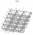
- FIG. 1 is a perspective view of a double layer grid (DLG) space frame of prior art, which has indeterminate length and which has constant square bay spacing;
- DLG double layer grid
- FIG. 2 is a perspective of a simple DLG space frame not according to the present invention, in the nature of a triangular truss, which has variable bay spacing;
- FIG. 3 is a perspective view of a node connector not according to the present invention for the space frame shown in FIG. 2 ;
- FIG. 4 is a fragmentary end elevation view of the node connector of FIG. 3 with connections of framing members to it in the construction of the space frame shown in FIG. 2 ;
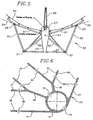
- FIG. 5 is an end elevation view of a more complex DLG space frame in accordance with the invention which is a movable support armature for a curved mirror and is useful in a solar power generation installation;
- FIG. 6 is an end view of a first node connector configuration useful in the DLG shown in FIG. 5 ;
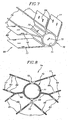
- FIG. 7 is a perspective view of the node connector of FIG. 6 ;
- FIG. 8 is an end view of a second node connector configuration useful in the DLG shown in FIG. 5 ;
- FIG. 9 is a perspective view of the node connector of FIG. 8 ;
- FIG. 10 is an end view of a third node connector configuration useful in the DLG shown in FIG. 5 ;
- FIG. 11 is an elevation view of a shear pin useful in making connections of space frame framing members to node connectors in the practice of aspects of this invention
- FIG. 12 is a plan view of a known style of clip retainer useful with the shear pin of FIG. 11 ;
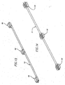
- FIG. 13 is a perspective view illustrating a first step in the construction of the DLG in accordance with the invention of FIG. 5 ;
- FIG. 14 is a perspective view illustrating a second step in that same construction process
- FIG. 15 is a perspective view illustrating a third step in that same construction process
- FIG. 16 is a perspective view illustrating a fourth step in that same construction process
- FIG. 17 is a perspective view illustrating a fifth step in that same construction process.
- FIG. 18 is a perspective view illustrating a sixth step in that same construction process.
- FiG. 19 is a perspective view illustrating a seventh step in that same construction process.
- FIG. 20 is a perspective view illustrating an eighth step in that same construction process.
- FIG. 21 is a perspective view illustrating a ninth step in that same construction process.
- FIG. 22 is a perspective view illustrating a tenth step in that same construction process, substantial parts of the previously assembled space frame being deleted from FIG. 22 for enhanced clarity of depiction of structure being added by step ten;
- FIG. 23 is a top plan view which illustrates an eleventh step in that same construction process
- FIG. 24 is a fragmentary end elevation view of a portion of the structure shown in FIG. 23 ;
- FIG. 25 is a perspective view of one the two pivot (torque transfer) arms which are components of the mirror support armature in accordance with the invention of FIG. 5 ;
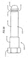
- FIG. 26 is an elevation view of another shear pin useful in the practice of aspects of this invention.
- FIG. 1 is a perspective view of a portion of a rectilinearly subdivided DLG space frame 10.
- Frame 10 is composed of framing members which are disposed to define top 11 and bottom 12 layers of the frame and to interconnect those layers in an arrangement which causes frame layers 11 and 12 to be in spaced parallel relation to each other.
- Layers 11 and 12 can also be called grids, hence the name double layer grid (DLG) for the type of space frame shown in FIG. 1 .
- DLG double layer grid
- the framing members of DLG 10 are comprised by chords which are interconnected to define top and bottom layers 11 and 12 of the DLG which has an end 13 and opposite sides 14 and 15.
- the chords which extend along the length of the DLG can be and preferably are continuous (subject to limitations on the lengths available) and for resent purposes, are called major chords.
- DLG 10 includes upper major chords 16 and lower major chords 17.
- the upper and lower major chords are interconnected and spaced by upper 18 and lower 19 transverse minor chords, each of which has a length equal (or essentially so) to the spacing between the major chords which they interconnect.
- the major and minor chords of DLG 10 are aligned to be parallel to respective orthogonal directions, i.e., the length and the width, of the DLG.
- the major and minor chords are interconnected at junction points which are commonly called nodes.
- DLG 10 has upper nodes 20 and lower nodes 21.
- the distance in each layer between adjacent parallel minor chords is equal to the distance between adjacent parallel major chords, and so the upper nodes 20 and the lower nodes 21 are located at the corners of aligned rows and columns of squares bounded by the major and minor chords; each top layer square corresponds to a bay of the DLG; the chords in the bottom layer of frame 10 also define square bays.
- DLG 10 has constant square bay spacing.
- the DLG is described as having constant rectangular bay spacing.
- Chords 16 and 18 of DLG 10 can be said to be in (or to define) a top surface of the DLG; similarly, chords 17 and 19 are in (define) a bottom surface of the DLG.
- the top and bottom surfaces of DLG 10 are parallel.
- the top and bottom layers of DLG 10 are spaced from and supported relative to each other by further diagonal framing members 22 called struts each of which extends between a top layer node 20 and a bottom layer node 21.
- struts each of which extends between a top layer node 20 and a bottom layer node 21.
- the upper major and minor chords are offset relative to the lower major and minor chords in such manner that the lower nodes 21 are located vertically below the centers of the square openings defined by the chords of the upper grid; upper nodes 20 are located vertically above the centers of the openings defined by the chords of the lower grid
- the struts are disposed in planes which are inclined relative to the top and bottom surfaces of frame 10. As shown in FIG.
- struts 22 connected to each upper node 20 and to each lower node 21.
- the struts are disposed in two sets of parallel planes, one set parallel to and intersecting one upper major chord and one lower major chord, and one set parallel to and intersecting one line of upper minor chords and one line of lower minor chords.
- strut planes slope down and inwardly between the top and bottom surfaces of the frame.
- the frame is six squares (bays) wide in its top layer and five squares (bays) wide in its bottom layer, while the length of the frame as depicted is indefinite.
- Such a DLG frame can be described by the notation 6xn/5x(n-1) in which 6xn denotes a top grid 6 bays wide by n bays long, and the notation 5x(n-1) denotes a bottom grid 5 bays wide by (n-1) bays long.
- frame 10 has pertained to geometrical aspects of the frame, to the linear structural framing members which comprise the frame, and to the nodes where the lines (axes) of the different framing members intersect each other in an ideal frame. That description is a background and foundation for the following descriptions of actual frames and of the structures which are employed to interconnect framing members at nodes in those frames. The following descriptions include descriptions of node connector arrangements which enable the design and construction of DLG-type space frames having advanced properties and benefits.
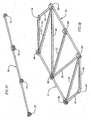
- FIG. 2 is a perspective view of a DLG-type space frame 25 in the form of a truss of inverted equilateral triangular cross-section.
- frame 25 is a 1x8/0x0 DLG frame.
- Frame 25 has two upper major chords 26 and one lower major chord 27, all of which extend along the full length of the frame.
- FIGs. 3 and 4 show a node connector 28 of frame 25. Because the cross-sectional configuration of frame 25 is that of an equilateral triangle, a single basic node connector configuration can be used at all nodes in the frame.
- the framing members of frame 25 preferably are square tubes, the major chords preferably having cross-sections larger than the cross-sections of the other framing members (minor chords, struts, and torsion braces) present in the frame; the other framing members preferably are of the same cross-sectional dimensions.
- the frame material preferably is an extrudible aluminum alloy, and the framing members preferably are extruded aluminum tubes.
- the node connectors 28 preferably are defined by extrusions of the same aluminum alloy.
- FIG. 4 shows the pinned connection of two struts 30 to a node connector 28 which has a pinned connection to lower chord 27; a connection of struts to a node connector on either of the upper major chords would have substantially the same appearance as shown in FIG. 4 except that the upper major chords actually are turned about their longitudinal axes - visualize that FIG. 4 is rotated 120° in either direction.
- Node connector 28 has a chord-receiving base channel portion 31 which has a flat base 32 and two parallel spaced flanges 33 perpendicular to the base.
- the spacing between opposing faces of flanges 33 is slightly greater than the exterior width of a major chord, and the height of the flanges from the base 31 preferably is equal to the height of a major chord.
- Node connector 28 also carries along the exterior of the channel portion, in directions parallel to the length of the connector's channel portion, plural fixed structural elements (flanges or ribs) 34 which define two pairs of parallel spaced opposing and substantially flat surfaces 35 and 36.
- surfaces 35 and surfaces 36 are spaced a distance which is slightly greater than the width of the extrusion from which the struts, minor chords and torsion braces of frame 25 are defined. Further, surfaces 35 are spaced parallel to and equally from opposite sides of a plane 37 which passes through the structural neutral axis of bottom chord 27 as received in and secured in the channel portion 31 of node connector 28 as shown in FIG. 4 . Because chord 27 is defined by an extruded square tube of uniform wall thickness, the location of the neutral axis of the chord is coincident with the centroid of the cross-sectional area of the tubular chord.
- surfaces 36 are spaced parallel to and equally from opposite sides of a plane 38 which passes through the neutral axis of chord 27 as received and secured in node connector 28.
- flanges 34 are parallel to the length of the node connector and have the described geometrical relations to the channel portion of the node connector, the assembled node connection is free of eccentricities regardless of the angularities of the pertinent struts relative to the chord.
- Node connector 28 preferably is doubly pinned to chord 27 by use of shear pins 40 and clip retainers 41 as depicted in FIGs. 11 and 12 .
- Double pinning of the connector to chord 27 provides a rigid connection between them; in a DLG a rigid connection of a node connector to at least one of the framing members engaging that node connector is important
- the connector has two sets of shear pin holes 42 formed through channel portions flanges 33 at spaced locations along the length of the connector. The two holes 42 in each hole set are centered on a line which is normal to the length of the node connector and preferably passes through the neutral axis of the chord 27 as secured in node connector.
- node connectors 28 can be used to make splices between aligned chord member lengths. Splicing is accomplished by making a splicing node connector of extended length, and by doubly pinning the adjacent ends of two chord member lengths to the node connector.
- shear pin holes 43 are formed through node connector flanges 34 for each other framing member which is to be connected to that node connector in completed frame 25.
- each other framing member is simply (singly) pinned to the node connector, one hole 43 per each framing member to be connected to the connector is formed in each relevant flange 34, and the two holes in the coacting flanges are centered on a line which is perpendicular to flange surfaces 35 or 36.
- two aligned shear pin holes are formed through the walls of each other framing member; they are located on a line perpendicular to the length of the framing member and passing, preferably, through the neutral axis of that member.
- upper major chords 26 and lower chord 27 of frame 25 are of equal length; compare the different lengths of major chords 16 and 17 in frame 10 shown in FIG. 1 .
- Upper major chords 26 are located in spaced parallel relation to each other by minor chords 44 which are parallel to each other and perpendicular to the major chords, and so the upper major chords mount (as described above) node connectors 28 at their ends and at opposed locations spaced along their lengths.
- node connectors 28 are fixedly mounted to lower chord 27 at locations between the ends of that chord which are, respectively, midway along the distance between corresponding upper minor chords 44.
- an end node connector 28 is fixedly mounted to each end of lower chord 27.
- each of node connectors 28 located between, rather than at, the ends of lower chord 27, four struts 30 are pinned to each connector; two of those struts have their ends snugly yet movably received between surfaces 35 of the connector so that the opposing flat exterior surfaces of the strut substantially register with surfaces 35, and another two of those struts have their ends snugly yet moveably received between surfaces 36 of the connector so that the opposing flat exterior surfaces of those struts substantially register with surfaces 36.
- the ends of struts 30 are pinned to the connectors 28 with which they cooperate by use of shear pins 40 passed through the strut-end holes and through holes 43 of the connector.
- All shear pins preferably are held in place by connection of clip retainers 41 to the pins; each retainer cooperates with its pin in a circumferential recess (groove) 47 defined in the round pin shank adjacent a distal end of the pin which is opposite from an enlarged head 48 at the other end of the pin.
- Two struts 30 are connected from the node connector at each end of lower chord 27 to a corresponding frame end connector at the adjacent ends of upper major chords 26; see FIG. 2 .
- frame 25 includes a torsion brace framing member 49 in each bay of the frame; a bay of frame 25 is the opening bounded by the upper major chords 26 and two adjacent upper minor chords 44.
- Each torsion brace is connected between the node connectors at the diagonally opposite corners of a bay.
- the torsion braces lie in the plane of the upper minor chords, and so the torsion brace ends are simply (singly) pinned between the same surfaces 35 or 36 of each affected node connector between which an end of an upper minor chord 44 is similarly pinned.
- the torsion braces 49 alternate in the directions in which they are skewed to the length of the frame.
- node connectors 28' and 28" in FIG. 2 are at the opposite ends of a single upper minor chord 44.
- connector 28' has associated with it two struts 30, an upper minor chord 44, and two torsion braces 49. Struts 30 can be received between surfaces 35 of connector 28' and framing members 44 (one) and 49 (two) can be received between surfaces 36 of that connector.
- node connector 28" has associated with it an upper major chord, a minor chord 44, and two struts 30.
- connector 28' has a length greater than that of connector 28" by an amount adequate to accommodate the ends of three framing members between surfaces 36 of connector 28'. That connector length difference is easily handled by making connector 28' from a longer length of the connector extrusion than the length of the extrusion section used to make connector 28", and by drilling three sets of holes 43 through the flanges forming surfaces 35 rather than one set of such holes.
- each shear pin holes formed in each node connector 28 have the same design diameter (and preferably actual diameter) as the diameter of the cylindrical shanks of the shear pins to be inserted into those holes, and that the shear pin holes formed in all framing members of frame 25 also have the same design (also preferably actual) diameter as the shank diameter of the shear pins used to pin them to node connector 28. That is, each shear pin has zero clearance relative to the node connector and framing member holes through which its shank will be inserted to connect the relevant framing member to the relevant node connector. Such zero clearance means, as a practical matter, that each shear pin has an interference fit in each of the holes with which it coats when installed in the frame.
- frame 25 can be built with great precision and has no play or looseness in any of its connections.
- the lack of play or looseness in the framing member connections in a space frame means that each framing member will experience and transmit loads which very closely correspond to design loads, and that all framing members will effectively share and correctly transmit loads and load forces within the frame.
- FIG. 2 An inspection of FIG. 2 will reveal that it has 8 bays along its length, i.e., 8 intervals between 9 spaced upper minor chords 44. Such inspection of FIG. 2 will reveal that the 4 bays in the mid-length of the frame are of the same length, which length is less than the equal lengths of the other 4 bays of the frame.
- frame 25 has variable bay spacing; bay spacing in frame 25 can be defined as the distance along the length of the frame between the centroids of the rectangular areas on opposite sides of a minor chord. Variable bay spacing means that some node connectors are closer to each other along a given major chord than are others of the node connectors along that major chord.
- all of the node connectors along that major chord can be (preferably are) made with the same transverse cross-sectional configuration, i.e., made by use of different pieces cut from a single extrusion.
- Variable bay spacing is possible with node connectors 28 because, in all of the node connectors, the elements of the connectors which define surfaces 35, 36 are arranged to be parallel to the length of the portion of the connector which cooperates with the major chord of the frame which can (preferably does) extend continuously through the connector.
- Variable bay spacing is easily achieved in frame 25 by varying the lengths of struts 30 and of torsion braces 49 as needed.
- the node connectors and framing members of frame 25 be defined of the same material so that they all have the same coefficient of thermal expansion, thereby resulting in a frame which develops minimal stresses in it with temperature change and does not deflect or distort due to temperature changes.
- the preferred material for definition of the node connectors and framing members of frame 25 is an aluminum alloy, and those frame elements preferably are made by extrusion processes. Shear pins used in the connections within the frame can be made of aluminum or of stainless steel.
- the node connectors and framing members of frame 25, or of other frames according to this invention can be made of other materials. If steel is the material of choice, it will be apparent that the node connectors can be fabricated out of discrete components preferably welded together into integral articles of manufacture. Pultruded materials such as fiber reinforced plastics (synthetic resins) can be used; in that connection, pultruded components are regarded as equivalents of extruded components. Both extruded and pultruded components can be used in a given frame according to this invention. Node connectors can be made by other fabrication processes such as casting or machining.
- node connectors in the frame can have the same cross-sectional configuration. If the frame cross-sectional configuration were that of an isosceles triangle, then two different cross-sectional configurations would be needed for the node connectors. Similarly, if the frame configuration were to be that of a triangle having no equal included angles, three different node connector cross-sections would be required.
- the principles used in the design of node connectors 28 can be used in the design of node connectors for DLG-type space frames having other configurations than trusses of triangular cross-section.
- Square-section box trusses can be defined by a variation of node connectors 28 in which the central planes between surfaces 35 and 36 intersect each other at a 90° angle rather than a 60° angle. Moreover, a truss designed and constructed according to this invention can be disposed vertically to serve as a tower. Different node connector cross-sections are readily accommodated in the practice of this invention, as made more clear by the following descriptions.
- FIG. 5 is an end view of another space frame 50 according to this invention.
- Frame 50 is a double layer grid (DLG) frame which has a flat bottom surface defined by two bottom major chords 51, 52 and bottom minor chords 53 which extend transversely of those major chords.
- the upper surface of frame 50 is not flat, but instead has the contour of a shallow V (oblique included angle) which is concave upwardly away from the frame's bottom surface; the frame is substantially symmetrical about a bisector plane of that included angle.
- the upper surface is defined by two planes 54, 55 which intersect at the axis of an upper central major chord 57.
- Two upper outer major chords 58, 59 are located equidistantly from and on opposite sides of center chord 57 and lie, respectively, in planes 54 and 55.
- Upper center major chord 57 is positioned centrally above and parallel to bottom major chords 51, 52 by central struts 60 of equal length.
- Each of upper outer major chords 58, 59 is positioned relative to the upper central major chord and to the adjacent bottom major chord by upper minor chords 61 and by struts 62 which are longer than central struts 60.
- the major chords of frame 50 preferably are defined by round tubes.
- the minor chords, struts, torsion braces and auxiliary framing members preferably are defined by square tubes.
- the tubes (round and square) preferably are defined by aluminum extrusions, as are all of the three different styles of node connectors at which the framing members of frame 50 are interconnected.
- frame 50 is as a movable support armature for an elongate preferably cylindrically curved mirror 64 in a solar power generation facility; the position of a mirror 64 relative to the frame is shown in FIG. 5 .
- the frame is designed and constructed to carry a mounting and torque transmitting arm fittings 65 at each of its ends, and to carry supports 66 for tubes through which a liquid is circulated to be heated by solar radiation reflected by the mirror.
- the complete mirror and mirror support frame assembly has a center of gravity and a center of rotation which are coincident at 67 in arms 65.
- frame 50 includes three styles of node connectors which cooperate respectively with bottom major chords 51, 52, with upper center major chord 57, and with upper outer major chords 58, 59. Those three styles of node connectors are shown, respectively, in FIGs. 6 and 7 , in FIGs. 8 and 9 , and in FIG. 10 .
- Bottom major chord node connectors 69 have the cross-sectional configuration shown in FIG. 6 . Unlike node connectors 28 in frame 25, node connectors 69 are configured for cooperation with a major chord framing member which is defined in the form of a round tube.
- a node connector 69 has a base circularly cylindrical chord engaging portion 70 which defines a round circumferentially closed passage 71 which extends along the length of the connector. The diameter of passage 71 is slightly greater than the outer diameters of the bottom major chords of frame 50 so that each connector enables a chord tube to be snugly and slidably inserted into and through the node connector.
- At least one pair (preferably two pairs) of holes 72, aligned on a diameter of passage 71, are formed through the connector's chord engaging portion to enable shear pins (preferably zero-clearance shear pins as described above) to be used with cooperating holes in the pertinent major chord tube to fixedly mount the connector to the chord tube.
- shear pins preferably zero-clearance shear pins as described above
- node connectors 69, as well as upper central node connectors 74 ( FIGs. 8 and 9 ) and upper outer chord node connectors 75 ( FIG. 10 ) of frame 50 are sufficiently similar to node connectors 28 that, in view of the content of FIGs. 6-10 , extended descriptions of frame 50's node connectors are not needed for an understanding of them by a person skilled in the art.
- each of major chord node connectors 69, 74 and 75 carries along its length and externally of its tubular chord engaging base portion 70 a plurality of fixed structural elements 77 which define plural pairs of parallel spaced opposing substantially flat surfaces 78, 79, 80 ( FIG. 6 as to connector 69), 81, 82, 83, 84 ( FIG. 8 as to connector 74), and 85, 86 and 87 ( FIG. 10 as to connector 75).
- the facing ones of surfaces 78-87 afford snug yet movable registration with oppositely facing flat exterior surfaces of the minor chords and other framing members of frame 50 upon insertion of ends of those framing members between those facing surfaces as frame 50 is assembled (see FIGs. 13-24 ).
- Aligned pairs of holes 89 are formed through elements (flanges) 77 at suitable locations in each particular node connector to enable the insertion of zero-clearance shear pins through them and through holes formed through the ends of the relevant framing members, as described above concerning frame 25.
- FIGs. 6 , 8 and 10 show that certain ones of flanges 77 can be branched at their outer ends in order to define facing surface pairs 78-87 in which, in each pair, the surfaces are parallel to and equidistantly from corresponding central planes which include the axis of that node connector's chord receiving passage 71 and the neutral axis of the round tubular major chord received in that passage.
- the connector elements 77 which define adjacent ones of surfaces 78 and 79, and which define adjacent one of surfaces 79 and 80, are not connected directly to the exterior of tube portion 70. Instead they are carried at the ends of ribs 88 which are connected directly to the exterior of tube portion 70.
- the ribs preferably are disposed in planes which intersect the connector passage axis.
- This feature of a node connector allows connection to the connector of framing members lying in planes which have relatively small angular separation between them at the node connector while enabling the neutral axes of those framing members to have the desired intersection with the neutral axis of a framing member (chord, e.g.) located in the passage 71 of that node connector.
- the movement of the shear pin locations outwardly from the tube portion of the node connector is not a disadvantage.
- FIGs. 13-24 depict consecutive steps in the assembly of the frame from its component round and square tubular framing members and its node connectors 69, 74 and 75.
- the first of those steps is shown in FIG. 13 .
- Node connectors 69 are engaged around the preferably tubular round member which defines bottom major chord 52 and are secured to it at the ends and the center of that chord
- Each prefabricated node connector of frame 50 can bear coding notations which inform those persons assembling the frame where each node connector is to be placed in the frame and what directionality it is to have relative to the ends of its major chord member.
- three node connectors 69 are similarly engaged around and secured to bottom major chord 51.
- a third step in the frame assembly process can be the mounting of five node connectors 74 in the proper sequence on upper center major chord 57 and the pinning of them to the chord.
- a plate 90 is mounted to the chord in association with the central node connector, which plate will later have connected to it a support 66.
- node connectors 74 are not uniformly spaced along chord tube 57; see also FIG. 19 where the reason for that connector spacing is made apparent.
- Fourth and fifth steps in the frame assembly process can be the placement of node connectors 75 on each of outer central major chord tubes 58 and 59 and the pinning of those connectors to those tubes; see FIGs. 16 and 17 .
- FIG. 18 illustrates a sixth step in the frame assembly process, namely, the interconnection of bottom major chord tubes 51 and 52 by bottom minor chords 53, torsion bracing members 92 and additional elements of the frame, using zero-clearance shear pins to make all connections to node connectors.
- the major chords 51, 52 and the minor chords 53 define two rectangular bays in the bottom layer (surface) of frame 50. Those major chords are shorter in length than upper major chords 57-59. Compensation for that major chord length difference is achieved by connecting to each end of each bottom major chord tube an additional preferably square framing member 93. At each end of the bottom layer assembly, the other ends of transversely adjacent members 93 are doubly pin-connected or bolted (a stiff connection) to a coupling fitting 94 to which an end of a frame torque arm 65 later will be secured.
- the upper central major chord subassembly ( FIG. 15 ) can be connected in place relative to the bottom major chord assembly ( FIG. 18 ) as depicted in FIG. 19 as a seventh step in the assembly process.
- Central struts 60 are pinned between the node connectors 69 on the bottom major chords and the end node connectors 74 on the central chord, and the two other connectors 74 which are on opposite sides of the center of upper center chord 57.
- Two further framing members 95 are pinned between center node connector 74 on upper chord 57 and the respective center node connectors 69 on bottom chords 51, 52. Plate 90 can then be secured, as by bolting or riveting, to the ends of members 95 which are pinned to center node connector 74.
- Plate 90 can be further fixed in its desired position by connecting braces 96 between the central part of the plate and framing members 95 as shown in FIG. 19 .
- the completion of this assembly step causes torque arm connection fittings 94 to be located substantially below the opposite ends of upper central major chord 57.
- Eighth and ninth steps in the assembly of frame 50 can be the pinned connection of upper outer major chords 59, 58 to bottom major chords 52, 51, respectively, via longer struts 62 and node connectors 69 and 75: See FIGs. 20 and 21 .
- a tenth step in assembly of frame 50 can be the interconnection of the upper outer major chords 58, 59 to upper central major chord 57, and the connection of auxiliary framing members to chords 58 and 59.
- Such a step is depicted in FIG. 22 which shows upper minor chord framing members 61 pinned between center chord node connectors 74 and laterally adjacent outer chord node connectors 75; in the interest of clarity of illustration, frame elements located below the top of the frame are not shown in FIG. 22 .
- Torsion braces 92 are disposed (one in each of the six bays defined by members 57, 58, 59 and 61) diagonally between the chord members so that, on each side of center chord 57, the torsion braces alternate in the ways which they are skewed relative to the length of the frame.
- upper minor chords 61 can carry inverted U-clips 98 at selected locations along their lengths for later connection to them of longitudinal mirror mounting tubes 99 (see FIGs. 23 and 24 ).
- Clips 98 function as risers from the flat upper surfaces of frame 50 to conform to the curvature of the focusing reflector which the frame supports in use.
- square extension tubes 100 (akin to frame outriggers) can be rigidly connected between surfaces 87 of each of node connectors 75.
- Each tube 100 can carry an inverted U-clip at its unsupported end.
- the frame can include six clips 98 as features which facilitate the connection of mirror 64 to the frame.
- node connector 74 on upper center major chord 57 between plate 90 and the left end of the frame as depicted in FIGs. 21, 22 and 23 .
- major chord 57 which extends continuously (preferably) through that node connector
- further framing members which have an end pinned to that node connector, namely, four central struts 60 having end surfaces registered with node connector surfaces 81 and 82, two torsion braces 92 and one upper minor chord 61 having end surfaces registered with connector surfaces 83, and two torsion braces and one upper minor chord 61 having end surfaces registered with connector surfaces 84.
- That plurality of framing member connections to that node connector illustrates one form of the versatility of node connectors according to this invention.
- mirror support outriggers 100 in frame 50 illustrates another form of the versatility of this invention's node connectors, namely, the ability of the node connectors to function as connectors for elements which are auxiliary to but not part of the relevant space frame as such.
- FIGs. 23 and 24 show a plurality of mirror support tubes 99, disposed on parallel lines along the length of the frame, connected either directly to frame 50 or to inverted U-clips 98 which are connected to the frame.
- the mirror support tubes 99 preferably are aluminum extrusions with a cross-sectional configuration which includes a rectangle or a square with upper and lower external flanges.
- the mirror support tubes conform to a curved line which is, in essence, the curvature of the reverse side of concave mirror 64.
- FIG. 23 is a top plan view of frame 50 with mirror support tubes mounted to it.
- FIG. 23 is a good illustration of the benefits of using extruded or pultruded elements of constant cross-section and indefinite length as sources for node connectors of specified cross-section but of different lengths.
- node connectors 75 carried on each of major chords 58 and 59; on each of those chords, the node connectors are of three different lengths determined, principally, by the number of other framing members which are connected to them.
- a torque arm 65 for mirror support frame 50 is shown in FIG. 25 .
- a large aperture 102 is formed through the plate for cooperation with a frame drive shaft (not shown) which can pass through that aperture to a suitable mechanism for controllably rotating the shaft.
- the plate provides a mechanism for connecting a frame 50 to such a drive shaft for movement of the frame with the shaft.
- Plate 65 also includes a smaller hole 103 through it below aperture 102, but near the upper end of the plate, for receipt of an end of frame upper central major chord 57.
- a cross piece 104 can be connected to the lower end of the plate and to define a pair of holes via which the plate can be bolted, e.g., to a coupling fitting 94 of frame 50.
- all framing members major chords, minor chords, struts, torsion braces, and other components
- node connectors of frame 50 preferably are made of the same type of aluminum.
- all of those frame components are affected equally by temperature changes.
- all pinned connections in frame 50 preferably are defined by use of the zero-clearance shear pin technique described above. Precision fabrication of the components of frame 50 for field assembly, including cutting extrusions to desired lengths and the drilling (or other hole formation operations) of holes in those extrusion lengths at precise locations can be facilitated by the use of precision jigs and fixtures and the use of appropriate shop practices.
- frame 50 can be constructed to very small tolerances which produce a very rigid, comparatively lightweight, and temperature-insensitive support for mirror 64 which manifests essentially no deflection as the frame is turned about its mounting axis and experiences changes in the way gravity acts on the frame.
- chord-retaining tubular portions such as portions 70 of node connectors 69, 74, and 75
- portions 70 of node connectors 69, 74, and 75 can be varied to define passages conforming to the cross-sectional shapes of non-round tubular members or of non-tubular members having standard shapes (e.g., channels) or custom shapes.
- transverse chords, struts, and torsion braces can be square or other even-sided polygons, ovals with flats, or rolled shapes having flat and parallel exterior surfaces.
- the zero-clearance shear pins described above can be installed, to make desired connections, either by driving them axially into place through the relevant holes in node connectors and framing members, or by turning them into place. If the pertinent framing member has its pin receiving holes formed in relatively thick-walled portions of the member, then the zero-clearance shear pin can be installed by axially driving it, as by lightly hammering on the head of the pin; the pin shank preferably is lubricated before its installation is started.
- the framing member is a thin walled tube; e.g., driving a zero-clearance shear pin into place through those holes may produce dimpling (or other undesired permanent distortion) of the framing member in the vicinity of those holes.
- the preferred procedure for installing a lubricated zero-clearance shear pin is to turn it into position, as by use of a wrench engaged with a non-round shear pin head, while applying axial force to the pin.
- a space frame once assembled, rarely has any of its connections disassembled and removed.
- This invention affords the ability to disassemble and to reassemble a space frame having interconnections using zero-clearance shear pins.
- An example of such a disassembable space frame is scaffolding, and in such space frames (as well as others) the configuration of zero-clearance shear pin 110 shown in FIG. 26 can be used to advantage.
- Pin 110 has a non-round head 111 at one end of an unthreaded round shank 112, so that the pin can be driven or turned to install it in or to remove it from a pinned connection. Rather than being of constant diameter along its length (save for the presence of a circumferential clip retainer groove) as in pin 40 shown in FIG.
- shank 112 of pin 110 is of non-constant diameter.
- Shank 112 has a relatively short portion 113 of relatively large diameter adjacent to its head 111, and a relatively longer relatively small diameter portion 114 along the balance of its length to a tapered distal end 115 of the pin.
- a circumferential clip retainer groove 116 is formed in shank position 114 near the distal end of the shank.
- the intersections of the groove walls with the shank's cylindrical surface are chamfered, as at 117, to make easier the insertion and removal of pin 110 into and from thin-wall framing members.
- pin 110 requires that the pin receiving holes in the end of a framing member be of different diameters, one having a diameter equal to the larger diameter of the pin and the other having a smaller diameter equal to the smaller diameter of the pin.
- the difference between the larger and smaller diameter of pin shank 112 preferably is slight (e.g., on the order of 0.015 inch or about 40 millimeter) so that the shear resisting capacity of the pin is not meaningfully reduced in its smaller diameter portion, and so that the bearing area of the pin for a framing member connected by it is not meaningfully reduced.
- pin 110 An advantage of pin 110 is that its small diameter shank portion does not encounter a receiving hole of that diameter, in the course of being installed, until about the same time as the large diameter portion of the shank encounters a receiving hole of that larger diameter. Installation of the pin to make a pinned connection is easier and faster. Also, in removing the pin from a zero-clearance pinned connection, both pin shank portions become free from their receiving holes at substantially the same time, making pin removal easier and faster. A further benefit is the pin shank and the pin receiving holes in framing members are subjected to significantly reduced episodes of wear of the pin and holes which can cause their effective sizes to change as pinned connections are repeatedly made and disassembled over time. Thus, the benefits of zero-clearance pinned connections can be achieved over longer times in scaffolding and other space frames which are subject to disassembly and reassembly.
- Those small bearing areas mean that axial forces in the framing member are concentrated in those small areas as they transfer from the member to the shear pin, and that stresses in the members are highest in those areas. Those stresses can reach sufficiently high levels that the framing member crumples, tears or otherwise very adversely deforms at its pin receiving holes, thereby enlarging the effective diameter of those holes. Enlargement of the diameter of a shear pin receiving hole in a framing member of the space frame has the effect of changing the working length of the member, and that means that the member no longer can carry or transmit the loads applied to it in the space frame.
- FIG. 27 and 28 depict a solution to the problem of the use of thin wall tubes as framing members in reduced weight space frames.
Landscapes
- Engineering & Computer Science (AREA)
- Architecture (AREA)
- Physics & Mathematics (AREA)
- Electromagnetism (AREA)
- Civil Engineering (AREA)
- Structural Engineering (AREA)
- Chemical & Material Sciences (AREA)
- Sustainable Energy (AREA)
- Thermal Sciences (AREA)
- Life Sciences & Earth Sciences (AREA)
- Combustion & Propulsion (AREA)
- Mechanical Engineering (AREA)
- General Engineering & Computer Science (AREA)
- Sustainable Development (AREA)
- Mutual Connection Of Rods And Tubes (AREA)
- Sub-Exchange Stations And Push- Button Telephones (AREA)
- Joining Of Building Structures In Genera (AREA)
- Photovoltaic Devices (AREA)
- Data Exchanges In Wide-Area Networks (AREA)
- Aerials With Secondary Devices (AREA)
- Bulkheads Adapted To Foundation Construction (AREA)
- Body Structure For Vehicles (AREA)
- Use Of Switch Circuits For Exchanges And Methods Of Control Of Multiplex Exchanges (AREA)
Claims (13)
- Armature de support (50) mobile pour un réflecteur courbe (64) de rayonnement électromagnétique, qui est essentiellement définie sous la forme d'une structure spatiale à grille à double couche présentant des surfaces principales non parallèles, l'armature comprenant plusieurs membrures principales parallèles (51, 52, 57, 58, 59) ayant respectivement un axe allongé et agencées essentiellement dans les surfaces principales de structure et s'étendant parallèlement à une extension allongée de la structure, les membrures principales comprenant seulement une paire de membrures principales inférieures (51, 52) essentiellement dans une des surfaces principales inférieures de structure et seulement trois membrures principales supérieures (57, 58, 59), les membrures principales supérieures (57, 58, 59) comprenant une membrure centrale (57) située entre deux membrures extérieures (58, 59), les membrures supérieures définissant deux plans qui se croisent au niveau de la membrure supérieure centrale (57) selon un angle inclus oblique qui est concave en s'éloignant du plan inférieur de structure, l'armature comprenant également des structures (69, 74, 75) formant noeud de liaison disposées à des emplacements espacés le long de chaque membrure principale, des membrures secondaires (61) reliées entre des noeuds correspondants sur des membrures principales définissant les plans respectifs mentionnés ci-dessus en vue de définir des réseaux de membrures principales et secondaires dans chaque plan, et des éléments de structure (60, 62) formant entretoise interconnectées entre des noeuds dans des plans différents.
- Armature de support mobile selon la revendication 1, dans laquelle chaque liaison d'un élément de structure à une structure formant noeud (69) est une liaison par cheville dans laquelle a lieu essentiellement un ajustement serré entre un élément formant cheville et des trous correspondants dans la structure formant noeud et l'élément de structure de la liaison respective.
- Armature de support mobile selon la revendication 1 ou 2, dans laquelle l'armature est essentiellement symétrique par rapport à un plan coupant en deux l'angle inclus mentionné ci-dessus.
- Armature de support mobile selon l'une quelconque des revendications 1 à 3, comportant plusieurs éléments allongés (99) de montage de réflecteur s'étendant le long de la longueur de l'armature et montés sur les membrures secondaires des deux plans d'intersection, les éléments (99) de montage de réflecteur étant agencés pour définir une surface courbe correspondant à la courbure du réflecteur.
- Armature de support mobile selon la revendication 4, dans laquelle l'armature comprend en outre des éléments allongés (99) de montage de réflecteur supportés à l'extérieur des membrures supérieures extérieures sur des éléments structurels latéraux (100) reliés de manière fixe aux noeuds de liaison (69) agencés le long des membrures supérieures extérieures (58, 59).
- Armature de support mobile selon l'une quelconque des revendications précédentes, comprenant en outre des éléments de structure de maintien reliés entre des noeuds non adjacents de chaque réseau.
- Armature de support mobile selon l'une quelconque des revendications précédentes, dans laquelle la structure supporte des raccords au niveau de ses extrémités, qui permettent à la structure de tourner par rapport à un axe parallèle aux membrures principales (58, 59).
- Armature de support mobile selon l'une quelconque des revendications précédentes, dans laquelle au moins certaines des membrures principales sont définies par des tubes et au moins certaines des structures (69) formant noeud de liaison associées à ces tubes sont constituées d'éléments extrudés.
- Armature de support mobile selon la revendication 8, dans laquelle les éléments extrudés formant noeud de liaison (69) forment un passage (71) dans lequel le tube correspondant est accueilli, avec plusieurs éléments (77) agencés parallèlement à la longueur du passage et au moins deux paires de surfaces (78, 79, 80) opposées parallèlement espacées, les surfaces de chaque paire étant espacées à équidistance d'un plan central situé entre elles, qui est parallèle à et croise essentiellement l'axe neutre du tube dans le passage, les extrémités des membrures secondaires (53), des éléments de structure (60) formant entretoise et tout élément de structure de maintien connecté à un noeud de liaison (69) extrudé agencé entre les surfaces d'une paire de surfaces appropriée.
- Armature de support mobile selon l'une quelconque des revendications 1 à 8, dans laquelle les éléments de structure (60, 62) formant entretoise sont agencés dans des plans diagonaux, chacun d'entre eux qui comprenant respectivement une membrure principale supérieure (57, 58, 59) et une membrure principale inférieure (51, 52) et étant orientés diagonalement par rapport aux surfaces principales de structure, et dans laquelle chaque noeud de liaison (69, 74, 75) forme un passage (71) dans lequel la membrure principale correspondante est accueillie, chaque noeud de liaison définissant ainsi des surfaces de liaison (78, 79, 80) qui sont respectivement parallèles aux plans correspondants dans lesquels sont agencées des membrures secondaires (61) et des éléments de structure (60, 62) formant entretoise ayant des extrémités reliées à ce noeud de liaison par l'intermédiaire des surfaces de liaison.
- Armature de support mobile selon l'une quelconque des revendications 9 et 10, dans laquelle chacune des au moins plusieurs structures (69) formant noeud de liaison est définie par un élément extrudé simple.
- Armature de support mobile selon la revendication 11, dans laquelle au moins un des noeuds de liaison extrudés (69) présents sur au moins une des membrures principales tubulaires a une longueur différente de celle d'autres éléments extrudés formant noeud de liaison (69) présents sur cette membrure principale.
- Ensemble mobile formant réflecteur, comprenant une armature de support mobile selon l'une quelconque des revendications précédentes et un réflecteur (64) de rayonnement électromagnétique, un axe de courbure du réflecteur étant essentiellement parallèle aux axes allongés des membrures principales (51, 52, 57, 58, 59).
Priority Applications (4)
| Application Number | Priority Date | Filing Date | Title |
|---|---|---|---|
| EP11161570A EP2357290A3 (fr) | 2006-09-22 | 2007-07-27 | Structure spaciale réticulée à double nappe |
| EP09169171.7A EP2123834B1 (fr) | 2006-09-22 | 2007-07-27 | Connecteur pour cadres d'espace |
| EP09169139A EP2128352A1 (fr) | 2006-09-22 | 2007-07-27 | Connecteur à broches à marge zéro pour cadres d'espace |
| EP09175334A EP2154301A3 (fr) | 2006-09-22 | 2007-07-27 | Cadres d'espace et agencement de noeud de connexion pour ceux-ci |
Applications Claiming Priority (1)
| Application Number | Priority Date | Filing Date | Title |
|---|---|---|---|
| US11/525,721 US7578109B2 (en) | 2004-08-31 | 2006-09-22 | Space frames and connection node arrangement for them |
Related Child Applications (6)
| Application Number | Title | Priority Date | Filing Date |
|---|---|---|---|
| EP09169139A Division EP2128352A1 (fr) | 2006-09-22 | 2007-07-27 | Connecteur à broches à marge zéro pour cadres d'espace |
| EP09169171.7A Division EP2123834B1 (fr) | 2006-09-22 | 2007-07-27 | Connecteur pour cadres d'espace |
| EP09169139.4 Division-Into | 2009-09-01 | ||
| EP09169171.7 Division-Into | 2009-09-01 | ||
| EP09175334.3 Division-Into | 2009-11-06 | ||
| EP11161570.4 Division-Into | 2011-04-07 |
Publications (2)
| Publication Number | Publication Date |
|---|---|
| EP1903155A1 EP1903155A1 (fr) | 2008-03-26 |
| EP1903155B1 true EP1903155B1 (fr) | 2012-12-05 |
Family
ID=38626850
Family Applications (5)
| Application Number | Title | Priority Date | Filing Date |
|---|---|---|---|
| EP09169139A Withdrawn EP2128352A1 (fr) | 2006-09-22 | 2007-07-27 | Connecteur à broches à marge zéro pour cadres d'espace |
| EP09175334A Withdrawn EP2154301A3 (fr) | 2006-09-22 | 2007-07-27 | Cadres d'espace et agencement de noeud de connexion pour ceux-ci |
| EP11161570A Withdrawn EP2357290A3 (fr) | 2006-09-22 | 2007-07-27 | Structure spaciale réticulée à double nappe |
| EP09169171.7A Not-in-force EP2123834B1 (fr) | 2006-09-22 | 2007-07-27 | Connecteur pour cadres d'espace |
| EP07252968A Not-in-force EP1903155B1 (fr) | 2006-09-22 | 2007-07-27 | Cadres d'espace et agencement de noeud de connexion pour ceux-ci |
Family Applications Before (4)
| Application Number | Title | Priority Date | Filing Date |
|---|---|---|---|
| EP09169139A Withdrawn EP2128352A1 (fr) | 2006-09-22 | 2007-07-27 | Connecteur à broches à marge zéro pour cadres d'espace |
| EP09175334A Withdrawn EP2154301A3 (fr) | 2006-09-22 | 2007-07-27 | Cadres d'espace et agencement de noeud de connexion pour ceux-ci |
| EP11161570A Withdrawn EP2357290A3 (fr) | 2006-09-22 | 2007-07-27 | Structure spaciale réticulée à double nappe |
| EP09169171.7A Not-in-force EP2123834B1 (fr) | 2006-09-22 | 2007-07-27 | Connecteur pour cadres d'espace |
Country Status (15)
| Country | Link |
|---|---|
| US (5) | US7578109B2 (fr) |
| EP (5) | EP2128352A1 (fr) |
| CN (2) | CN101529027B (fr) |
| AT (1) | ATE448369T1 (fr) |
| AU (1) | AU2007300713B2 (fr) |
| BR (1) | BRPI0718441A2 (fr) |
| CA (1) | CA2664192C (fr) |
| DE (1) | DE602007003164D1 (fr) |
| EG (1) | EG25325A (fr) |
| ES (1) | ES2402268T3 (fr) |
| IL (3) | IL197541A (fr) |
| MA (1) | MA30785B1 (fr) |
| MX (1) | MX2009003087A (fr) |
| WO (1) | WO2008039233A2 (fr) |
| ZA (1) | ZA200901603B (fr) |
Cited By (6)
| Publication number | Priority date | Publication date | Assignee | Title |
|---|---|---|---|---|
| WO2011162670A2 (fr) | 2010-06-23 | 2011-12-29 | Sapa Profiler Ab | Structure de treillis et agencement de raccordement pour une telle structure |
| US8479463B2 (en) | 2008-07-09 | 2013-07-09 | Skyfuel, Inc. | Solar collectors having slidably removable reflective panels for use in solar thermal applications |
| US8739492B2 (en) | 2008-07-09 | 2014-06-03 | Skyfuel, Inc. | Space frame connector |
| US8904774B2 (en) | 2008-08-22 | 2014-12-09 | Skyfuel, Inc. | Hydraulic-based rotational system for solar concentrators that resists high wind loads without a mechanical lock |
| CN105442705A (zh) * | 2016-01-05 | 2016-03-30 | 江苏沪宁钢机股份有限公司 | 一种大跨度钢桁架结构及其安装方法 |
| CN106041530A (zh) * | 2016-08-17 | 2016-10-26 | 苏州市品正电子设备有限公司 | 一种电动机组装线 |
Families Citing this family (111)
| Publication number | Priority date | Publication date | Assignee | Title |
|---|---|---|---|---|
| US7823347B1 (en) * | 2001-02-27 | 2010-11-02 | Lawrence Blinn | Structural member and structural systems using structural member |
| US7578109B2 (en) * | 2004-08-31 | 2009-08-25 | Gossamer Space Frames | Space frames and connection node arrangement for them |
| WO2007124580A1 (fr) * | 2006-04-27 | 2007-11-08 | Jeffrey Allan Packer | Connecteurs de structure moules |
| US8469023B2 (en) | 2006-09-27 | 2013-06-25 | Airlight Energy Ip Sa | Radiation collector |
| US20080092479A1 (en) * | 2006-10-19 | 2008-04-24 | Brian Hall | Diagonal brace channel |
| FI125708B (fi) * | 2007-09-11 | 2016-01-15 | Outokumpu Oy | Paneelirakenne |
| US8327604B2 (en) * | 2007-10-18 | 2012-12-11 | Gossamer Space Frames | Mini-truss thin-sheet panel assembly |
| CH698860A1 (de) * | 2008-05-07 | 2009-11-13 | Airlight Energy Holding Sa | Rinnenkollektor für ein Solarkraftwerk. |
| ES2421107T3 (es) | 2008-05-12 | 2013-08-28 | Arizona Board Of Regents On Behalf Of University Of Arizona | Procedimiento de fabricación de reflectores parabólicos grandes para un aparato de concentración solar |
| US20090307999A1 (en) * | 2008-06-11 | 2009-12-17 | Koichi Paul Nii | Terraced structured land joint and assembly system |
| EP2144290A1 (fr) | 2008-07-08 | 2010-01-13 | Nederlandse Organisatie voor toegepast- natuurwetenschappelijk onderzoek TNO | Dispositif électronique et son procédé de fabrication |
| US9951971B2 (en) * | 2008-08-29 | 2018-04-24 | Werner Extrusion Solutions LLC | Solar mirror array system, methods and apparatuses thereto |
| US8863448B2 (en) | 2008-08-29 | 2014-10-21 | Werner Extrusion Solutions LLC | Node, support frame, system and method |
| US8806834B2 (en) * | 2008-08-29 | 2014-08-19 | Werner Extrusion Solutions LLC | Solar trough mirror frame, rolling rib, roller, cleaning apparatus and method |
| US8627632B2 (en) * | 2008-08-29 | 2014-01-14 | Werner Extrusion Solutions LLC | Node, apparatus, system and method regarding a frame support for solar mirrors |
| WO2010024891A1 (fr) * | 2008-08-29 | 2010-03-04 | Werner Extrusion Solutions LLC | Structure de concentrateur solaire, pièce et procédé |
| US8887471B2 (en) * | 2008-08-29 | 2014-11-18 | Werner Extrusion Solutions LLC | Strut, system and method for a solar mirror frame |
| US20100139192A1 (en) * | 2008-12-05 | 2010-06-10 | Hong Kong Polytechnic University | Spatial Truss |
| CN102232047B (zh) * | 2008-12-18 | 2016-04-20 | 托马电梯有限责任公司 | 用于电梯设备的井体 |
| ES2422591T3 (es) | 2009-02-24 | 2013-09-12 | Minera Catalano Aragonesa Samca Sa | Estructura soporte para colector solar |
| US8322333B2 (en) * | 2009-04-01 | 2012-12-04 | Abengoa Solar Inc. | Torque transfer between trough collector modules |
| AU2010237021B2 (en) * | 2009-04-16 | 2016-04-07 | Werner Extrusion Solutions LLC | Strut, system and method for a solar mirror frame |
| NL2002779C2 (nl) * | 2009-04-23 | 2010-10-26 | Valk Systemen Bvvd | Draaginrichting voor zonnepanelen. |
| US8091544B1 (en) | 2009-06-10 | 2012-01-10 | Lockheed Martin Corporation | Solar light collector assembly having a clamp arrangement for attaching a mirror to a frame truss |
| US8615960B2 (en) * | 2009-07-24 | 2013-12-31 | Abengoa Solar Inc. | Solar collector module |
| US11988415B2 (en) | 2009-08-26 | 2024-05-21 | Werner Extrusion Solutions, Llc | Solar mirror array system, methods and apparatuses thereto |
| MX345711B (es) | 2009-10-23 | 2017-02-13 | Gossamer Space Frames * | Espejo delgado con un entramado de soporte y disposicion de montaje para el mismo. |
| ES2683746T3 (es) * | 2009-12-03 | 2018-09-27 | Werner Extrusion Solutions LLC | Marco de soporte |
| WO2011070180A1 (fr) * | 2009-12-07 | 2011-06-16 | Abengoa Solar New Technologies, S.A. | Module de capteur solaire |
| CH702469A1 (de) | 2009-12-17 | 2011-06-30 | Airlight Energy Ip Sa | Parabol-Kollektor. |
| WO2011092353A2 (fr) * | 2010-01-29 | 2011-08-04 | Acciona Energía, S. A. | Structure de support d'un collecteur cylindro-parabolique |
| CN101782287B (zh) * | 2010-03-24 | 2011-07-20 | 益科博能源科技(上海)有限公司 | 太阳能收集器的制造方法 |
| WO2011121149A1 (fr) * | 2010-03-31 | 2011-10-06 | Acciona Energía, S. A. | Raccord pour modules solaires cylindro-paraboliques adjacents |
| WO2011157799A1 (fr) * | 2010-06-16 | 2011-12-22 | Siemens Aktiengesellschaft | Ensemble capteur solaire pourvu d'au moins une liaison par clinchage, procédé de fabrication de l'ensemble capteur solaire par un mécanisme de clinchage et utilisation de l'ensemble capteur solaire |
| US8039777B2 (en) * | 2010-07-08 | 2011-10-18 | Skyline Solar, Inc. | Solar collector with reflector having compound curvature |
| CN102304941A (zh) * | 2011-06-20 | 2012-01-04 | 林娟 | 体结点铝合金网架结构 |
| WO2012037773A1 (fr) * | 2010-09-21 | 2012-03-29 | Lin Juan | Structure de système de tiges de liaison en alliage d'aluminium comportant des corps de fixation |
| CN101974938A (zh) * | 2010-10-11 | 2011-02-16 | 林娟 | 植杆式体结点铝合金三角形与矩形空间桁架结构 |
| CN101949170A (zh) * | 2010-09-21 | 2011-01-19 | 林娟 | 植杆式板结点铝合金桁架结构 |
| CN102251626A (zh) * | 2011-04-20 | 2011-11-23 | 林娟 | 植板式体结点铝合金空间桁架结构 |
| ES2380850B1 (es) * | 2010-10-20 | 2012-12-13 | Abengoa Solar New Technologies S.A. | Estructura con viga de torsión en celosía para colector solar cilindro-parabólico. |
| ES2387143B1 (es) | 2010-10-21 | 2013-04-15 | Europea De Construcciones Metalicas, S.A. | "conexion directa entre un tubo y un elemento plano" |
| US9249993B2 (en) | 2010-11-04 | 2016-02-02 | Magna International Inc. | Support system and method for trough-shaped solar energy concentrations |
| ES2385591B1 (es) * | 2010-12-30 | 2013-03-12 | Europea De Construcciones Metálicas S.A. | Módulo soporte para colector solar con subestructura triangular. |
| ES2454515B1 (es) * | 2011-03-08 | 2015-04-06 | Abengoa Solar, Inc. | Módulo colector de concentración solar |
| US8782992B2 (en) | 2011-04-11 | 2014-07-22 | Juan Lin | Aluminium alloy truss structure |
| EP2940403A1 (fr) * | 2011-04-19 | 2015-11-04 | Abengoa Solar Inc. | Sous-ensemble pour inclusion dans un cadre de structure en trois dimensions d'un module de capteur solaire et procédé d'assemblage tel sous-ensemble |
| WO2012151671A1 (fr) * | 2011-05-10 | 2012-11-15 | Magna International Inc. | Ensemble bras de support |
| US9157205B1 (en) * | 2011-05-24 | 2015-10-13 | Tetra Technologies, Inc. | Above ground containment systems and methods for assembling same |
| MX2013014263A (es) * | 2011-06-07 | 2014-04-30 | Gossamer Space Frames | Sistema de montaje y metodo para montar un panel curvo a un marco. |
| US20130047544A1 (en) * | 2011-08-26 | 2013-02-28 | Nucor Corporation | Pre-fabricated interchangeable trusses |
| ES2400655B1 (es) * | 2011-09-23 | 2014-05-29 | Fcc Construccion, S.A. | Captador solar cilindro-parabólico. |
| MX2012001598A (es) * | 2012-02-07 | 2013-08-26 | Univ Mexico Nacional Autonoma | Dispositivo de soporte para concentrador solar con espejos planos. |
| CN102660996B (zh) * | 2012-05-29 | 2014-05-14 | 广西建工集团第五建筑工程有限责任公司 | 多层次多曲面单层焊接球钢结构网架及其施工方法 |
| US9395104B2 (en) * | 2012-09-28 | 2016-07-19 | Sunpower Corporation | Integrated torque coupling and mount |
| US9163861B2 (en) | 2012-10-01 | 2015-10-20 | Georgia Tech Research Corporation | Solar panel truss mounting systems and methods |
| CN102900154A (zh) * | 2012-11-05 | 2013-01-30 | 秦雨舟 | 单元式空间桁架的关节 |
| US10050583B2 (en) | 2012-11-30 | 2018-08-14 | Arizona Board Of Regents On Behalf Of University Of Arizona | Solar generator with large reflector dishes and concentrator photovoltaic cells in flat arrays |
| CN102979184B (zh) * | 2012-12-11 | 2015-01-28 | 上海市机械施工集团有限公司 | 杆件连接装置 |
| US9337544B2 (en) | 2013-01-07 | 2016-05-10 | Lockheed Martin Corporation | Configurable backing structure for a reflector antenna and corrective synthesis for mechanical adjustment thereof |
| CN105121759B (zh) | 2013-02-01 | 2018-03-27 | 赛克圣诺巴西有限公司 | 桁架式塔 |
| US20140331572A1 (en) * | 2013-03-15 | 2014-11-13 | Edward James Singelyn, JR. | Modular system with solar roof |
| GB2516040A (en) * | 2013-07-08 | 2015-01-14 | Ecos Maclean Ltd | Structural Frame |
| WO2015061323A1 (fr) | 2013-10-22 | 2015-04-30 | The Arizona Board Of Regents On Behalf Of The University Of Arizona | Cadre octaédrique et trépied pour équipement rotatif |
| US9395514B2 (en) | 2013-11-04 | 2016-07-19 | Skyfuel, Inc. | Pyramidal space frame and associated methods |
| US20160319533A1 (en) * | 2013-12-18 | 2016-11-03 | Skanska Usa Building, Inc. | Collapsible construction module |
| DE102014107323A1 (de) * | 2014-05-23 | 2015-11-26 | Terex Mhps Gmbh | Kranträger für einen Kran, insbesondere für einen Brücken- oder Portalkran, und einen Kran hiermit |
| CN104022337B (zh) * | 2014-06-17 | 2016-05-18 | 哈尔滨工业大学 | 基于肋机构的模块化空间曲面折展天线机构 |
| US20150376906A1 (en) * | 2014-06-30 | 2015-12-31 | Aluma Systems Inc. | Collapsible structure for vessel having interior sloping wall |
| US9273466B2 (en) * | 2014-08-03 | 2016-03-01 | Carlos Anglade | Self supporting communication tower |
| US10505059B2 (en) | 2015-01-16 | 2019-12-10 | The Arizona Board Of Regents On Behalf Of The University Of Arizona | Micro-scale concentrated photovoltaic module |
| WO2016141041A1 (fr) | 2015-03-02 | 2016-09-09 | The Arizona Board Of Regents On Behalf Of The University Of Arizona | Moule de formation de verre de forme ajustable |
| WO2016200988A1 (fr) | 2015-06-12 | 2016-12-15 | The Arizona Board Of Regents On Behalf Of The University Of Arizona | Module photovoltaïque en tandem avec séparation spectrale diffractive |
| WO2017024038A1 (fr) | 2015-08-03 | 2017-02-09 | The Arizona Board Of Regents On Behalf Of The University Of Arizona | Concentrateur solaire pour récepteur central monté sur une tour |
| JP6374363B2 (ja) * | 2015-08-19 | 2018-08-15 | 株式会社エスビーエル | 建築構造、建築物及び建築物の工法 |
| WO2017087036A1 (fr) * | 2015-11-20 | 2017-05-26 | University Of South Florida | Appareil à structure en trame à géométrie adaptative utilisant des éléments bistables de cellule unitaire |
| CN107012951B (zh) * | 2016-01-28 | 2023-09-29 | 上海宝冶工程技术有限公司 | 空间管桁架中主桁架与次桁架的连接节点结构及方法 |
| US10081938B2 (en) * | 2016-11-04 | 2018-09-25 | David T. Acquistapace | Modular construction system and method |
| US20180238041A1 (en) * | 2017-02-21 | 2018-08-23 | Styrc Jacek | Modular furniture system |
| WO2018204162A1 (fr) * | 2017-05-05 | 2018-11-08 | Skyfuel, Inc. | Armatures d'espace octaédriques et systèmes et procédés associés |
| US20190158014A1 (en) * | 2017-11-14 | 2019-05-23 | Quest Renewables, Llc | Apparatuses, systems, and methods for a three-axis space frame, photovoltaic, and infrastructure structural system |
| WO2019143615A1 (fr) | 2018-01-16 | 2019-07-25 | Safway Services, Llc | Système de support de cadre d'espace modulaire, système de plate-forme de travail et procédés d'érection de celui-ci |
| JP7343509B2 (ja) | 2018-02-09 | 2023-09-12 | コンクステック,インコーポレーテッド | フルモーメント連結カラーシステム |
| CN108505615B (zh) * | 2018-03-30 | 2019-11-05 | 天津大学 | 一种可展曲面管状结构 |
| CN108518006B (zh) * | 2018-04-12 | 2020-07-07 | 佛山科学技术学院 | 一种水泥楼房的隔热顶 |
| CH714909A1 (fr) * | 2018-04-17 | 2019-10-31 | Ustinov Igor | Système de construction d'un module d'un bâtiment. |
| CN108668706B (zh) * | 2018-06-15 | 2024-05-07 | 西北农林科技大学 | 一种三角形空间桁架及大跨度无立柱温室 |
| CN108682935B (zh) * | 2018-06-19 | 2023-11-03 | 中国科学院国家天文台 | 一种可局部装/卸的fast反射面中心孔刚性梁面板封堵结构 |
| NL2021477B1 (en) * | 2018-08-16 | 2020-02-24 | Frameflux Holdings B V | Framework and system of interconnected frameworks |
| CN117107987A (zh) * | 2018-08-21 | 2023-11-24 | 约翰·大维·日头 | 可阻隔的阻隔架构设备及其制造和使用方法 |
| US12123626B2 (en) | 2019-05-09 | 2024-10-22 | Solar Dynamics, Llc | Structures and techniques for solar collectors |
| DE202019104155U1 (de) * | 2019-07-29 | 2019-09-18 | Thyssenkrupp Steel Europe Ag | Tragstruktur insbesondere für On- und/oder Offshore-Windenergieanlagen |
| CN110657767B (zh) * | 2019-09-18 | 2021-03-16 | 江苏理工学院 | 一种空间相交孔交点定位测量工具 |
| US11254408B2 (en) * | 2019-10-25 | 2022-02-22 | LTA Research and Exploration, LLC | Methods and apparatus for constructing airships |
| CN110905266A (zh) * | 2019-12-10 | 2020-03-24 | 国网新疆电力有限公司建设分公司 | 一种适用于较大坡度场地的750kV构架结构 |
| CN110905265A (zh) * | 2019-12-10 | 2020-03-24 | 国网新疆电力有限公司建设分公司 | 一种适用于较大坡度场地的220kV构架结构 |
| US11421418B2 (en) * | 2019-12-20 | 2022-08-23 | Universal City Studios Llc | Truss with integrated wiring |
| CN111331317A (zh) * | 2020-01-17 | 2020-06-26 | 中国一冶集团有限公司 | 制作天圆地方连接件的方法 |
| CN111308645B (zh) * | 2020-03-17 | 2021-12-21 | 浙江可胜技术股份有限公司 | 一种定日镜的副梁铆接工装 |
| MX2023000758A (es) * | 2020-07-16 | 2023-08-22 | Brandsafway Services Llc | Sistema modular de soporte de marcos espaciales, sistema de plataforma de trabajo y metodos para armar los mismos. |
| USD938068S1 (en) | 2020-08-12 | 2021-12-07 | 2724889 Ontario Inc. | Connector for a modular structure |
| US12505263B2 (en) * | 2020-09-28 | 2025-12-23 | United States Of America As Represented By The Administrator Of Nasa | Tessellation and connection system for space assembly of modular units |
| CN112419384B (zh) * | 2020-12-03 | 2023-06-09 | 浙江大学德清先进技术与产业研究院 | 基于人工智能的数字地表模型房屋dlg自动提取方法 |
| CN114346596B (zh) * | 2021-12-17 | 2024-04-19 | 山西五建集团有限公司 | 下凹型双曲线立体管桁架及双箱柱的制作方法 |
| CN114411951B (zh) * | 2022-03-03 | 2023-09-05 | 中国建筑西南设计研究院有限公司 | 一种局部弦支组合网架结构 |
| CN114976669B (zh) * | 2022-04-15 | 2024-11-05 | 中国电子科技集团公司第五十四研究所 | 一种超大口径反射面天线的双层辐射梁及其设计方法 |
| EP4431671A1 (fr) * | 2023-03-14 | 2024-09-18 | SolarDuck Holding B.V. | Ferme pour une structure en mer et procédé d'assemblage de la ferme |
| CN117071397B (zh) * | 2023-08-02 | 2026-01-06 | 中铁大桥勘测设计院集团有限公司 | 一种双层曲线三角桁梁结构 |
| US20250215681A1 (en) * | 2024-01-03 | 2025-07-03 | Khalifa University of Science and Technology | Geometrically tailored pyramidal lattice structures with i-shaped struts |
| CN118422890A (zh) * | 2024-06-07 | 2024-08-02 | 浙江东南网架股份有限公司 | 多层网架单元的转体拼装方法 |
| CN121932042A (zh) * | 2025-07-30 | 2026-04-28 | 北京城建集团有限责任公司 | 一种大跨度钢结构装配式加固体系及施工方法 |
Family Cites Families (63)
| Publication number | Priority date | Publication date | Assignee | Title |
|---|---|---|---|---|
| US468186A (en) * | 1892-02-02 | Electric-light tower | ||
| US566364A (en) * | 1896-08-25 | Derrick-frame | ||
| US4312326A (en) | 1980-05-30 | 1982-01-26 | Lajet Energy Company | Electro-magnetic radiation reflective concentrator |
| US2085829A (en) * | 1935-05-08 | 1937-07-06 | Harry E Rogers | Method of making beams |
| US2284898A (en) | 1939-11-29 | 1942-06-02 | Rudolph B Hartman | Structural system |
| US2406838A (en) * | 1943-06-28 | 1946-09-03 | Francis M Kepler | Method of forming bent tubing |
| US2578364A (en) * | 1945-03-28 | 1951-12-11 | Jr Glenway Maxon | Hinged tubular joint |
| DE1249598B (fr) * | 1958-11-13 | |||
| US2990203A (en) * | 1959-08-03 | 1961-06-27 | Werner Co Inc R D | Extruded connecting tees for scaffolding |
| US3304109A (en) * | 1965-04-21 | 1967-02-14 | Hi Shear Corp | Joint including tapered fastener |
| US3421280A (en) | 1966-06-24 | 1969-01-14 | James W Attwood | Building construction |
| GB1206399A (en) * | 1966-12-09 | 1970-09-23 | Stewarts & Lloyds Ltd | Improvements relating to tubular structures |
| US3466824A (en) | 1968-01-10 | 1969-09-16 | Arthur L Troutner | Modular space deck |
| DE1801536A1 (de) * | 1968-10-05 | 1971-01-21 | Telefunken Patent | Biegsamer Hohlleiter |
| US3512446A (en) * | 1968-10-07 | 1970-05-19 | Hi Shear Corp | Countersink fasteners |
| DE1925262C3 (de) | 1969-05-17 | 1981-10-08 | Alco Bauzubehör GmbH & Co, 3380 Goslar | Gerippekonstruktion mit Säulen |
| DE2054385C3 (de) * | 1970-11-05 | 1978-11-23 | Alco Bauzubehoergesellschaft Mbh & Co Kg, 3380 Goslar | Gebäudeskelett |
| US3826057A (en) * | 1972-01-03 | 1974-07-30 | J Franklin | Truss system |
| US3861107A (en) | 1973-05-24 | 1975-01-21 | Unistrut Corp | Connecting fixture assembly for space frame system |
| US3914063A (en) | 1973-05-24 | 1975-10-21 | Unistrut Corp | Space frame connecting fixture |
| US4202242A (en) * | 1973-09-24 | 1980-05-13 | The Boeing Company | Wedge head pin fastener |
| US4005629A (en) * | 1974-04-04 | 1977-02-01 | Franklin James W | Truss bolt drift pin |
| US4070847A (en) | 1976-12-02 | 1978-01-31 | Madl Jr Joseph | Space frame structure |
| US4122646A (en) | 1977-06-08 | 1978-10-31 | Research-Cottrell, Inc. | Equilateral derrick structure |
| DE7726729U1 (de) * | 1977-08-29 | 1981-03-12 | M.A.N. Maschinenfabrik Augsburg-Nuernberg Ag, 8000 Muenchen | Tragstruktur fuer grossflaechige sonnenkollektor-anlagen |
| US4177352A (en) * | 1978-05-25 | 1979-12-04 | Interpace Corporation | Shear bolt assembly for a load limiting line support for a post insulator |
| US4211044A (en) * | 1978-07-28 | 1980-07-08 | Gugliotta Paul F | Tube space frame system |
| US4408595A (en) * | 1978-09-05 | 1983-10-11 | Broyles Howard F | Turret mounted solar concentrator with boom mounted secondary mirror or collector |
| US4370073A (en) * | 1980-09-23 | 1983-01-25 | Ohme Dale A | Connector hub for geodesic dome structures |
| US4476662A (en) | 1981-10-28 | 1984-10-16 | Fisher James M | Joist girder building construction |
| US4449843A (en) * | 1981-11-30 | 1984-05-22 | Space Structures International Corp. | Octa hub |
| CA1178076A (fr) * | 1982-02-25 | 1984-11-20 | Anthes Equipment Limited | Systeme d'etaiement |
| US4491437A (en) * | 1982-03-01 | 1985-01-01 | Schwartz Victor M | Connector for geodesic dome |
| US4437679A (en) * | 1982-04-06 | 1984-03-20 | Tullio Campagnolo | Tube structure for bicycle and motorcycle frames |
| GB2133496B (en) | 1982-12-21 | 1986-06-25 | Univ Surrey | Structural connections |
| US4592671A (en) | 1984-06-21 | 1986-06-03 | Daum William K | Connector plate for fabricating buildings |
| CN1008459B (zh) * | 1985-11-18 | 1990-06-20 | 图尔塞拉特有限公司 | 空间构架 |
| US4803824A (en) * | 1985-12-12 | 1989-02-14 | General Electric Company | Truss structure and method and apparatus for construction thereof |
| US5022209A (en) | 1987-03-20 | 1991-06-11 | Shelter Home Co. Ltd. | Method for construction of building and joint apparatus for construction members |
| US4904108A (en) * | 1988-03-28 | 1990-02-27 | Wendel Wendel R | Geo hub |
| DE3921456A1 (de) * | 1989-06-30 | 1991-01-10 | Hoesch Ag | Verfahren zur herstellung von rechteckigen hohlprofilen unterschiedlicher wanddicke |
| DE9017895U1 (de) * | 1989-10-26 | 1993-02-04 | Mannesmann AG, 4000 Düsseldorf | Rohrförmiges Stahlprofil für die Türverstärkung |
| GB9108420D0 (en) * | 1991-04-19 | 1991-06-05 | Lk Ltd | Frame structures |
| US5138759A (en) * | 1991-07-30 | 1992-08-18 | Johnson Level & Tool Mfg. Co. | Cutting guide and method of making |
| US5224230A (en) * | 1992-02-03 | 1993-07-06 | Vanicsek Paul K | Router-bit drywall cutter |
| US5224320A (en) | 1992-09-25 | 1993-07-06 | Mai Paul K | Space frame system |
| CN2145227Y (zh) * | 1992-09-29 | 1993-11-03 | 李明煟 | 带短腹杆的折线形钢桁架 |
| CN2134440Y (zh) * | 1992-11-02 | 1993-05-26 | 马又华 | 网架结构用空心螺栓球节点 |
| WO1994015041A1 (fr) * | 1992-12-18 | 1994-07-07 | Garry Randall Hart | Systeme de construction precis |
| US5375389A (en) | 1993-04-12 | 1994-12-27 | Shelter Home Co., Ltd. | Joint apparatus for construction members |
| US5556219A (en) * | 1994-12-19 | 1996-09-17 | Mason; William R. | Connector for a framework structure |
| DE19613090B4 (de) * | 1995-04-05 | 2005-09-29 | Luftschiffbau Zeppelin Gmbh | Träger für ein Luftschiff |
| JP3403290B2 (ja) * | 1996-03-22 | 2003-05-06 | 古河電気工業株式会社 | 軸方向の圧縮特性に優れたフロントサイドメンバー用Al合金押出角管 |
| US5860778A (en) * | 1996-10-29 | 1999-01-19 | Mcdonnell Douglas Corporation | Torque- and preload-controlled fastener and associated method of fastening |
| GB2343702B (en) * | 1998-11-13 | 2002-12-11 | Kee Klamp Ltd | Connector device assembly |
| WO2000037766A2 (fr) * | 1998-12-22 | 2000-06-29 | Weatherford/Lamb, Inc. | Procedes et materiel de façonnage et d'assemblage de tuyaux |
| CN2438760Y (zh) * | 2000-09-07 | 2001-07-11 | 孟昭华 | 万能梁柱 |
| US6722037B2 (en) * | 2001-12-06 | 2004-04-20 | Shape Corporation | Variable thickness tubular doorbeam |
| DE10224833B4 (de) * | 2002-06-05 | 2005-04-14 | Schott Ag | Rohrhalbzeug und Verfahren zur Herstellung von Glasbehältnissen aus einem Rohrhalbzeug |
| US6892502B1 (en) * | 2003-03-26 | 2005-05-17 | David A. Hubbell | Space frame support structure employing weld-free, single-cast structural connectors for highway signs |
| US7578109B2 (en) * | 2004-08-31 | 2009-08-25 | Gossamer Space Frames | Space frames and connection node arrangement for them |
| US7530201B2 (en) | 2004-08-31 | 2009-05-12 | Gossamer Space Frames | Connection node for a universal truss joint and double layer grid |
| US7296699B2 (en) * | 2004-12-27 | 2007-11-20 | Ming-Chun Hung | Structure of display rack |
-
2006
- 2006-09-22 US US11/525,721 patent/US7578109B2/en not_active Expired - Lifetime
-
2007
- 2007-03-08 WO PCT/US2007/005761 patent/WO2008039233A2/fr not_active Ceased
- 2007-03-08 AU AU2007300713A patent/AU2007300713B2/en not_active Ceased
- 2007-03-08 CN CN2007800391516A patent/CN101529027B/zh not_active Expired - Fee Related
- 2007-03-08 CA CA2664192A patent/CA2664192C/fr not_active Expired - Fee Related
- 2007-03-08 BR BRPI0718441-7A patent/BRPI0718441A2/pt not_active Application Discontinuation
- 2007-03-08 CN CN201210543975.XA patent/CN102995757B/zh not_active Expired - Fee Related
- 2007-03-08 MX MX2009003087A patent/MX2009003087A/es active IP Right Grant
- 2007-07-27 EP EP09169139A patent/EP2128352A1/fr not_active Withdrawn
- 2007-07-27 DE DE602007003164T patent/DE602007003164D1/de active Active
- 2007-07-27 EP EP09175334A patent/EP2154301A3/fr not_active Withdrawn
- 2007-07-27 EP EP11161570A patent/EP2357290A3/fr not_active Withdrawn
- 2007-07-27 EP EP09169171.7A patent/EP2123834B1/fr not_active Not-in-force
- 2007-07-27 ES ES07252968T patent/ES2402268T3/es active Active
- 2007-07-27 EP EP07252968A patent/EP1903155B1/fr not_active Not-in-force
- 2007-07-27 AT AT07252968T patent/ATE448369T1/de active
- 2007-10-29 US US11/978,859 patent/US20080072516A1/en not_active Abandoned
- 2007-10-29 US US11/980,217 patent/US20080127595A1/en not_active Abandoned
- 2007-10-29 US US11/980,220 patent/US7587862B2/en active Active
-
2009
- 2009-03-09 ZA ZA200901603A patent/ZA200901603B/xx unknown
- 2009-03-11 IL IL197541A patent/IL197541A/en not_active IP Right Cessation
- 2009-03-18 EG EG2009030360A patent/EG25325A/xx active
- 2009-04-10 MA MA31774A patent/MA30785B1/fr unknown
-
2011
- 2011-12-27 IL IL217230A patent/IL217230A/en not_active IP Right Cessation
- 2011-12-27 IL IL217231A patent/IL217231A/en not_active IP Right Cessation
-
2013
- 2013-04-11 US US13/860,965 patent/US20130333320A1/en not_active Abandoned
Cited By (8)
| Publication number | Priority date | Publication date | Assignee | Title |
|---|---|---|---|---|
| US8479463B2 (en) | 2008-07-09 | 2013-07-09 | Skyfuel, Inc. | Solar collectors having slidably removable reflective panels for use in solar thermal applications |
| US8739492B2 (en) | 2008-07-09 | 2014-06-03 | Skyfuel, Inc. | Space frame connector |
| US8850755B2 (en) | 2008-07-09 | 2014-10-07 | Skyfuel, Inc. | Solar collectors having slidably removable reflective panels for use in solar thermal applications |
| US8904774B2 (en) | 2008-08-22 | 2014-12-09 | Skyfuel, Inc. | Hydraulic-based rotational system for solar concentrators that resists high wind loads without a mechanical lock |
| WO2011162670A2 (fr) | 2010-06-23 | 2011-12-29 | Sapa Profiler Ab | Structure de treillis et agencement de raccordement pour une telle structure |
| WO2011162670A3 (fr) * | 2010-06-23 | 2012-03-15 | Sapa Profiler Ab | Structure de treillis et agencement de raccordement pour une telle structure |
| CN105442705A (zh) * | 2016-01-05 | 2016-03-30 | 江苏沪宁钢机股份有限公司 | 一种大跨度钢桁架结构及其安装方法 |
| CN106041530A (zh) * | 2016-08-17 | 2016-10-26 | 苏州市品正电子设备有限公司 | 一种电动机组装线 |
Also Published As
Similar Documents
| Publication | Publication Date | Title |
|---|---|---|
| EP1903155B1 (fr) | Cadres d'espace et agencement de noeud de connexion pour ceux-ci | |
| US11994743B2 (en) | Solar trough frame, part and method | |
| US5036641A (en) | Metallic structure | |
| AU2011213839B2 (en) | Space frame connection node arrangement | |
| AU2011213840B2 (en) | Space frame connection node arrangement | |
| CN113653181A (zh) | 一种钢结构网架 | |
| CN220451232U (zh) | 一种用于空间曲面变截面管桁架的胎架 | |
| WO2011162670A2 (fr) | Structure de treillis et agencement de raccordement pour une telle structure | |
| CN117569464A (zh) | 一种全装配式铰接节点铝合金双层网格结构及其成形方法 | |
| JPH0227034A (ja) | 立体トラスの継手 | |
| CN121992867A (zh) | 用于钢结构网架结构的蝶形连接节点 |
Legal Events
| Date | Code | Title | Description |
|---|---|---|---|
| PUAI | Public reference made under article 153(3) epc to a published international application that has entered the european phase |
Free format text: ORIGINAL CODE: 0009012 |
|
| AK | Designated contracting states |
Kind code of ref document: A1 Designated state(s): AT BE BG CH CY CZ DE DK EE ES FI FR GB GR HU IE IS IT LI LT LU LV MC MT NL PL PT RO SE SI SK TR |
|
| AX | Request for extension of the european patent |
Extension state: AL BA HR MK YU |
|
| 17P | Request for examination filed |
Effective date: 20080924 |
|
| AKX | Designation fees paid |
Designated state(s): AT BE BG CH CY CZ DE DK EE ES FI FR GB GR HU IE IS IT LI LT LU LV MC MT NL PL PT RO SE SI SK TR |
|
| GRAP | Despatch of communication of intention to grant a patent |
Free format text: ORIGINAL CODE: EPIDOSNIGR1 |
|
| GRAS | Grant fee paid |
Free format text: ORIGINAL CODE: EPIDOSNIGR3 |
|
| GRAA | (expected) grant |
Free format text: ORIGINAL CODE: 0009210 |
|
| RTI1 | Title (correction) |
Free format text: MOVABLE SUPPORT ARMATURE FOR A CURVED REFLECTOR |
|
| AK | Designated contracting states |
Kind code of ref document: B1 Designated state(s): AT BE BG CH CY CZ DE DK EE ES FI FR GB GR HU IE IS IT LI LT LU LV MC MT NL PL PT RO SE SI SK TR |
|
| REG | Reference to a national code |
Ref country code: GB Ref legal event code: FG4D |
|
| REG | Reference to a national code |
Ref country code: CH Ref legal event code: EP |
|
| PUAC | Information related to the publication of a b1 document modified or deleted |
Free format text: ORIGINAL CODE: 0009299EPPU |
|
| REG | Reference to a national code |
Ref country code: IE Ref legal event code: FG4D |
|
| REG | Reference to a national code |
Ref country code: CH Ref legal event code: PK Free format text: BERICHTIGUNG (ENGL.) |
|
| 29A | Proceedings stayed after grant |
Effective date: 20091109 |
|
| REF | Corresponds to: |
Ref document number: 602007003164 Country of ref document: DE Date of ref document: 20091224 Kind code of ref document: P |
|
| DB1 | Publication of patent cancelled | ||
| NLV1 | Nl: lapsed or annulled due to failure to fulfill the requirements of art. 29p and 29m of the patents act | ||
| RIN1 | Information on inventor provided before grant (corrected) |
Inventor name: REYNOLDS, GLENN A. Inventor name: HACKBARTH, DEAN R. Inventor name: CURTIS, GARY N. |
|
| GBPC | Gb: european patent ceased through non-payment of renewal fee |
Effective date: 20110727 |
|
| 29F | Proceedings resumed after grant [after stay of proceedings according to rule 14 epc] |
Effective date: 20121001 |
|
| GRAA | (expected) grant |
Free format text: ORIGINAL CODE: 0009210 |
|
| AK | Designated contracting states |
Kind code of ref document: B1 Designated state(s): AT BE BG CH CY CZ DE DK EE ES FI FR GB GR HU IE IS IT LI LT LU LV MC MT NL PL PT RO SE SI SK TR |
|
| REG | Reference to a national code |
Ref country code: CH Ref legal event code: EP Ref country code: CH Ref legal event code: PK Free format text: DIE ERTEILUNG VOM 11.11.2009 WURDE VOM EPA WIDERRUFEN |
|
| REG | Reference to a national code |
Ref country code: AT Ref legal event code: REF Ref document number: 587376 Country of ref document: AT Kind code of ref document: T Effective date: 20121215 |
|
| REG | Reference to a national code |
Ref country code: IE Ref legal event code: FG4D |
|
| REG | Reference to a national code |
Ref country code: AT Ref legal event code: MK05 Ref document number: 587376 Country of ref document: AT Kind code of ref document: T Effective date: 20121205 |
|
| PG25 | Lapsed in a contracting state [announced via postgrant information from national office to epo] |
Ref country code: LT Free format text: LAPSE BECAUSE OF FAILURE TO SUBMIT A TRANSLATION OF THE DESCRIPTION OR TO PAY THE FEE WITHIN THE PRESCRIBED TIME-LIMIT Effective date: 20121205 Ref country code: FI Free format text: LAPSE BECAUSE OF NON-PAYMENT OF DUE FEES Effective date: 20121205 |
|
| REG | Reference to a national code |
Ref country code: ES Ref legal event code: FG2A Ref document number: 2402268 Country of ref document: ES Kind code of ref document: T3 Effective date: 20130430 |
|
| RAP2 | Party data changed (patent owner data changed or rights of a patent transferred) |
Owner name: GOSSAMER SPACE FRAMES |
|
| REG | Reference to a national code |
Ref country code: NL Ref legal event code: VDEP Effective date: 20121205 |
|
| REG | Reference to a national code |
Ref country code: LT Ref legal event code: MG4D |
|
| PG25 | Lapsed in a contracting state [announced via postgrant information from national office to epo] |
Ref country code: PL Free format text: LAPSE BECAUSE OF FAILURE TO SUBMIT A TRANSLATION OF THE DESCRIPTION OR TO PAY THE FEE WITHIN THE PRESCRIBED TIME-LIMIT Effective date: 20121205 Ref country code: LV Free format text: LAPSE BECAUSE OF FAILURE TO SUBMIT A TRANSLATION OF THE DESCRIPTION OR TO PAY THE FEE WITHIN THE PRESCRIBED TIME-LIMIT Effective date: 20121205 Ref country code: SI Free format text: LAPSE BECAUSE OF FAILURE TO SUBMIT A TRANSLATION OF THE DESCRIPTION OR TO PAY THE FEE WITHIN THE PRESCRIBED TIME-LIMIT Effective date: 20121205 |
|
| PG25 | Lapsed in a contracting state [announced via postgrant information from national office to epo] |
Ref country code: AT Free format text: LAPSE BECAUSE OF FAILURE TO SUBMIT A TRANSLATION OF THE DESCRIPTION OR TO PAY THE FEE WITHIN THE PRESCRIBED TIME-LIMIT Effective date: 20121205 |
|
| PG25 | Lapsed in a contracting state [announced via postgrant information from national office to epo] |
Ref country code: SK Free format text: LAPSE BECAUSE OF FAILURE TO SUBMIT A TRANSLATION OF THE DESCRIPTION OR TO PAY THE FEE WITHIN THE PRESCRIBED TIME-LIMIT Effective date: 20121205 Ref country code: CZ Free format text: LAPSE BECAUSE OF FAILURE TO SUBMIT A TRANSLATION OF THE DESCRIPTION OR TO PAY THE FEE WITHIN THE PRESCRIBED TIME-LIMIT Effective date: 20121205 Ref country code: EE Free format text: LAPSE BECAUSE OF FAILURE TO SUBMIT A TRANSLATION OF THE DESCRIPTION OR TO PAY THE FEE WITHIN THE PRESCRIBED TIME-LIMIT Effective date: 20121205 |
|
| PG25 | Lapsed in a contracting state [announced via postgrant information from national office to epo] |
Ref country code: NL Free format text: LAPSE BECAUSE OF FAILURE TO SUBMIT A TRANSLATION OF THE DESCRIPTION OR TO PAY THE FEE WITHIN THE PRESCRIBED TIME-LIMIT Effective date: 20121205 |
|
| PLBE | No opposition filed within time limit |
Free format text: ORIGINAL CODE: 0009261 |
|
| STAA | Information on the status of an ep patent application or granted ep patent |
Free format text: STATUS: NO OPPOSITION FILED WITHIN TIME LIMIT |
|
| PG25 | Lapsed in a contracting state [announced via postgrant information from national office to epo] |
Ref country code: DK Free format text: LAPSE BECAUSE OF FAILURE TO SUBMIT A TRANSLATION OF THE DESCRIPTION OR TO PAY THE FEE WITHIN THE PRESCRIBED TIME-LIMIT Effective date: 20121205 |
|
| 26N | No opposition filed |
Effective date: 20130906 |
|
| PG25 | Lapsed in a contracting state [announced via postgrant information from national office to epo] |
Ref country code: HU Free format text: LAPSE BECAUSE OF NON-PAYMENT OF DUE FEES Effective date: 20091111 |
|
| REG | Reference to a national code |
Ref country code: DE Ref legal event code: R097 Ref document number: 602007003164 Country of ref document: DE Effective date: 20130906 |
|
| REG | Reference to a national code |
Ref country code: DE Ref legal event code: R096 Ref document number: 602007003164 Country of ref document: DE Effective date: 20140220 |
|
| PG25 | Lapsed in a contracting state [announced via postgrant information from national office to epo] |
Ref country code: MC Free format text: LAPSE BECAUSE OF FAILURE TO SUBMIT A TRANSLATION OF THE DESCRIPTION OR TO PAY THE FEE WITHIN THE PRESCRIBED TIME-LIMIT Effective date: 20121205 |
|
| REG | Reference to a national code |
Ref country code: CH Ref legal event code: PL |
|
| GBPC | Gb: european patent ceased through non-payment of renewal fee |
Effective date: 20130727 |
|
| REG | Reference to a national code |
Ref country code: IE Ref legal event code: MM4A |
|
| PG25 | Lapsed in a contracting state [announced via postgrant information from national office to epo] |
Ref country code: GB Free format text: LAPSE BECAUSE OF NON-PAYMENT OF DUE FEES Effective date: 20130727 Ref country code: IE Free format text: LAPSE BECAUSE OF NON-PAYMENT OF DUE FEES Effective date: 20091111 Ref country code: LI Free format text: LAPSE BECAUSE OF NON-PAYMENT OF DUE FEES Effective date: 20130731 Ref country code: CH Free format text: LAPSE BECAUSE OF NON-PAYMENT OF DUE FEES Effective date: 20130731 |
|
| PG25 | Lapsed in a contracting state [announced via postgrant information from national office to epo] |
Ref country code: LU Free format text: LAPSE BECAUSE OF NON-PAYMENT OF DUE FEES Effective date: 20100727 |
|
| PG25 | Lapsed in a contracting state [announced via postgrant information from national office to epo] |
Ref country code: IE Free format text: LAPSE BECAUSE OF NON-PAYMENT OF DUE FEES Effective date: 20130727 Ref country code: RO Free format text: LAPSE BECAUSE OF NON-PAYMENT OF DUE FEES Effective date: 20100727 Ref country code: PT Free format text: LAPSE BECAUSE OF FAILURE TO SUBMIT A TRANSLATION OF THE DESCRIPTION OR TO PAY THE FEE WITHIN THE PRESCRIBED TIME-LIMIT Effective date: 20091111 Ref country code: SE Free format text: LAPSE BECAUSE OF NON-PAYMENT OF DUE FEES Effective date: 20091111 |
|
| PG25 | Lapsed in a contracting state [announced via postgrant information from national office to epo] |
Ref country code: GR Free format text: LAPSE BECAUSE OF FAILURE TO SUBMIT A TRANSLATION OF THE DESCRIPTION OR TO PAY THE FEE WITHIN THE PRESCRIBED TIME-LIMIT Effective date: 20091111 |
|
| PG25 | Lapsed in a contracting state [announced via postgrant information from national office to epo] |
Ref country code: IE Free format text: LAPSE BECAUSE OF NON-PAYMENT OF DUE FEES Effective date: 20100731 |
|
| PG25 | Lapsed in a contracting state [announced via postgrant information from national office to epo] |
Ref country code: LV Free format text: LAPSE BECAUSE OF FAILURE TO SUBMIT A TRANSLATION OF THE DESCRIPTION OR TO PAY THE FEE WITHIN THE PRESCRIBED TIME-LIMIT Effective date: 20091111 |
|
| PG25 | Lapsed in a contracting state [announced via postgrant information from national office to epo] |
Ref country code: MT Free format text: LAPSE BECAUSE OF FAILURE TO SUBMIT A TRANSLATION OF THE DESCRIPTION OR TO PAY THE FEE WITHIN THE PRESCRIBED TIME-LIMIT Effective date: 20091111 Ref country code: CY Free format text: LAPSE BECAUSE OF FAILURE TO SUBMIT A TRANSLATION OF THE DESCRIPTION OR TO PAY THE FEE WITHIN THE PRESCRIBED TIME-LIMIT Effective date: 20091111 |
|
| PG25 | Lapsed in a contracting state [announced via postgrant information from national office to epo] |
Ref country code: FI Free format text: LAPSE BECAUSE OF NON-PAYMENT OF DUE FEES Effective date: 20091111 Ref country code: BG Free format text: LAPSE BECAUSE OF FAILURE TO SUBMIT A TRANSLATION OF THE DESCRIPTION OR TO PAY THE FEE WITHIN THE PRESCRIBED TIME-LIMIT Effective date: 20091111 Ref country code: BE Free format text: LAPSE BECAUSE OF NON-PAYMENT OF DUE FEES Effective date: 20091111 Ref country code: MC Free format text: LAPSE BECAUSE OF FAILURE TO SUBMIT A TRANSLATION OF THE DESCRIPTION OR TO PAY THE FEE WITHIN THE PRESCRIBED TIME-LIMIT Effective date: 20091111 |
|
| PG25 | Lapsed in a contracting state [announced via postgrant information from national office to epo] |
Ref country code: LT Free format text: LAPSE BECAUSE OF FAILURE TO SUBMIT A TRANSLATION OF THE DESCRIPTION OR TO PAY THE FEE WITHIN THE PRESCRIBED TIME-LIMIT Effective date: 20091111 |
|
| PG25 | Lapsed in a contracting state [announced via postgrant information from national office to epo] |
Ref country code: IS Free format text: LAPSE BECAUSE OF FAILURE TO SUBMIT A TRANSLATION OF THE DESCRIPTION OR TO PAY THE FEE WITHIN THE PRESCRIBED TIME-LIMIT Effective date: 20091111 |
|
| REG | Reference to a national code |
Ref country code: FR Ref legal event code: PLFP Year of fee payment: 10 |
|
| PG25 | Lapsed in a contracting state [announced via postgrant information from national office to epo] |
Ref country code: IT Free format text: LAPSE BECAUSE OF NON-PAYMENT OF DUE FEES Effective date: 20140727 |
|
| PGFP | Annual fee paid to national office [announced via postgrant information from national office to epo] |
Ref country code: FR Payment date: 20160712 Year of fee payment: 10 |
|
| PGFP | Annual fee paid to national office [announced via postgrant information from national office to epo] |
Ref country code: TR Payment date: 20160718 Year of fee payment: 10 |
|
| PGFP | Annual fee paid to national office [announced via postgrant information from national office to epo] |
Ref country code: IT Payment date: 20160720 Year of fee payment: 10 |
|
| PGRI | Patent reinstated in contracting state [announced from national office to epo] |
Ref country code: IT Effective date: 20161122 |
|
| REG | Reference to a national code |
Ref country code: FR Ref legal event code: ST Effective date: 20180330 |
|
| PGFP | Annual fee paid to national office [announced via postgrant information from national office to epo] |
Ref country code: ES Payment date: 20180130 Year of fee payment: 11 Ref country code: DE Payment date: 20180110 Year of fee payment: 11 |
|
| PG25 | Lapsed in a contracting state [announced via postgrant information from national office to epo] |
Ref country code: FR Free format text: LAPSE BECAUSE OF NON-PAYMENT OF DUE FEES Effective date: 20170731 |
|
| PG25 | Lapsed in a contracting state [announced via postgrant information from national office to epo] |
Ref country code: IT Free format text: LAPSE BECAUSE OF NON-PAYMENT OF DUE FEES Effective date: 20170727 |
|
| REG | Reference to a national code |
Ref country code: DE Ref legal event code: R119 Ref document number: 602007003164 Country of ref document: DE |
|
| PG25 | Lapsed in a contracting state [announced via postgrant information from national office to epo] |
Ref country code: DE Free format text: LAPSE BECAUSE OF NON-PAYMENT OF DUE FEES Effective date: 20190201 |
|
| REG | Reference to a national code |
Ref country code: ES Ref legal event code: FD2A Effective date: 20190918 |
|
| PG25 | Lapsed in a contracting state [announced via postgrant information from national office to epo] |
Ref country code: ES Free format text: LAPSE BECAUSE OF NON-PAYMENT OF DUE FEES Effective date: 20180728 |
|
| PG25 | Lapsed in a contracting state [announced via postgrant information from national office to epo] |
Ref country code: TR Free format text: LAPSE BECAUSE OF NON-PAYMENT OF DUE FEES Effective date: 20170727 |