EP1903156A2 - Système permettant d'assembler deux élément et procédé d'utilisation de celui-ci - Google Patents
Système permettant d'assembler deux élément et procédé d'utilisation de celui-ci Download PDFInfo
- Publication number
- EP1903156A2 EP1903156A2 EP07076002A EP07076002A EP1903156A2 EP 1903156 A2 EP1903156 A2 EP 1903156A2 EP 07076002 A EP07076002 A EP 07076002A EP 07076002 A EP07076002 A EP 07076002A EP 1903156 A2 EP1903156 A2 EP 1903156A2
- Authority
- EP
- European Patent Office
- Prior art keywords
- box
- bridge
- bridge element
- elements
- box element
- Prior art date
- Legal status (The legal status is an assumption and is not a legal conclusion. Google has not performed a legal analysis and makes no representation as to the accuracy of the status listed.)
- Withdrawn
Links
- 238000005304 joining Methods 0.000 title claims abstract description 34
- 238000000034 method Methods 0.000 title description 2
- 230000003014 reinforcing effect Effects 0.000 description 14
- 239000000945 filler Substances 0.000 description 4
- 239000000463 material Substances 0.000 description 2
- 230000008719 thickening Effects 0.000 description 2
- 238000005266 casting Methods 0.000 description 1
- 239000002131 composite material Substances 0.000 description 1
- 238000009434 installation Methods 0.000 description 1
- 238000004519 manufacturing process Methods 0.000 description 1
Images


Classifications
-
- E—FIXED CONSTRUCTIONS
- E04—BUILDING
- E04B—GENERAL BUILDING CONSTRUCTIONS; WALLS, e.g. PARTITIONS; ROOFS; FLOORS; CEILINGS; INSULATION OR OTHER PROTECTION OF BUILDINGS
- E04B1/00—Constructions in general; Structures which are not restricted either to walls, e.g. partitions, or floors or ceilings or roofs
- E04B1/18—Structures comprising elongated load-supporting parts, e.g. columns, girders, skeletons
- E04B1/20—Structures comprising elongated load-supporting parts, e.g. columns, girders, skeletons the supporting parts consisting of concrete, e.g. reinforced concrete, or other stonelike material
- E04B1/21—Connections specially adapted therefor
- E04B1/215—Connections specially adapted therefor comprising metallic plates or parts
Definitions
- the present invention relates to a bridge element for use in a system for joining two elements, for example two building elements such as a concrete pillar and a concrete beam, comprising a box element disposed in one element, a receiving device in the second element and where the bridge element in a connected state of the system is positioned partly within the box element and partly within the receiving device, for transferring forces between the elements.
- Solutions are known in the prior art for connecting elements in this way, for example concrete beams and pillars.
- NO 166963 a system is described for joining pillars and beams made of concrete. Supporting boxes are embedded in pillar and beam with open sides directed out of the pillar/beam, with the result that their open sides will be flush with each other during installation and flush with an outer surface of the beam or pillar.
- a bridge element is mounted in the beam and moved by means of a wedge element into the supporting box in the pillar so that the bridge element is arranged in both the supporting boxes in order to obtain a good load transfer between the elements.
- the wedge element is inserted from the top surface of the beam.
- the known systems have the problem that they consist of a number of separate part. These parts have to be located correctly in relation to one another in order to achieve a good power transfer and a reliable and stable connection between the elements that have to be joined.
- Another problem with known solutions is how the bridge element may be returned to an initial position if the system has to be released again before it is fully set.
- the invention relates to a bridge element for use in a joining system for connecting two concrete elements, for example a pillar and a beam, or alternatively a staircase element and stair well or the like.
- the joining system comprises a receiving device mounted in one of the concrete elements, a box element mounted in the other concrete element and the bridge element is located partly in the receiving device and partly in the box element in a connected condition of the joining system.
- the bridge element transfers the forces from the box element to the receiving device and in the most common case from a concrete beam containing the box element to a pillar with a receiving device.
- the bridge element is mounted movably in the box element from a withdrawn position where it is mainly located within the box element to a connected position where it is partly in the box element and partly in the receiving device.
- the bridge element which is like a key in the joining system, has a width, height and length, where a corner edge, which in a connected position of the joining system is facing out of the box element, is bevelled so as to form an obliquely orientated surface that can be used to return the bridge element into the box element. This is done, for example, by inserting an element in the gap between the concrete elements.
- the bridge element also has a corner edge, which in a connected position of the joining system is facing into the box element and towards the pipe element, which edge is also bevelled so as to form a second obliquely orientated surface that can be used to move the bridge element out of the box element into engagement with the receiving device.
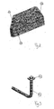
- Fig. 1 illustrates a joining device according to the invention comprising a receiving device 1, a bridge element 2 and a box element 3.
- the joining device is illustrated in a connected condition where the bridge element 2 is shown placed partly inside the receiving device 1 and partly inside the box element 3.
- the box element 3 is provided with two reinforcing rods 4 and a pipe element 5 is mounted in a wall of the box element 3.
- the individual elements constituting the joining device may be designed differently, where the receiving device 1 may merely be a cut-out in a concrete element or a box profile or the like.
- the bridge element 2 has a width, a height and a length, where the width is substantially smaller than the height and the length is in a direction from the box element to the receiving element. Furthermore, the bridge element 2 comprises a first obliquely orientated surface 21 along the edge facing upwards towards the receiving element, the purpose of this first obliquely orientated surface being to assist if the bridge element has to be returned into the box element in the event that the joining process has not achieved the desired result. At the opposite end of the bridge element 2 there is also an upwardly facing second obliquely orientated surface. This second obliquely orientated surface 22 is employed for moving the bridge element into engagement with the receiving element.
- the bridge element moreover, also comprises a locking dog 23 at a lower edge at the same end as the first obliquely orientated surface 21.
- Fig. 3 illustrates an embodiment of a reinforcing rod 4.
- a thickening portion in this case a plate element 42 that is welded or screwed to the reinforcing rod 4.
- the reinforcing rod further comprises an angled portion 41 that is designed so that two sections of the reinforcing rod form an angle of approximately 90 degrees to each other.
- the thickening portion of the reinforcing rod can be obtained in a number of ways; a threaded nut, an upsetting of the rod, a bore with through-going stop element, etc.
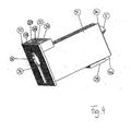
- Fig. 4 is a perspective view of an embodiment of a box element according to the invention.
- the box element comprises a beam box 31, a front plate 32 and a back plate 36.
- an attachment element 33 for attaching reinforcing rods.
- the attachment element 33 has two through-going holes 37 that have a centre axis parallel to the front plate 32 and a side plate of the beam box 31.
- the front plate 32 is extended upwards so that the upper edge of the front plate 32 is flush with the upper edge of the attachment element 33.
- the holes 37 are provided without internal threads since they are intended to cooperate with the reinforcing rods illustrated in fig. 3 which only have a plate element mounted at one end.
- the position of the holes 37 is also such that they extend on the side of the beam box 31.
- the holes 37 are also provided with a small cut slot 38 facing the front plate 32, thus substantially simplifying production.
- the front plate 32 has a slot opening 34 of a shape substantially corresponding to the bridge element's cross section, thus also providing a guide function for the bridge element 2.
- the slot opening 34 in one portion has been provided with an additional cut-out 35 or an extension.
- this cut-out is made in connection with the slot opening 34, but may well be separate from the slot opening as one or more through-going holes.
- This additional cut-out also provides access to the interior of the box element in a connected condition of the joining device where the bridge element is located partly inside the box element. This offers the capability of supplying the box element with filler, thereby securing the bridge element in the box element.
- the box element further comprises a pipe element 5 which in the illustrated embodiment is provided protruding through the back plate 36 of the box element 3.
- the pipe element 5 can also be placed through a side wall or top or bottom plate of the box element according to what is appropriate for the concrete elements concerned that have to be joined.
- the pipe element 5 has a centre axis extending at an angle relative to a guide direction for the bridge element 2, thus providing access from the top of the concrete beam.
- the pipe element can then also be used for inserting an element such as a crowbar for moving the bridge element from a retracted position in the box element to an engaged position with the receiving device, by the crowbar sliding towards the second slanting surface on the bridge element 2 (see fig. 2).
- the box element 3 may also include reinforcing elements 39 and additional attachment elements 40 for reinforcing rods 4.
- Fig. 5 illustrates an embodiment of the joining device according to the invention arranged for joining a beam 10 and a pillar 11.
- the box element 3 is mounted in the beam 10 with the front plate flush with the end edge of the beam, and a receiving device 1 is mounted in the pillar 11.
- the box element 3 is secured to the beam in the casting process by angled reinforcing rods 4 amongst other things inserted in an attachment element 33 fixed to the box element 3.
- a pipe element 5 which is extended up to a top of the beam 10.
- Between the beam 10 and the pillar 11 is a gap 12 in a connected position of the joining device.
- this gap and the interior of the box element and the receiving device can be supplied with filler by placing a gasket 13 in the lower edge of the gap and supplying filler 14 in the upper edge of the gap and in the pipe element 5.
- the filler will penetrate into the box element 3 through the pipe element 5 and also the cut-out opening in the front plate of the box element, thereby providing a secure connection between the beam 10 and the pillar 11.
- the box element may have internal control elements for the bridge element
- the bridge element may be equipped with guide rope instead of obliquely orientated surfaces
- the pipe element may extend from a top or lateral surface of the box element and at an angle to the guide device for the bridge element, there may be several through-going holes in the front plate
- the outside of the box element may contain ribs for a better attachment to the concrete
- the attachment element may comprise two or more separate parts mounted at different points on the box element
- the reinforcing rods may be upset at the end instead of containing a welded-on plate element, or they may be secured by bolts.
- the elements that have to be joined may be elements other than concrete elements, for example made of composite material or that the two elements are made of different materials such as the beam made of concrete and the pillar of a different material.
Landscapes
- Engineering & Computer Science (AREA)
- Architecture (AREA)
- Physics & Mathematics (AREA)
- Electromagnetism (AREA)
- Civil Engineering (AREA)
- Structural Engineering (AREA)
- Bridges Or Land Bridges (AREA)
- Electric Connection Of Electric Components To Printed Circuits (AREA)
- Pressure Welding/Diffusion-Bonding (AREA)
Applications Claiming Priority (2)
| Application Number | Priority Date | Filing Date | Title |
|---|---|---|---|
| NO20042767A NO321443B1 (no) | 2004-06-30 | 2004-06-30 | Sammenforingssystem, enkeltelementer og fremgangsmate for bruk av dette |
| EP05761422A EP1774110A1 (fr) | 2004-06-30 | 2005-06-22 | Systeme permettant d'assembler deux elements |
Related Parent Applications (1)
| Application Number | Title | Priority Date | Filing Date |
|---|---|---|---|
| EP05761422A Division EP1774110A1 (fr) | 2004-06-30 | 2005-06-22 | Systeme permettant d'assembler deux elements |
Publications (1)
| Publication Number | Publication Date |
|---|---|
| EP1903156A2 true EP1903156A2 (fr) | 2008-03-26 |
Family
ID=35005985
Family Applications (2)
| Application Number | Title | Priority Date | Filing Date |
|---|---|---|---|
| EP07076002A Withdrawn EP1903156A2 (fr) | 2004-06-30 | 2005-06-22 | Système permettant d'assembler deux élément et procédé d'utilisation de celui-ci |
| EP05761422A Withdrawn EP1774110A1 (fr) | 2004-06-30 | 2005-06-22 | Systeme permettant d'assembler deux elements |
Family Applications After (1)
| Application Number | Title | Priority Date | Filing Date |
|---|---|---|---|
| EP05761422A Withdrawn EP1774110A1 (fr) | 2004-06-30 | 2005-06-22 | Systeme permettant d'assembler deux elements |
Country Status (5)
| Country | Link |
|---|---|
| US (1) | US7818933B2 (fr) |
| EP (2) | EP1903156A2 (fr) |
| CA (1) | CA2571915A1 (fr) |
| NO (1) | NO321443B1 (fr) |
| WO (1) | WO2006004414A1 (fr) |
Cited By (1)
| Publication number | Priority date | Publication date | Assignee | Title |
|---|---|---|---|---|
| WO2012084327A1 (fr) * | 2010-12-21 | 2012-06-28 | Svein Berg Holding As | Configuration de système d'assemblage pour des éléments de construction |
Families Citing this family (10)
| Publication number | Priority date | Publication date | Assignee | Title |
|---|---|---|---|---|
| NO326748B1 (no) * | 2007-03-19 | 2009-02-09 | Sb Produksjon As | Anordning for sammenforing av to bygningselementer, samt anvendelse av en elastisk hylse i et bygningselement. |
| EP2951364B1 (fr) * | 2013-01-29 | 2018-03-14 | Building Service di Cenzon Francesco e Pomini Giorgio S.n.c. | Système de construction pour l'industrie du bâtiment |
| ITVR20130022A1 (it) * | 2013-01-29 | 2014-07-30 | Eiseko Engineering | Sistema di costruzione nel settore edile |
| US8950133B2 (en) * | 2013-04-29 | 2015-02-10 | Peikko Group Oy | Bracket and an arrangement for supporting a precast slab element of concrete on a precast structure element of concrete |
| BE1021992B1 (nl) * | 2014-04-22 | 2016-02-02 | B&R Nv | Inrichting en werkwijze voor het verankeren van een uitkragend element aan een constructie |
| NO344429B1 (no) * | 2017-03-07 | 2019-12-09 | Svein Berg Holding As | Innfestingsinnretning og fremgangsmåte for montering av et utkragningsdel til en bygning |
| DE102021100348A1 (de) * | 2021-01-12 | 2022-07-14 | Schöck Bauteile GmbH | Vorrichtung zum kraftübertragenden Verbinden eines ersten tragenden Gebäudeteils mit einem zweiten getragenen Gebäudeteil |
| CN112942946A (zh) * | 2021-02-05 | 2021-06-11 | 绍兴文理学院 | 一种装配式榫卯牛腿型梁柱节点连接方法 |
| KR102853849B1 (ko) * | 2023-09-15 | 2025-09-02 | 삼성물산(주) | 철골브라켓을 이용한 pc기둥과 pc보의 내진접합부 구조 |
| US12497773B1 (en) * | 2025-07-26 | 2025-12-16 | Francisco A Adames T | Deployable extender assembly |
Family Cites Families (6)
| Publication number | Priority date | Publication date | Assignee | Title |
|---|---|---|---|---|
| US3733757A (en) * | 1971-07-30 | 1973-05-22 | Flexicore Co | Concrete building frame construction |
| CA1303379C (fr) | 1987-04-07 | 1992-06-16 | Bjorn O. Thoresen | Construction de batiment |
| SE457221B (sv) | 1987-04-10 | 1988-12-05 | Straengbetong Ab | Upplagsdon foer uppslagssamverkan mellan en baerande konstruktionsdel och en buren konstruktionsdel |
| US4903448A (en) * | 1989-07-21 | 1990-02-27 | Kabo-Karr Corporation Of California | Retractable hangers for mounting precast concrete beams and the like in buildings |
| DE19602306B4 (de) * | 1996-01-23 | 2004-02-19 | Schöck Entwicklungsgesellschaft mbH | Tragvorrichtung |
| ES2319261T3 (es) | 2002-10-03 | 2009-05-06 | Tartuntamarkkinointi Oy | Junta del tipo de consola oculta. |
-
2004
- 2004-06-30 NO NO20042767A patent/NO321443B1/no not_active IP Right Cessation
-
2005
- 2005-06-22 CA CA002571915A patent/CA2571915A1/fr not_active Abandoned
- 2005-06-22 WO PCT/NO2005/000220 patent/WO2006004414A1/fr not_active Ceased
- 2005-06-22 EP EP07076002A patent/EP1903156A2/fr not_active Withdrawn
- 2005-06-22 EP EP05761422A patent/EP1774110A1/fr not_active Withdrawn
- 2005-06-22 US US11/570,969 patent/US7818933B2/en not_active Expired - Fee Related
Cited By (2)
| Publication number | Priority date | Publication date | Assignee | Title |
|---|---|---|---|---|
| WO2012084327A1 (fr) * | 2010-12-21 | 2012-06-28 | Svein Berg Holding As | Configuration de système d'assemblage pour des éléments de construction |
| US8881487B2 (en) | 2010-12-21 | 2014-11-11 | Svein Berg Holding As | Joining system arrangement for building elements |
Also Published As
| Publication number | Publication date |
|---|---|
| US20090165413A1 (en) | 2009-07-02 |
| NO20042767D0 (no) | 2004-06-30 |
| CA2571915A1 (fr) | 2006-01-12 |
| US7818933B2 (en) | 2010-10-26 |
| NO20042767L (no) | 2006-01-02 |
| WO2006004414A1 (fr) | 2006-01-12 |
| NO321443B1 (no) | 2006-05-08 |
| EP1774110A1 (fr) | 2007-04-18 |
Similar Documents
| Publication | Publication Date | Title |
|---|---|---|
| EP1903156A2 (fr) | Système permettant d'assembler deux élément et procédé d'utilisation de celui-ci | |
| US20100313518A1 (en) | Joining device | |
| US20080279620A1 (en) | Joining System and Use of this System | |
| US20080107480A1 (en) | Joining system, individual elements and method for use thereof | |
| CN110409795A (zh) | 一种铝模板结构 | |
| EP2183442A1 (fr) | Système d'assemblage pour deux éléments de construction | |
| CN210002610U (zh) | 一种用于装配式剪力墙的盒式连接结构体系 | |
| CN105637159A (zh) | 模板元件 | |
| JP6993372B2 (ja) | オープンシールド機 | |
| EP1896670A1 (fr) | Connecteurs de renforcement en beton | |
| JP6144304B2 (ja) | 分離帯構造体 | |
| CN114508232B (zh) | 一种船式屋顶构架端部挑梁施工工艺 | |
| JP2006169764A (ja) | 盛土用の面状材付き発泡樹脂ブロック及びそれを用いた軽量盛土構造 | |
| US20050268564A1 (en) | Modular window well | |
| KR101008411B1 (ko) | 조립식 거푸집패널 | |
| JP2000064289A (ja) | コンクリート埋込ジョイント及び壁面を有する盛土の補強工法 | |
| KR200177205Y1 (ko) | 낙석방지용 보강휀스 | |
| JP2001164684A (ja) | プレキャストコンクリートカーテンウォールの取付方法 | |
| KR100561081B1 (ko) | 무해체 계단 거푸집 | |
| IE20190110A2 (en) | Precast building element connector | |
| IE87352B1 (en) | Precast building element connector | |
| CN210002611U (zh) | 一种用于l型装配式剪力墙的盒式连接节点构造 | |
| WO1991006721A1 (fr) | Raccordement entre une poutre ou une console tubulaire et un montant tubulaire | |
| EP2225421B1 (fr) | Système d'assemblage pour éléments de construction | |
| KR100236708B1 (ko) | 거푸집틀을 이용한 현수식 무지보 역타설 지하구축시스템 |
Legal Events
| Date | Code | Title | Description |
|---|---|---|---|
| PUAI | Public reference made under article 153(3) epc to a published international application that has entered the european phase |
Free format text: ORIGINAL CODE: 0009012 |
|
| AC | Divisional application: reference to earlier application |
Ref document number: 1774110 Country of ref document: EP Kind code of ref document: P |
|
| AK | Designated contracting states |
Kind code of ref document: A2 Designated state(s): AT BE BG CH CY CZ DE DK EE ES FI FR GB GR HU IE IS IT LI LT LU MC NL PL PT RO SE SI SK TR |
|
| STAA | Information on the status of an ep patent application or granted ep patent |
Free format text: STATUS: THE APPLICATION IS DEEMED TO BE WITHDRAWN |
|
| 18D | Application deemed to be withdrawn |
Effective date: 20140103 |