EP1903185A2 - Wärme- und außenlastisolierende Laufraddeckscheibe - Google Patents
Wärme- und außenlastisolierende Laufraddeckscheibe Download PDFInfo
- Publication number
- EP1903185A2 EP1903185A2 EP07253641A EP07253641A EP1903185A2 EP 1903185 A2 EP1903185 A2 EP 1903185A2 EP 07253641 A EP07253641 A EP 07253641A EP 07253641 A EP07253641 A EP 07253641A EP 1903185 A2 EP1903185 A2 EP 1903185A2
- Authority
- EP
- European Patent Office
- Prior art keywords
- impeller
- impeller shroud
- support bracket
- shroud
- gas turbine
- Prior art date
- Legal status (The legal status is an assumption and is not a legal conclusion. Google has not performed a legal analysis and makes no representation as to the accuracy of the status listed.)
- Granted
Links
Images

Classifications
-
- F—MECHANICAL ENGINEERING; LIGHTING; HEATING; WEAPONS; BLASTING
- F04—POSITIVE - DISPLACEMENT MACHINES FOR LIQUIDS; PUMPS FOR LIQUIDS OR ELASTIC FLUIDS
- F04D—NON-POSITIVE-DISPLACEMENT PUMPS
- F04D29/00—Details, component parts, or accessories
- F04D29/40—Casings; Connections of working fluid
- F04D29/42—Casings; Connections of working fluid for radial or helico-centrifugal pumps
- F04D29/4206—Casings; Connections of working fluid for radial or helico-centrifugal pumps especially adapted for elastic fluid pumps
-
- F—MECHANICAL ENGINEERING; LIGHTING; HEATING; WEAPONS; BLASTING
- F01—MACHINES OR ENGINES IN GENERAL; ENGINE PLANTS IN GENERAL; STEAM ENGINES
- F01D—NON-POSITIVE DISPLACEMENT MACHINES OR ENGINES, e.g. STEAM TURBINES
- F01D11/00—Preventing or minimising internal leakage of working-fluid, e.g. between stages
- F01D11/08—Preventing or minimising internal leakage of working-fluid, e.g. between stages for sealing space between rotor blade tips and stator
- F01D11/14—Adjusting or regulating tip-clearance, i.e. distance between rotor-blade tips and stator casing
- F01D11/16—Adjusting or regulating tip-clearance, i.e. distance between rotor-blade tips and stator casing by self-adjusting means
-
- F—MECHANICAL ENGINEERING; LIGHTING; HEATING; WEAPONS; BLASTING
- F01—MACHINES OR ENGINES IN GENERAL; ENGINE PLANTS IN GENERAL; STEAM ENGINES
- F01D—NON-POSITIVE DISPLACEMENT MACHINES OR ENGINES, e.g. STEAM TURBINES
- F01D25/00—Component parts, details, or accessories, not provided for in, or of interest apart from, other groups
- F01D25/24—Casings; Casing parts, e.g. diaphragms, casing fastenings
- F01D25/246—Fastening of diaphragms or stator-rings
-
- F—MECHANICAL ENGINEERING; LIGHTING; HEATING; WEAPONS; BLASTING
- F01—MACHINES OR ENGINES IN GENERAL; ENGINE PLANTS IN GENERAL; STEAM ENGINES
- F01D—NON-POSITIVE DISPLACEMENT MACHINES OR ENGINES, e.g. STEAM TURBINES
- F01D5/00—Blades; Blade-carrying members; Heating, heat-insulating, cooling or antivibration means on the blades or the members
- F01D5/02—Blade-carrying members, e.g. rotors
- F01D5/04—Blade-carrying members, e.g. rotors for radial-flow machines or engines
- F01D5/043—Blade-carrying members, e.g. rotors for radial-flow machines or engines of the axial inlet- radial outlet, or vice versa, type
-
- F—MECHANICAL ENGINEERING; LIGHTING; HEATING; WEAPONS; BLASTING
- F04—POSITIVE - DISPLACEMENT MACHINES FOR LIQUIDS; PUMPS FOR LIQUIDS OR ELASTIC FLUIDS
- F04D—NON-POSITIVE-DISPLACEMENT PUMPS
- F04D29/00—Details, component parts, or accessories
- F04D29/60—Mounting; Assembling; Disassembling
- F04D29/62—Mounting; Assembling; Disassembling of radial or helico-centrifugal pumps
- F04D29/624—Mounting; Assembling; Disassembling of radial or helico-centrifugal pumps especially adapted for elastic fluid pumps
-
- F—MECHANICAL ENGINEERING; LIGHTING; HEATING; WEAPONS; BLASTING
- F05—INDEXING SCHEMES RELATING TO ENGINES OR PUMPS IN VARIOUS SUBCLASSES OF CLASSES F01-F04
- F05B—INDEXING SCHEME RELATING TO WIND, SPRING, WEIGHT, INERTIA OR LIKE MOTORS, TO MACHINES OR ENGINES FOR LIQUIDS COVERED BY SUBCLASSES F03B, F03D AND F03G
- F05B2260/00—Function
- F05B2260/30—Retaining components in desired mutual position
- F05B2260/301—Retaining bolts or nuts
-
- F—MECHANICAL ENGINEERING; LIGHTING; HEATING; WEAPONS; BLASTING
- F05—INDEXING SCHEMES RELATING TO ENGINES OR PUMPS IN VARIOUS SUBCLASSES OF CLASSES F01-F04
- F05D—INDEXING SCHEME FOR ASPECTS RELATING TO NON-POSITIVE-DISPLACEMENT MACHINES OR ENGINES, GAS-TURBINES OR JET-PROPULSION PLANTS
- F05D2230/00—Manufacture
- F05D2230/60—Assembly methods
- F05D2230/64—Assembly methods using positioning or alignment devices for aligning or centring, e.g. pins
- F05D2230/642—Assembly methods using positioning or alignment devices for aligning or centring, e.g. pins using maintaining alignment while permitting differential dilatation
-
- F—MECHANICAL ENGINEERING; LIGHTING; HEATING; WEAPONS; BLASTING
- F05—INDEXING SCHEMES RELATING TO ENGINES OR PUMPS IN VARIOUS SUBCLASSES OF CLASSES F01-F04
- F05D—INDEXING SCHEME FOR ASPECTS RELATING TO NON-POSITIVE-DISPLACEMENT MACHINES OR ENGINES, GAS-TURBINES OR JET-PROPULSION PLANTS
- F05D2250/00—Geometry
- F05D2250/70—Shape
-
- Y—GENERAL TAGGING OF NEW TECHNOLOGICAL DEVELOPMENTS; GENERAL TAGGING OF CROSS-SECTIONAL TECHNOLOGIES SPANNING OVER SEVERAL SECTIONS OF THE IPC; TECHNICAL SUBJECTS COVERED BY FORMER USPC CROSS-REFERENCE ART COLLECTIONS [XRACs] AND DIGESTS
- Y02—TECHNOLOGIES OR APPLICATIONS FOR MITIGATION OR ADAPTATION AGAINST CLIMATE CHANGE
- Y02T—CLIMATE CHANGE MITIGATION TECHNOLOGIES RELATED TO TRANSPORTATION
- Y02T50/00—Aeronautics or air transport
- Y02T50/60—Efficient propulsion technologies, e.g. for aircraft
Definitions
- the invention relates generally to gas turbine engines and, more particularly, to impeller shrouds of gas turbine engines.
- Gas turbine engines such as those used as aircraft turbojets or turbofans typically comprise a rotating fan, a low-pressure compressor and a high-pressure compressor as well as high-pressure and low-pressure turbines that are axially mounted to separate coaxial shafts for rotation about a central axis of the engine.
- the high-pressure compressor typically includes a set of multiple axial stage rotors followed by a centrifugal impeller. Enshrouding the blades of the centrifugal impeller is a static impeller shroud.
- the impeller shroud is typically mounted to one of the engine cases in the compressor section such as, for example, by means of a strut that extends from the impeller shroud radially outwardly to the inner case of the bypass duct.
- the strut secures the impeller shroud in place relative to the impeller blades so that there is a minimal clearance between the impeller blades and the impeller shroud. Minimizing the clearance between the impeller blades and the impeller shroud is instrumental in optimizing the capacity of the impeller to pressurize the air to the elevated pressures required for high engine performance.
- the impeller shroud may deflect.
- External loads include externally applied loads from the assembly fit as well transient operating conditions. Deflections of the impeller shroud are most pronounced at the tip of the shroud. Likewise, the deflections and distortions of the impeller blades due to thermal effects and centrifugal loading is most pronounced at the tips of the blades. Therefore, controlling variations in the tip clearance, i.e. the gap between the tip of the impeller blades and the impeller shroud as these two components move relative to each other, is critical to optimizing pressurization and thus engine performance.
- tip clearance should be tight enough to ensure strong pressurization of the air discharging from the impeller but it must not be so tight that there is a risk that deflections of the impeller shroud relative to the impeller (due to extreme thermal or other loads) can cause the blades and the shroud to come into contact with each other.
- the present invention provides a gas turbine engine comprising a compressor assembly and a turbine assembly rotationally mounted on a shaft, the turbine assembly being driven by hot gases discharged from a combustion chamber disposed between the compressor and turbine assemblies, the compressor having a centrifugal impeller for pressurizing and impelling air into the combustion chamber.
- the engine also includes an impeller shroud covering the centrifugal impeller, the impeller shroud having a support bracket having a thin and curved load-isolating profile for supporting a strut that secures the impeller shroud to a case of the engine.
- the present invention provides an impeller shroud for use with a centrifugal impeller of a high-pressure compressor of a gas turbine engine.
- the impeller shroud comprises a support bracket mounted to the impeller shroud, the support bracket having a thin and curved load-isolating profile and means for securing the support bracket to a case of the gas turbine engine.
- the present invention provides a method of installing an impeller shroud for controlling tip clearance between impeller blades of a centrifugal impeller and an impeller shroud.
- the method comprises steps of providing a load-isolating support bracket on the impeller shroud, the support bracket having a thin and curved load-isolating profile and securing the impeller shroud relative to the impeller blades by connecting the load-isolating support bracket to an engine case whereby thermal and other external loads are attenuated by the load-isolating support bracket.
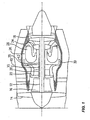
- a turbofan gas turbine engine incorporating an embodiment of the present invention is presented as an example of the application of the present invention, and includes a housing 10, a core casing 13, a low pressure spool assembly seen generally at 12 which includes a shaft 15 interconnecting a fan assembly 14, a low pressure compressor 16 and a low pressure turbine assembly 18, and a high pressure spool assembly seen generally at 20 which includes a shaft at 25 interconnecting a high pressure compressor assembly 22 and a high pressure turbine assembly 24.
- the core casing 13 surrounds the low and high pressure spool assemblies 12 and 20 in order to define a main fluid path (not indicated) therethrough.
- a combustion section 26 having a combustor 28 therein. Pressurized air provided by the high pressure compressor assembly 22 through a diffuser 30 enters the combustion section 26 for combustion taking place in the combustor 28.
- FIG. 2 shows, in cross section, an impeller shroud 40 in accordance with an embodiment of the present invention.
- the impeller shroud 40 covers, or “enshrouds", the blades of the centrifugal impeller 50.
- the impeller rotates between the impeller shroud 40 and a backface 52 that extends outwardly from a hub to which the compressor is mounted.
- the impeller pressurizes and impels air into the combustion chamber from which hot gases are discharged to drive the turbine assembly.
- TC tip clearance
- the impeller shroud 40 has a support bracket 60 mounted to the impeller shroud 40, the support bracket 60 having a thin and curved load-isolating profile.
- the impeller shroud 40 also includes means for securing the support bracket 60 to a case 70 of the gas turbine engine.
- the support bracket 60 has a hairpin shape although other thin and curved profiles could also be utilized.
- the hairpin support bracket is integrally formed with the impeller shroud.
- the hairpin support bracket could be welded or fastened to the impeller shroud.
- the integrally formed hairpin-shaped bracket has a lower extension member 62 that extends axially forward from the impeller shroud and a semicircular curved portion 64 connecting the lower extension member 62 to an upper support member 66 that is adapted to support a means for securing 68 the impeller shroud to a case 70 of the engine.
- the lower extension member 62 and the upper support member 66 are both substantially parallel to the shaft 25 (shown in Figure 1) supporting the compressor and turbine assemblies.
- the means for securing 68 can include a strut 72 for securing the impeller shroud 40 to an inner case of a bypass duct.
- the means for securing 68 also comprises a spigot 74 for fastening the support bracket 60 to the strut 72.
- the hairpin-shaped support bracket 60 has a shoulder 69 for supporting a flange 73 of the strut 72.
- the upper support member 66 can be used to support a flange 76 of a buttress member 78 that buttresses a tangential annular diffuser 80.
- the tangential annular diffuser 80 is in close proximity to the tip 54 of the impeller blades 50 (into which the impeller discharges highly compressed air) and has an exit that discharges into the combustion chamber.
- the thin and curved profile of the impeller shroud 40 when installed in a gas turbine engine, such as the turbofan shown in Figure 1, isolates the impeller shroud from thermal and other external loads (transient operating conditions, loads due to the assembly fit, etc.) which can cause the tip clearance TC to vary beyond the close tolerances required for optimized engine performance.
- vibrations and loads due to thermal effects or installation loads are substantially attenuated by the thin, curved profile of the support bracket, resulting in only minimal forces being transferred to or from the impeller shroud.
- the load-isolating support bracket therefore diminishes the deflections of the impeller shroud relative to the impeller. Accordingly, the tolerance of the gap between the impeller tip and the shroud (i.e. the tip clearance TC) can be tightened, thus enhancing performance of the engine.
- the foregoing also provides a method of installing an impeller shroud for controlling tip clearance between impeller blades of a centrifugal impeller and an impeller shroud.
- the method includes steps of providing a load-isolating support bracket on the impeller shroud, the support bracket having a thin and curved load-isolating profile.
- An existing gas turbine engine could be retrofitted with an improved impeller shroud to isolate the shroud from thermal and other external loads.
- the impeller shroud is then secured relative to the impeller blades by connecting the load-isolating support bracket to an engine case whereby thermal and other external loads are attenuated by the load-isolating support bracket.
- impeller baffle can be used not only for turbofans or turbojets, but also for turboprops, turboshafts or any other gas turbine engine. Still other modifications which fall within the scope of the present invention will be apparent to those skilled in the art, in light of a review of this disclosure, and such modifications are intended to fall within the appended claims.
Landscapes
- Engineering & Computer Science (AREA)
- Mechanical Engineering (AREA)
- General Engineering & Computer Science (AREA)
- Structures Of Non-Positive Displacement Pumps (AREA)
Applications Claiming Priority (1)
| Application Number | Priority Date | Filing Date | Title |
|---|---|---|---|
| US11/532,564 US7908869B2 (en) | 2006-09-18 | 2006-09-18 | Thermal and external load isolating impeller shroud |
Publications (3)
| Publication Number | Publication Date |
|---|---|
| EP1903185A2 true EP1903185A2 (de) | 2008-03-26 |
| EP1903185A3 EP1903185A3 (de) | 2012-05-09 |
| EP1903185B1 EP1903185B1 (de) | 2013-06-19 |
Family
ID=39000669
Family Applications (1)
| Application Number | Title | Priority Date | Filing Date |
|---|---|---|---|
| EP07253641.0A Not-in-force EP1903185B1 (de) | 2006-09-18 | 2007-09-13 | Wärme- und außenlastisolierende Laufraddeckscheibe |
Country Status (4)
| Country | Link |
|---|---|
| US (1) | US7908869B2 (de) |
| EP (1) | EP1903185B1 (de) |
| CA (1) | CA2663063C (de) |
| WO (1) | WO2008034218A1 (de) |
Cited By (4)
| Publication number | Priority date | Publication date | Assignee | Title |
|---|---|---|---|---|
| FR2931521A1 (fr) * | 2008-05-26 | 2009-11-27 | Turbomeca | Couvercle de compresseur a butee axiale. |
| WO2012052687A1 (fr) * | 2010-10-21 | 2012-04-26 | Turbomeca | Procede d'attache de couvercle de compresseur centrifuge de turbomachine, couvercle de compresseur de mise en oeuvre et assemblage de compresseur muni d'un tel couvercle |
| WO2014053722A1 (fr) * | 2012-10-05 | 2014-04-10 | Turbomeca | Couvercle de compresseur centrifuge, assemblage de couvercle et de compresseur centrifuge, et turbomachine comportant un tel assemblage |
| FR3006369A1 (fr) * | 2013-06-04 | 2014-12-05 | Snecma | Turbomachine a etage de compression centrifuge |
Families Citing this family (12)
| Publication number | Priority date | Publication date | Assignee | Title |
|---|---|---|---|---|
| JP5112098B2 (ja) * | 2008-02-05 | 2013-01-09 | 株式会社リコー | 光走査装置及び画像形成装置 |
| FR2927951B1 (fr) * | 2008-02-27 | 2011-08-19 | Snecma | Ensemble diffuseur-redresseur pour une turbomachine |
| FR2952126B1 (fr) * | 2009-11-04 | 2011-12-23 | Snecma | Turbomachine a double flux pour aeronef, comprenant des moyens structuraux de rigidification du carter central |
| WO2014133616A1 (en) | 2013-03-01 | 2014-09-04 | Rolls-Royce North American Technologies,Inc. | Gas turbine engine impeller system for an intermediate pressure (ip) compressor |
| EP2964960B1 (de) | 2013-03-08 | 2019-06-12 | Rolls-Royce North American Technologies, Inc. | Turbostrahltriebwerk-radialverdichter mit dichtung zwischen zwei diffusorteilen |
| US9298778B2 (en) * | 2013-05-14 | 2016-03-29 | Google Inc. | Presenting related content in a stream of content |
| DE102015220333A1 (de) * | 2015-10-19 | 2017-04-20 | Rolls-Royce Deutschland Ltd & Co Kg | Vorrichtung zur Einstellung eines Spaltes zwischen dem Gehäuse eines Laufrades und dem Laufrad in einem Radialverdichter und eine Turbomaschine |
| CN108443227B (zh) * | 2018-05-24 | 2020-05-05 | 中国科学院工程热物理研究所 | 一种防止离心叶轮刮蹭的机匣波纹结构 |
| US10704560B2 (en) * | 2018-06-13 | 2020-07-07 | Rolls-Royce Corporation | Passive clearance control for a centrifugal impeller shroud |
| CN109915415B (zh) * | 2019-04-11 | 2020-09-22 | 中国航发湖南动力机械研究所 | 具有包容结构的负载压气机 |
| US11441516B2 (en) | 2020-07-14 | 2022-09-13 | Rolls-Royce North American Technologies Inc. | Centrifugal compressor assembly for a gas turbine engine with deswirler having sealing features |
| US20260028936A1 (en) * | 2024-07-25 | 2026-01-29 | Pratt & Whitney Canada Corp. | Shroud arrestor for bladed powerplant rotor |
Family Cites Families (12)
| Publication number | Priority date | Publication date | Assignee | Title |
|---|---|---|---|---|
| US4248566A (en) * | 1978-10-06 | 1981-02-03 | General Motors Corporation | Dual function compressor bleed |
| US4264271A (en) * | 1979-03-15 | 1981-04-28 | Avco Corporation | Impeller shroud of a centrifugal compressor |
| GB2114661B (en) * | 1980-10-21 | 1984-08-01 | Rolls Royce | Casing structure for a gas turbine engine |
| GB2117843B (en) * | 1982-04-01 | 1985-11-06 | Rolls Royce | Compressor shrouds |
| US4687412A (en) * | 1985-07-03 | 1987-08-18 | Pratt & Whitney Canada Inc. | Impeller shroud |
| GB9317530D0 (en) * | 1993-08-21 | 1993-10-06 | Westland Helicopters | Fusible support devices for rotating shafts |
| US5601406A (en) * | 1994-12-21 | 1997-02-11 | Alliedsignal Inc. | Centrifugal compressor hub containment assembly |
| US5619850A (en) * | 1995-05-09 | 1997-04-15 | Alliedsignal Inc. | Gas turbine engine with bleed air buffer seal |
| JP4625158B2 (ja) * | 2000-05-29 | 2011-02-02 | 本田技研工業株式会社 | 遠心式コンプレッサ |
| US7097411B2 (en) * | 2004-04-20 | 2006-08-29 | Honeywell International, Inc. | Turbomachine compressor scroll with load-carrying inlet vanes |
| US7093418B2 (en) * | 2004-04-21 | 2006-08-22 | Honeywell International, Inc. | Gas turbine engine including a low pressure sump seal buffer source and thermally isolated sump |
| US7363762B2 (en) * | 2005-11-16 | 2008-04-29 | General Electric Company | Gas turbine engines seal assembly and methods of assembling the same |
-
2006
- 2006-09-18 US US11/532,564 patent/US7908869B2/en active Active
-
2007
- 2007-09-07 CA CA2663063A patent/CA2663063C/en not_active Expired - Fee Related
- 2007-09-07 WO PCT/CA2007/001591 patent/WO2008034218A1/en not_active Ceased
- 2007-09-13 EP EP07253641.0A patent/EP1903185B1/de not_active Not-in-force
Cited By (10)
| Publication number | Priority date | Publication date | Assignee | Title |
|---|---|---|---|---|
| FR2931521A1 (fr) * | 2008-05-26 | 2009-11-27 | Turbomeca | Couvercle de compresseur a butee axiale. |
| WO2009153478A3 (fr) * | 2008-05-26 | 2010-05-27 | Turbomeca | Couvercle de compresseur de turbomoteur a butee axiale |
| US8721261B2 (en) | 2008-05-26 | 2014-05-13 | Turbomeca | Compressor cover for turbine engine having axial abutment |
| WO2012052687A1 (fr) * | 2010-10-21 | 2012-04-26 | Turbomeca | Procede d'attache de couvercle de compresseur centrifuge de turbomachine, couvercle de compresseur de mise en oeuvre et assemblage de compresseur muni d'un tel couvercle |
| FR2966529A1 (fr) * | 2010-10-21 | 2012-04-27 | Turbomeca | Procede d’attache de couvercle de compresseur centrifuge de turbomachine, couvercle de compresseur de mise en oeuvre et assemblage de compresseur muni d’un tel couvercle |
| CN103201461A (zh) * | 2010-10-21 | 2013-07-10 | 涡轮梅坎公司 | 安装涡轮发动机离心压缩机盖子的方法、实施这种方法的压缩机盖子以及具有这种盖子的压缩机组件 |
| US9409228B2 (en) | 2010-10-21 | 2016-08-09 | Turbomeca | Method for attaching the cover of a centrifugal compressor of a turbine engine, compressor cover implementing same and compressor assembly provided with such a cover |
| WO2014053722A1 (fr) * | 2012-10-05 | 2014-04-10 | Turbomeca | Couvercle de compresseur centrifuge, assemblage de couvercle et de compresseur centrifuge, et turbomachine comportant un tel assemblage |
| FR2996608A1 (fr) * | 2012-10-05 | 2014-04-11 | Turbomeca | Couvercle de compresseur centrifuge, assemblage de couvercle et de compresseur centrifuge, et turbomachine comportant un tel assemblage |
| FR3006369A1 (fr) * | 2013-06-04 | 2014-12-05 | Snecma | Turbomachine a etage de compression centrifuge |
Also Published As
| Publication number | Publication date |
|---|---|
| WO2008034218A1 (en) | 2008-03-27 |
| EP1903185A3 (de) | 2012-05-09 |
| EP1903185B1 (de) | 2013-06-19 |
| US20080069690A1 (en) | 2008-03-20 |
| US7908869B2 (en) | 2011-03-22 |
| CA2663063C (en) | 2012-02-07 |
| CA2663063A1 (en) | 2008-03-27 |
Similar Documents
| Publication | Publication Date | Title |
|---|---|---|
| EP1903185B1 (de) | Wärme- und außenlastisolierende Laufraddeckscheibe | |
| US7775758B2 (en) | Impeller rear cavity thrust adjustor | |
| EP3081759B1 (de) | Ummantelungsanordnung und ummantelung für gasturbinenmotor | |
| US8596965B2 (en) | Gas turbine engine compressor case mounting arrangement | |
| US10301960B2 (en) | Shroud assembly for gas turbine engine | |
| RU2481499C2 (ru) | Узел диффузор-направляющий аппарат для турбомашины | |
| EP1924758B1 (de) | Schaufelanordnung mit aussentülle | |
| US10961850B2 (en) | Rotatable torque frame for gas turbine engine | |
| US8162615B2 (en) | Split disk assembly for a gas turbine engine | |
| US10544793B2 (en) | Thermal isolation structure for rotating turbine frame | |
| EP1926887B1 (de) | Schaufelanordnung mit verbesserten schaufelfüssen | |
| EP2881544A1 (de) | Schaufelprofil für eine Gasturbine und zugehörige Anordnung | |
| CN106437883A (zh) | 用于支承涡轮护罩的系统及方法 | |
| EP3287605B1 (de) | Kranzdichtung für gasturbinenmotor | |
| KR101629524B1 (ko) | 축 방향 접촉부를 갖는 터빈엔진의 압축기 커버 | |
| US11215084B2 (en) | Support straps and method of assembly for gas turbine engine | |
| US20250172095A1 (en) | Turbomachine with axial thrust management | |
| CN121100218A (zh) | 涡轮发动机涡轮用叶片及相应的转子、涡轮和涡轮发动机 | |
| CA2597443A1 (en) | Vane assembly with improved vane roots | |
| CA2597268A1 (en) | Vane assembly with outer grommets |
Legal Events
| Date | Code | Title | Description |
|---|---|---|---|
| PUAI | Public reference made under article 153(3) epc to a published international application that has entered the european phase |
Free format text: ORIGINAL CODE: 0009012 |
|
| AK | Designated contracting states |
Kind code of ref document: A2 Designated state(s): AT BE BG CH CY CZ DE DK EE ES FI FR GB GR HU IE IS IT LI LT LU LV MC MT NL PL PT RO SE SI SK TR |
|
| AX | Request for extension of the european patent |
Extension state: AL BA HR MK YU |
|
| PUAL | Search report despatched |
Free format text: ORIGINAL CODE: 0009013 |
|
| AK | Designated contracting states |
Kind code of ref document: A3 Designated state(s): AT BE BG CH CY CZ DE DK EE ES FI FR GB GR HU IE IS IT LI LT LU LV MC MT NL PL PT RO SE SI SK TR |
|
| AX | Request for extension of the european patent |
Extension state: AL BA HR MK RS |
|
| RIC1 | Information provided on ipc code assigned before grant |
Ipc: F04D 29/62 20060101ALI20120403BHEP Ipc: F04D 17/02 20060101ALI20120403BHEP Ipc: F01D 5/04 20060101ALI20120403BHEP Ipc: F01D 25/24 20060101ALI20120403BHEP Ipc: F04D 29/42 20060101ALI20120403BHEP Ipc: F01D 11/16 20060101AFI20120403BHEP |
|
| 17P | Request for examination filed |
Effective date: 20121106 |
|
| GRAP | Despatch of communication of intention to grant a patent |
Free format text: ORIGINAL CODE: EPIDOSNIGR1 |
|
| RIC1 | Information provided on ipc code assigned before grant |
Ipc: F01D 25/24 20060101ALI20121203BHEP Ipc: F01D 5/04 20060101ALI20121203BHEP Ipc: F04D 29/42 20060101ALI20121203BHEP Ipc: F01D 11/16 20060101AFI20121203BHEP Ipc: F04D 29/62 20060101ALI20121203BHEP Ipc: F04D 17/02 20060101ALI20121203BHEP |
|
| AKX | Designation fees paid |
Designated state(s): DE FR GB |
|
| GRAS | Grant fee paid |
Free format text: ORIGINAL CODE: EPIDOSNIGR3 |
|
| GRAA | (expected) grant |
Free format text: ORIGINAL CODE: 0009210 |
|
| AK | Designated contracting states |
Kind code of ref document: B1 Designated state(s): DE FR GB |
|
| REG | Reference to a national code |
Ref country code: GB Ref legal event code: FG4D |
|
| REG | Reference to a national code |
Ref country code: DE Ref legal event code: R096 Ref document number: 602007031101 Country of ref document: DE Effective date: 20130814 |
|
| PLBE | No opposition filed within time limit |
Free format text: ORIGINAL CODE: 0009261 |
|
| STAA | Information on the status of an ep patent application or granted ep patent |
Free format text: STATUS: NO OPPOSITION FILED WITHIN TIME LIMIT |
|
| 26N | No opposition filed |
Effective date: 20140320 |
|
| REG | Reference to a national code |
Ref country code: DE Ref legal event code: R097 Ref document number: 602007031101 Country of ref document: DE Effective date: 20140320 |
|
| REG | Reference to a national code |
Ref country code: FR Ref legal event code: PLFP Year of fee payment: 10 |
|
| REG | Reference to a national code |
Ref country code: DE Ref legal event code: R082 Ref document number: 602007031101 Country of ref document: DE Representative=s name: SCHMITT-NILSON SCHRAUD WAIBEL WOHLFROM PATENTA, DE |
|
| REG | Reference to a national code |
Ref country code: FR Ref legal event code: PLFP Year of fee payment: 11 |
|
| REG | Reference to a national code |
Ref country code: FR Ref legal event code: PLFP Year of fee payment: 12 |
|
| PGFP | Annual fee paid to national office [announced via postgrant information from national office to epo] |
Ref country code: DE Payment date: 20190820 Year of fee payment: 13 Ref country code: FR Payment date: 20190820 Year of fee payment: 13 |
|
| PGFP | Annual fee paid to national office [announced via postgrant information from national office to epo] |
Ref country code: GB Payment date: 20190820 Year of fee payment: 13 |
|
| REG | Reference to a national code |
Ref country code: DE Ref legal event code: R119 Ref document number: 602007031101 Country of ref document: DE |
|
| GBPC | Gb: european patent ceased through non-payment of renewal fee |
Effective date: 20200913 |
|
| PG25 | Lapsed in a contracting state [announced via postgrant information from national office to epo] |
Ref country code: FR Free format text: LAPSE BECAUSE OF NON-PAYMENT OF DUE FEES Effective date: 20200930 Ref country code: DE Free format text: LAPSE BECAUSE OF NON-PAYMENT OF DUE FEES Effective date: 20210401 |
|
| PG25 | Lapsed in a contracting state [announced via postgrant information from national office to epo] |
Ref country code: GB Free format text: LAPSE BECAUSE OF NON-PAYMENT OF DUE FEES Effective date: 20200913 |