EP1903256B1 - Motorgesteuerter Schwenkantrieb - Google Patents
Motorgesteuerter Schwenkantrieb Download PDFInfo
- Publication number
- EP1903256B1 EP1903256B1 EP07016844A EP07016844A EP1903256B1 EP 1903256 B1 EP1903256 B1 EP 1903256B1 EP 07016844 A EP07016844 A EP 07016844A EP 07016844 A EP07016844 A EP 07016844A EP 1903256 B1 EP1903256 B1 EP 1903256B1
- Authority
- EP
- European Patent Office
- Prior art keywords
- drive
- pivoting movement
- movement according
- hub
- housing
- Prior art date
- Legal status (The legal status is an assumption and is not a legal conclusion. Google has not performed a legal analysis and makes no representation as to the accuracy of the status listed.)
- Active
Links
Images
Classifications
-
- F—MECHANICAL ENGINEERING; LIGHTING; HEATING; WEAPONS; BLASTING
- F16—ENGINEERING ELEMENTS AND UNITS; GENERAL MEASURES FOR PRODUCING AND MAINTAINING EFFECTIVE FUNCTIONING OF MACHINES OR INSTALLATIONS; THERMAL INSULATION IN GENERAL
- F16H—GEARING
- F16H25/00—Gearings comprising primarily only cams, cam-followers and screw-and-nut mechanisms
- F16H25/18—Gearings comprising primarily only cams, cam-followers and screw-and-nut mechanisms for conveying or interconverting oscillating or reciprocating motions
- F16H25/20—Screw mechanisms
-
- F—MECHANICAL ENGINEERING; LIGHTING; HEATING; WEAPONS; BLASTING
- F16—ENGINEERING ELEMENTS AND UNITS; GENERAL MEASURES FOR PRODUCING AND MAINTAINING EFFECTIVE FUNCTIONING OF MACHINES OR INSTALLATIONS; THERMAL INSULATION IN GENERAL
- F16K—VALVES; TAPS; COCKS; ACTUATING-FLOATS; DEVICES FOR VENTING OR AERATING
- F16K31/00—Actuating devices; Operating means; Releasing devices
- F16K31/02—Actuating devices; Operating means; Releasing devices electric; magnetic
- F16K31/04—Actuating devices; Operating means; Releasing devices electric; magnetic using a motor
- F16K31/041—Actuating devices; Operating means; Releasing devices electric; magnetic using a motor for rotating valves
- F16K31/043—Actuating devices; Operating means; Releasing devices electric; magnetic using a motor for rotating valves characterised by mechanical means between the motor and the valve, e.g. lost motion means reducing backlash, clutches, brakes or return means
-
- F—MECHANICAL ENGINEERING; LIGHTING; HEATING; WEAPONS; BLASTING
- F16—ENGINEERING ELEMENTS AND UNITS; GENERAL MEASURES FOR PRODUCING AND MAINTAINING EFFECTIVE FUNCTIONING OF MACHINES OR INSTALLATIONS; THERMAL INSULATION IN GENERAL
- F16H—GEARING
- F16H25/00—Gearings comprising primarily only cams, cam-followers and screw-and-nut mechanisms
- F16H25/18—Gearings comprising primarily only cams, cam-followers and screw-and-nut mechanisms for conveying or interconverting oscillating or reciprocating motions
- F16H25/20—Screw mechanisms
- F16H2025/2043—Screw mechanisms driving an oscillating lever, e.g. lever with perpendicular pivoting axis
-
- F—MECHANICAL ENGINEERING; LIGHTING; HEATING; WEAPONS; BLASTING
- F16—ENGINEERING ELEMENTS AND UNITS; GENERAL MEASURES FOR PRODUCING AND MAINTAINING EFFECTIVE FUNCTIONING OF MACHINES OR INSTALLATIONS; THERMAL INSULATION IN GENERAL
- F16H—GEARING
- F16H25/00—Gearings comprising primarily only cams, cam-followers and screw-and-nut mechanisms
- F16H25/18—Gearings comprising primarily only cams, cam-followers and screw-and-nut mechanisms for conveying or interconverting oscillating or reciprocating motions
- F16H25/20—Screw mechanisms
- F16H2025/2062—Arrangements for driving the actuator
- F16H2025/2081—Parallel arrangement of drive motor to screw axis
-
- F—MECHANICAL ENGINEERING; LIGHTING; HEATING; WEAPONS; BLASTING
- F16—ENGINEERING ELEMENTS AND UNITS; GENERAL MEASURES FOR PRODUCING AND MAINTAINING EFFECTIVE FUNCTIONING OF MACHINES OR INSTALLATIONS; THERMAL INSULATION IN GENERAL
- F16H—GEARING
- F16H25/00—Gearings comprising primarily only cams, cam-followers and screw-and-nut mechanisms
- F16H25/18—Gearings comprising primarily only cams, cam-followers and screw-and-nut mechanisms for conveying or interconverting oscillating or reciprocating motions
- F16H25/20—Screw mechanisms
- F16H25/22—Screw mechanisms with balls, rollers, or similar members between the co-operating parts; Elements essential to the use of such members
- F16H25/2204—Screw mechanisms with balls, rollers, or similar members between the co-operating parts; Elements essential to the use of such members with balls
Definitions
- the invention relates to a motor-controlled pivot drive with the features of the preamble of claim 1.
- the rotary actuator according to the invention is provided in a housing and has a motor which generates a driving force which is supplied via a transmission device to a valve to be actuated by the rotary actuator.
- the driving force is transmitted via a transmission device to a linear movement device whose linear movement is converted via a rocker into a predetermined rotational movement of a pivoting device mounted on the rocker.
- the pivoting device is in communication with the hub, is designed as a compact bolted rocker housing and is provided with guide rollers, with which the pivoting device is guided at a movement of the rocker on the outside thereof.
- the motor-controlled rotary actuator according to the invention is simple and compact.
- the predetermined rotational movement of the pivoting device preferably takes place over an angle of substantially 90 °.
- the transmission device preferably has a gearbox connected to the engine via a transaxial drive and a toothed belt belt drive in communication therewith.
- the linear movement device preferably has a ball screw spindle driven in rotation by the toothed belt belt drive and a ball screw nut running on it.
- the rocker is preferably rotatably mounted at its one end to the ball screw nut and further has in its longitudinal direction a guide opening for guiding the rocker about a hub mounted in the housing.
- the hub is fixed in a housing, in particular in the housing.
- the hub preferably has a toothing. Preferably, this toothing has eight teeth.
- the transmission of the driving force generated by the motor to the pivoting device takes place in a particularly simple manner and the transmission device, the linear motion device and the rocker require little space in the housing.
- a position detection device which detects end positions of the linear movement device and causes a reversal of direction of the linear movement.
- the position detection device in particular an electrical.Kontaktschalter.
- a connecting piece of the hub is preferably provided for connecting the pivoting device with a valve to be actuated by the pivoting drive.
- a box is preferably provided in the housing for the electronics required for the actuation and control of the rotary actuator.
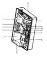
- the drawing shows in each case oblique views of a motor-controlled pivot drive according to the present invention.
- the pivot drive is provided in a housing 10.
- a motor 1 generates a driving force, which is transmitted via a transmission device 3, 4 to a linear movement device 5, 6.
- the driving force of the engine 1 generated by the engine is transmitted via a transaxial drive 2 to a transmission 3 and then to a toothed belt drive 4 in communication with this transmission 3.
- the motor 1 may be small and light, so that there is not much room for it to be provided in the housing 10.
- the linear movement device 5, 6 is formed from a ball screw 5 driven in rotation by the toothed belt drive 4 and a ball screw nut 6 running on this.
- the caused by the rotationally driven ball screw 5 linear movement of the running on this ball screw nut 6 is then via a rocker 7, which is rotatably mounted at its one end to the ball screw nut 6, in a predetermined rotational movement of a rocker 7 mounted on the pivoting device 7A.
- the rotational movement which takes place in particular over an angle of substantially 90 °, is effected by the rocker 7 having in its longitudinal direction a guide opening for guiding the rocker 7 about a hub 9 mounted in the housing 10.
- This hub 9 is mounted in the housing 10 in a receptacle.
- the hub 9 for the connection of a spindle to be actuated by the rotary actuator rotary fitting on a toothing, which preferably has eight teeth.
- a position detection device 8A, 8B is provided, which are designed here as respective electrical contact switches on the left end and on the right end of the ball screw 5. These ends represent respective end positions of the linear movement of the ball screw nut 6 running on the ball screw 5, which contacts the contact switch upon reaching an end position, thereby causing a reversal of direction of the linear movement becomes.
- the ball screw nut 6 is seen at the center position of the ball screw 5, in which none of the contact switches 8A, 8B is contacted.
- a pivoting device 7A is shown as being plate-shaped as a compactly bolted rocker housing and communicating with the hub 9.
- the pivoting device 7A is provided with guide rollers, with which the pivoting device 7A is guided at a movement of the rocker 7 caused by the linear movement device 5, 6 on the outside of the rocker 7.
- a connecting piece of the hub 9 for connection of the pivoting means 7A, 7B is provided with a valve to be actuated by the pivot drive.
- a box 12 is still provided for electronics, which is required for the operation and control of the rotary actuator.
- the electronics are required to effect the reversal of direction caused by the position detection device 8A, 8B.
- the motor-controlled rotary actuator according to the invention is compact and simple and can be operated in a simple manner.
- the motor-controlled rotary actuator is particularly preferably suitable for a closing force of up to 400 Nm.
- the engine can be small and compact.
- the rotary actuator is used in particular for actuating flaps and ball valves.
Landscapes
- Engineering & Computer Science (AREA)
- General Engineering & Computer Science (AREA)
- Mechanical Engineering (AREA)
- Transmission Devices (AREA)
- Valve Device For Special Equipments (AREA)
- Valve-Gear Or Valve Arrangements (AREA)
Description
- Die Erfindung betrifft einen motorgesteuerten Schwenkantrieb mit den Merkmalen des Oberbegriffs des Anspruchs 1.
- Es sind viele Arten von Schwenkantrieben bekannt (
US 3,651,711 undUS 4,085,624 ). Beispielsweise gibt es Schwenkantriebe, die zum Betätigen von Klappen und Kugelhähnen eingesetzt werden. Solche Schwenkantriebe können beispielsweise hydraulisch oder mittels eines Elektromotors gesteuert werden. Ein Beispiel zeigt das DokumentDE 3615368 A1 , welches alle Merkmale des Oberbegriffs des Anspruchs 1 beinhaltet. - Es ist eine Aufgabe der Erfindung, einen kompakt aufgebauten motorgesteuerten Schwenkantrieb zur Verfügung zu stellen.
- Diese Aufgabe wird erfindungsgemäß durch den im Anspruch 1 angegebene Schwenkantrieb gelöst. Die abhängigen Ansprüche 2 bis 12 zeigen spezielle Ausführungsformen des Schwenkantriebs gemäß Anspruch 1.
- Der erfindungsgemäße Schwenkantrieb ist in einem Gehäuse vorgesehen und weist einen Motor auf, der eine Antriebskraft erzeugt, die über eine Getriebeeinrichtung zu einer durch den Schwenkantrieb zu betätigenden Armatur zugeführt wird. Insbesondere wird die Antriebskraft über eine Getriebeeinrichtung zu einer Linearbewegungseinrichtung übertragen, deren lineare Bewegung über eine Schwinge in eine vorbestimmte Drehbewegung einer an der Schwinge gelagerten Schwenkeinrichtung umgewandelt wird. Die Schwenkeinrichtung steht dabei mit der Nabe in Verbindung, ist als kompakt verschraubtes Schwingengehäuse ausgebildet und ist mit Führungsrollen versehen, mit welchen die Schwenkeinrichtung bei einer Bewegung der Schwinge an deren Äußeren geführt wird.
- Der erfindungsgemäße motorgesteuerte Schwenkantrieb ist einfach und kompakt aufgebaut.
- Die vorbestimmte Drehbewegung der Schwenkeinrichtung erfolgt vorzugsweise über einen Winkel von im Wesentlichen 90°.
- Die Getriebeeinrichtung weist vorzugsweise ein mit dem Motor über einen Transaxialantrieb in Verbindung stehendes Getriebe und ein mit diesem in Verbindung stehenden Zahnflachriemenantrieb auf.
- Die Linearbewegungseinrichtung weist vorzugsweise eine durch den Zahnflachriemenantrieb drehend angetriebene Kugelrollspindel und eine auf dieser laufende Kugelgewindemutter auf.
- Die Schwinge ist vorzugsweise an ihrem einen Ende drehbar an der Kugelgewindemutter gelagert und weist weiterhin in ihrer Längsrichtung eine Führungsöffnung zur Führung der Schwinge um eine im Gehäuse angebrachte Nabe auf. Die Nabe ist insbesondere im Gehäuse fest in einer Aufnahme angebracht. Die Nabe weist vorzugsweise eine Verzahnung auf. Vorzugsweise hat diese Verzahnung acht Zähne.
- Die Übertragung der vom Motor erzeugten Antriebskraft bis zur Schwenkeinrichtung erfolgt auf besonders einfache Weise und die Getriebeeinrichtung, die Linearbewegungseinrichtung und die Schwinge benötigen wenig Platz im Gehäuse.
- Vorzugsweise ist eine Positionserfassungseinrichtung vorgesehen, die Endpositionen der Linearbewegungseinrichtung erfasst und eine Richtungsumkehr der linearen Bewegung veranlasst. Dabei weist die Positionserfassungseinrichtung insbesondere einen elektrischen.Kontaktschalter auf. Weiterhin ist vorzugsweise ein Anschlussstück der Nabe zur Verbindung der Schwenkeinrichtung mit einer durch den Schwenkantrieb zu betätigenden Armatur vorgesehen.
- Des weiteren ist vorzugsweise im Gehäuse noch ein Kasten für die zur Betätigung und Steuerung des Schwenkantriebs erforderliche Elektronik vorgesehen.
- Die angegebenen und weitere Merkmale und Einzelheiten der Erfindung ergeben sich aus der folgenden detaillierten Beschreibung und der beigefügten Zeichnung, die Merkmale der vorliegenden Erfindung anhand eines Beispiels darstellt, wobei die Zeichnung eine Schrägansicht eines motorgesteuerten Schwenkantriebs zeigt.
- Im folgenden wird die vorliegende Erfindung anhand einer bevorzugten Ausführungsform unter Bezugnahme auf die beigefügte Zeichnung detailliert erklärt.
- Die Zeichnung zeigt jeweils Schrägansichten eines motorgesteuerten Schwenkantriebs gemäß der vorliegenden Erfindung. Der Schwenkantrieb ist in einem Gehäuse 10 vorgesehen. Dabei erzeugt ein Motor 1 eine Antriebskraft, die über eine Getriebeeinrichtung 3, 4 zu einer Linearbewegungseinrichtung 5, 6 übertragen wird. Insbesondere wird die vom Motor erzeugte Antriebskraft des Motors 1 über einen Transaxialantrieb 2 zu einem Getriebe 3 und dann zu einem mit diesem Getriebe 3 in Verbindung stehenden Zahnflachriemenantrieb 4 übertragen. Der Motor 1 kann insbesondere klein und leicht sein, so dass für ihn im Gehäuse 10 nicht viel Platz vorgesehen werden muss.
- Die Linearbewegungseinrichtung 5, 6 ist aus einer durch den Zahnflachriemenantrieb 4 drehend angetriebenen Kugelrollspindel 5 und einer auf dieser laufenden Kugelgewindemutter 6 ausgebildet. Die durch die drehend angetriebene Kugelrollspindel 5 verursachte lineare Bewegung der auf dieser laufenden Kugelgewindemutter 6 wird dann über eine Schwinge 7, die an ihrem einen Ende drehbar an der Kugelgewindemutter 6 gelagert ist, in eine vorbestimmte Drehbewegung einer an der Schwinge 7 gelagerten Schwenkeinrichtung 7A.
- Die Drehbewegung, die insbesondere über einen Winkel von im Wesentlichen 90° erfolgt, wird dadurch bewirkt, dass die Schwinge 7 in ihrer Längsrichtung eine Führungsöffnung zur Führung der Schwinge 7 um eine im Gehäuse 10 angebrachte Nabe 9 aufweist. Diese Nabe 9 ist im Gehäuse 10 in einer Aufnahme angebracht. Dabei weist die Nabe 9 für den Anschluss einer Spindel einer durch den Schwenkantrieb zu betätigenden Dreharmatur eine Verzahnung auf, die vorzugsweise acht Zähne hat.
- Weiterhin ist eine Positionserfassungseinrichtung 8A, 8B vorgesehen, die hier als jeweilige elektrische Kontaktschalter am linken Ende und am rechten Ende der Kugelrollspindel 5 ausgebildet sind. Diese Enden stellen jeweilige Endpositionen der linearen Bewegung der auf der Kugelrollspindel 5 laufenden Kugelgewindemutter 6 dar, die den Kontaktschalter beim Erreichen einer Endposition kontaktiert, wodurch dann eine Richtungsumkehr der linearen Bewegung veranlasst wird. In der Zeichnung ist die Kugelgewindemutter 6 bei der Mittenposition der Kugelrollspindel 5 zu sehen, bei welcher keiner der Kontaktschalter 8A, 8B kontaktiert wird.
- In der Zeichnung ist als erste bevorzugte Ausführungsform eine Schwenkeinrichtung 7A derart gezeigt, dass sie plattenförmig als kompakt verschraubtes Schwingengehäuse ausgebildet ist und mit der Nabe 9 in Verbindung steht. Die Schwenkeinrichtung 7A ist mit Führungsrollen versehen, mit welchen die Schwenkeinrichtung 7A bei einer durch die Linearbewegungseinrichtung 5, 6 veranlasste Bewegung der Schwinge 7 am Äußeren der Schwinge 7 geführt wird.
- In der Zeichnung ist ein Anschlussstück der Nabe 9 zur Verbindung der Schwenkeinrichtung 7A, 7B mit einer durch den Schwenkantrieb zu betätigenden Armatur vorgesehen.
- Weiterhin ist im Gehäuse 10 des erfindungsgemäßen Schwenkantriebs noch ein Kasten 12 für Elektronik vorgesehen, die für die Betätigung und Steuerung des Schwenkantriebs erforderlich ist. Die Elektronik ist unter anderem dafür nötig, die durch die Positionserfassungseinrichtung 8A, 8B veranlasste Richtungsumkehr zu bewirken.
- Der erfindungsgemäße motorgesteuerte Schwenkantrieb ist kompakt und einfach aufgebaut und kann auf einfache Weise bedient werden. Der motorgesteuerte Schwenkantrieb ist besonderes bevorzugt für eine Schließkraft von bis zu 400 Nm geeignet. Der Motor kann klein und kompakt sein. Der Schwenkantrieb wird insbesondere zur Betätigung von Klappen und Kugelhähnen eingesetzt.
Claims (12)
- Schwenkantrieb in einem Gehäuse (10) mit einem Motor (1) zum Erzeugen einer Antriebskraft, die über eine Getriebeeinrichtung (3, 4) zu einer Linearbewegungseinrichtung (5, 6) übertragen wird, deren lineare Bewegung über eine Schwinge (7) in eine vorbestimmte Drehbewegung einer an der Schwinge (7) gelagerten Schwenkeinrichtung (7A) umgewandelt wird, dadurch gekennzeichnet, dass die Schwenkeinrichtung (7A) mit einer im Gehäuse (10) angebrachten Nabe (9) in Verbindung steht, als kompakt verschraubtes Schwingengehäuse ausgebildet ist und mit Führungsrollen versehen ist, mit welchen die Schwenkeinrichtung (7A) bei einer Bewegung der Schwinge (7) an deren Äußeren geführt wird.
- Schwenkantrieb nach Anspruch 1, dadurch gekennzeichnet, dass die vorbestimmte Drehbewegung über einen Winkel von im Wesentlichen 90° erfolgt.
- Schwenkantrieb nach Anspruch 1 oder 2, dadurch gekennzeichnet, dass die Getriebeeinrichtung (3, 4) ein mit dem Motor (1) über einen Transaxialantrieb (2) in Verbindung stehendes Getriebe (3) und ein mit diesem in Verbindung stehenden Zahnflachriemenantrieb (4) aufweist.
- Schwenkantrieb nach einem der vorhergehenden Ansprüche, dadurch gekennzeichnet, dass die Linearbewegungseinrichtung (5, 6) eine durch den Zahnflachriemenantrieb (4) drehend angetriebene Kugelrollspindel (5) und eine auf dieser laufende Kugelgewindemutter (6) aufweist.
- Schwenkantrieb nach Anspruch 4, dadurch gekennzeichnet, dass die Schwinge (7) an ihrem einen Ende drehbar an der Kugelgewindemutter (6) gelagert ist und in ihrer Längsrichtung eine Führungsöffnung zur Führung der Schwinge (7) um die Nabe (9) aufweist.
- Schwenkantrieb nach Anspruch 5, dadurch gekennzeichnet, dass die Nabe (9) im Gehäuse (10) in einer Aufnahme angebracht ist.
- Schwenkantrieb nach Anspruch 6, dadurch gekennzeichnet, dass die Nabe (9) eine Verzahnung aufweist.
- Schwenkantrieb nach Anspruch 7, dadurch gekennzeichnet, dass die Verzahnung acht Zähne aufweist.
- Schwenkantrieb nach einem der vorangehenden Ansprüche, dadurch gekennzeichnet, dass eine Positionserfassungseinrichtung (8A, 8B) vorgesehen ist, die Endpositionen der Linearbewegungseinrichtung (5, 6) erfasst und eine Richtungsumkehr der linearen Bewegung veranlasst.
- Schwenkantrieb nach Anspruch 9, dadurch gekennzeichnet, dass die Positionserfassungseinrichtung (8A, 8B) einen elektrischen Kontaktschalter aufweist.
- Schwenkantrieb nach einem der Ansprüche 5 bis 10, dadurch gekennzeichnet, dass ein Anschlussstück der Nabe (9) zur Verbindung der Schwenkeinrichtung (7A) mit einer durch den Schwenkantrieb zu betätigenden Armatur vorgesehen ist.
- Schwenkantrieb nach einem der vorhergehenden Ansprüche, wobei im Gehäuse (10) ein Kasten (12) für die erforderliche Elektronik vorgesehen ist.
Applications Claiming Priority (1)
| Application Number | Priority Date | Filing Date | Title |
|---|---|---|---|
| DE102006043994A DE102006043994A1 (de) | 2006-09-19 | 2006-09-19 | Motorgesteuerter Schwenkantrieb |
Publications (3)
| Publication Number | Publication Date |
|---|---|
| EP1903256A2 EP1903256A2 (de) | 2008-03-26 |
| EP1903256A3 EP1903256A3 (de) | 2009-03-18 |
| EP1903256B1 true EP1903256B1 (de) | 2011-05-18 |
Family
ID=38820274
Family Applications (1)
| Application Number | Title | Priority Date | Filing Date |
|---|---|---|---|
| EP07016844A Active EP1903256B1 (de) | 2006-09-19 | 2007-08-28 | Motorgesteuerter Schwenkantrieb |
Country Status (3)
| Country | Link |
|---|---|
| EP (1) | EP1903256B1 (de) |
| AT (1) | ATE510151T1 (de) |
| DE (1) | DE102006043994A1 (de) |
Cited By (1)
| Publication number | Priority date | Publication date | Assignee | Title |
|---|---|---|---|---|
| CN104676085A (zh) * | 2015-02-02 | 2015-06-03 | 温州合力自动化仪表有限公司 | 具有横向行程的执行器 |
Families Citing this family (3)
| Publication number | Priority date | Publication date | Assignee | Title |
|---|---|---|---|---|
| DE102010005526A1 (de) | 2010-01-23 | 2011-07-28 | FESTO AG & Co. KG, 73734 | Drehantriebsvorrichtung |
| CN105546108B (zh) * | 2015-12-30 | 2020-04-17 | 广州汽车集团股份有限公司 | 线控换挡执行器及线控换挡装置 |
| US11614180B2 (en) * | 2019-12-27 | 2023-03-28 | Takatori Seisakusho Co., Ltd. | Valve actuator |
Family Cites Families (3)
| Publication number | Priority date | Publication date | Assignee | Title |
|---|---|---|---|---|
| US3651711A (en) * | 1970-04-16 | 1972-03-28 | Anderson Greenwood & Co | Shaft rotating device |
| US4085624A (en) * | 1976-03-24 | 1978-04-25 | Kitazawa Shoji Kabushiki Kaisha | Electrically driven actuator |
| DE8612452U1 (de) * | 1986-05-06 | 1986-06-26 | Müller, Fritz, 7118 Ingelfingen | Elektromotorisch angetriebene Schwenkvorrichtung |
-
2006
- 2006-09-19 DE DE102006043994A patent/DE102006043994A1/de not_active Withdrawn
-
2007
- 2007-08-28 EP EP07016844A patent/EP1903256B1/de active Active
- 2007-08-28 AT AT07016844T patent/ATE510151T1/de active
Cited By (2)
| Publication number | Priority date | Publication date | Assignee | Title |
|---|---|---|---|---|
| CN104676085A (zh) * | 2015-02-02 | 2015-06-03 | 温州合力自动化仪表有限公司 | 具有横向行程的执行器 |
| CN104676085B (zh) * | 2015-02-02 | 2017-05-31 | 温州合力自动化仪表有限公司 | 具有横向行程的执行器 |
Also Published As
| Publication number | Publication date |
|---|---|
| ATE510151T1 (de) | 2011-06-15 |
| EP1903256A2 (de) | 2008-03-26 |
| EP1903256A3 (de) | 2009-03-18 |
| DE102006043994A1 (de) | 2008-03-27 |
Similar Documents
| Publication | Publication Date | Title |
|---|---|---|
| DE102015104111A1 (de) | Antriebsmechanismus mit Doppelschneckengetriebe | |
| DE3540652C2 (de) | Elektrischer Schraubendreher | |
| DE10117934A1 (de) | Antrieb mit einem Motor und mit mindestens einem dem Motor nachgeschalteten Getriebe | |
| EP0141046A2 (de) | Ventileinrichtung mit einer fernsteuerbaren Betätigungseinrichtung | |
| EP1233690A1 (de) | Elektromotorischer stellantrieb | |
| DE19819421A1 (de) | Schiebetürantrieb für die Schiebetür eines Kraftfahrzeuges | |
| EP3718446B1 (de) | Einstelleinrichtung zum einstellen des mahlgrads eines mahlwerks | |
| WO2007137670A1 (de) | Türantrieb mit während der türbewegung veränderbarer federvorspannung | |
| EP2411251B1 (de) | Elektromotorischer hilfsantrieb, insbesondere wischerantrieb | |
| DE2825355A1 (de) | Einrichtung zur elektromotorischen zentralverriegelung von kraftfahrzeugen | |
| DE102023102659A1 (de) | Digitale Automatische Kupplung (DAK) mit elektromechanischem Aktuator für ein Schienenfahrzeug und Schienenfahrzeug mit einer solchen Kupplung | |
| DE3615368C2 (de) | Elektromotorisch angetriebene Schwenkvorrichtung | |
| EP1903256A2 (de) | Motorgesteuerter Schwenkantrieb | |
| DE20213364U1 (de) | Antriebsvorrichtung | |
| DE102015112685B3 (de) | Antrieb zum Bewegen eines Flügels | |
| DE19948265A1 (de) | Linearstellglied | |
| DE102005015451A1 (de) | Elektromechanische Servolenkung | |
| DE10254125B4 (de) | Elektromotorischer Möbelantrieb zum Verstellen von Teilen eines Möbels relativ zueinander | |
| EP1089019A1 (de) | Linearstellglied | |
| DE19532590A1 (de) | Motor- und handbetätigbarer Stellantrieb | |
| EP1201370B1 (de) | Elektrisch betätigbare Werkstück-Spannvorrichtung | |
| EP4010555B1 (de) | Schiebetürantrieb für ein kraftfahrzeug | |
| DE19617226C2 (de) | Abschaltvorrichtung für den Antrieb eines zwischen Endstellungen verstellbaren Teils eines Fahrzeuges | |
| DE10354594B4 (de) | Antriebseinheit eines Schaltgerätes einer gasisolierten Schaltanlage und Baukastensystem zur Bildung einer Antriebseinheit | |
| EP1564443B1 (de) | Ausrückbarer Reibradspanner |
Legal Events
| Date | Code | Title | Description |
|---|---|---|---|
| PUAI | Public reference made under article 153(3) epc to a published international application that has entered the european phase |
Free format text: ORIGINAL CODE: 0009012 |
|
| AK | Designated contracting states |
Kind code of ref document: A2 Designated state(s): AT BE BG CH CY CZ DE DK EE ES FI FR GB GR HU IE IS IT LI LT LU LV MC MT NL PL PT RO SE SI SK TR |
|
| AX | Request for extension of the european patent |
Extension state: AL BA HR MK YU |
|
| PUAL | Search report despatched |
Free format text: ORIGINAL CODE: 0009013 |
|
| AK | Designated contracting states |
Kind code of ref document: A3 Designated state(s): AT BE BG CH CY CZ DE DK EE ES FI FR GB GR HU IE IS IT LI LT LU LV MC MT NL PL PT RO SE SI SK TR |
|
| AX | Request for extension of the european patent |
Extension state: AL BA HR MK RS |
|
| 17P | Request for examination filed |
Effective date: 20090630 |
|
| AKX | Designation fees paid |
Designated state(s): AT BE BG CH CY CZ DE DK EE ES FI FR GB GR HU IE IS IT LI LT LU LV MC MT NL PL PT RO SE SI SK TR |
|
| GRAP | Despatch of communication of intention to grant a patent |
Free format text: ORIGINAL CODE: EPIDOSNIGR1 |
|
| GRAS | Grant fee paid |
Free format text: ORIGINAL CODE: EPIDOSNIGR3 |
|
| GRAA | (expected) grant |
Free format text: ORIGINAL CODE: 0009210 |
|
| REG | Reference to a national code |
Ref country code: GB Ref legal event code: FG4D Free format text: NOT ENGLISH |
|
| REG | Reference to a national code |
Ref country code: CH Ref legal event code: EP Ref country code: CH Ref legal event code: NV Representative=s name: ROTTMANN, ZIMMERMANN + PARTNER AG |
|
| REG | Reference to a national code |
Ref country code: IE Ref legal event code: FG4D Free format text: LANGUAGE OF EP DOCUMENT: GERMAN |
|
| REG | Reference to a national code |
Ref country code: DE Ref legal event code: R096 Ref document number: 502007007225 Country of ref document: DE Effective date: 20110630 |
|
| REG | Reference to a national code |
Ref country code: NL Ref legal event code: VDEP Effective date: 20110518 |
|
| REG | Reference to a national code |
Ref country code: CH Ref legal event code: PFA Owner name: GEMUE GEBRUEDER MUELLER APPARATEBAU GMBH & CO. KG Free format text: GEMUE GEBRUEDER MUELLER APPARATEBAU GMBH & CO. KG#FRITZ-MUELLER-STRASSE 6-8#74653 INGELFINGEN (DE) -TRANSFER TO- GEMUE GEBRUEDER MUELLER APPARATEBAU GMBH & CO. KG#FRITZ-MUELLER-STRASSE 6-8#74653 INGELFINGEN (DE) |
|
| PG25 | Lapsed in a contracting state [announced via postgrant information from national office to epo] |
Ref country code: PT Free format text: LAPSE BECAUSE OF FAILURE TO SUBMIT A TRANSLATION OF THE DESCRIPTION OR TO PAY THE FEE WITHIN THE PRESCRIBED TIME-LIMIT Effective date: 20110919 Ref country code: SE Free format text: LAPSE BECAUSE OF FAILURE TO SUBMIT A TRANSLATION OF THE DESCRIPTION OR TO PAY THE FEE WITHIN THE PRESCRIBED TIME-LIMIT Effective date: 20110518 Ref country code: LT Free format text: LAPSE BECAUSE OF FAILURE TO SUBMIT A TRANSLATION OF THE DESCRIPTION OR TO PAY THE FEE WITHIN THE PRESCRIBED TIME-LIMIT Effective date: 20110518 |
|
| PG25 | Lapsed in a contracting state [announced via postgrant information from national office to epo] |
Ref country code: GR Free format text: LAPSE BECAUSE OF FAILURE TO SUBMIT A TRANSLATION OF THE DESCRIPTION OR TO PAY THE FEE WITHIN THE PRESCRIBED TIME-LIMIT Effective date: 20110819 Ref country code: IS Free format text: LAPSE BECAUSE OF FAILURE TO SUBMIT A TRANSLATION OF THE DESCRIPTION OR TO PAY THE FEE WITHIN THE PRESCRIBED TIME-LIMIT Effective date: 20110918 Ref country code: LV Free format text: LAPSE BECAUSE OF FAILURE TO SUBMIT A TRANSLATION OF THE DESCRIPTION OR TO PAY THE FEE WITHIN THE PRESCRIBED TIME-LIMIT Effective date: 20110518 Ref country code: FI Free format text: LAPSE BECAUSE OF FAILURE TO SUBMIT A TRANSLATION OF THE DESCRIPTION OR TO PAY THE FEE WITHIN THE PRESCRIBED TIME-LIMIT Effective date: 20110518 Ref country code: ES Free format text: LAPSE BECAUSE OF FAILURE TO SUBMIT A TRANSLATION OF THE DESCRIPTION OR TO PAY THE FEE WITHIN THE PRESCRIBED TIME-LIMIT Effective date: 20110829 Ref country code: SI Free format text: LAPSE BECAUSE OF FAILURE TO SUBMIT A TRANSLATION OF THE DESCRIPTION OR TO PAY THE FEE WITHIN THE PRESCRIBED TIME-LIMIT Effective date: 20110518 Ref country code: CY Free format text: LAPSE BECAUSE OF FAILURE TO SUBMIT A TRANSLATION OF THE DESCRIPTION OR TO PAY THE FEE WITHIN THE PRESCRIBED TIME-LIMIT Effective date: 20110518 |
|
| REG | Reference to a national code |
Ref country code: IE Ref legal event code: FD4D |
|
| PG25 | Lapsed in a contracting state [announced via postgrant information from national office to epo] |
Ref country code: MT Free format text: LAPSE BECAUSE OF FAILURE TO SUBMIT A TRANSLATION OF THE DESCRIPTION OR TO PAY THE FEE WITHIN THE PRESCRIBED TIME-LIMIT Effective date: 20110518 Ref country code: NL Free format text: LAPSE BECAUSE OF FAILURE TO SUBMIT A TRANSLATION OF THE DESCRIPTION OR TO PAY THE FEE WITHIN THE PRESCRIBED TIME-LIMIT Effective date: 20110518 |
|
| PG25 | Lapsed in a contracting state [announced via postgrant information from national office to epo] |
Ref country code: CZ Free format text: LAPSE BECAUSE OF FAILURE TO SUBMIT A TRANSLATION OF THE DESCRIPTION OR TO PAY THE FEE WITHIN THE PRESCRIBED TIME-LIMIT Effective date: 20110518 Ref country code: IE Free format text: LAPSE BECAUSE OF FAILURE TO SUBMIT A TRANSLATION OF THE DESCRIPTION OR TO PAY THE FEE WITHIN THE PRESCRIBED TIME-LIMIT Effective date: 20110518 Ref country code: EE Free format text: LAPSE BECAUSE OF FAILURE TO SUBMIT A TRANSLATION OF THE DESCRIPTION OR TO PAY THE FEE WITHIN THE PRESCRIBED TIME-LIMIT Effective date: 20110518 |
|
| BERE | Be: lapsed |
Owner name: GEMU GEBRUDER MULLER APPARATEBAU G.M.B.H. & CO. KG Effective date: 20110831 |
|
| PG25 | Lapsed in a contracting state [announced via postgrant information from national office to epo] |
Ref country code: RO Free format text: LAPSE BECAUSE OF FAILURE TO SUBMIT A TRANSLATION OF THE DESCRIPTION OR TO PAY THE FEE WITHIN THE PRESCRIBED TIME-LIMIT Effective date: 20110518 Ref country code: SK Free format text: LAPSE BECAUSE OF FAILURE TO SUBMIT A TRANSLATION OF THE DESCRIPTION OR TO PAY THE FEE WITHIN THE PRESCRIBED TIME-LIMIT Effective date: 20110518 Ref country code: PL Free format text: LAPSE BECAUSE OF FAILURE TO SUBMIT A TRANSLATION OF THE DESCRIPTION OR TO PAY THE FEE WITHIN THE PRESCRIBED TIME-LIMIT Effective date: 20110518 Ref country code: DK Free format text: LAPSE BECAUSE OF FAILURE TO SUBMIT A TRANSLATION OF THE DESCRIPTION OR TO PAY THE FEE WITHIN THE PRESCRIBED TIME-LIMIT Effective date: 20110518 |
|
| PLBE | No opposition filed within time limit |
Free format text: ORIGINAL CODE: 0009261 |
|
| STAA | Information on the status of an ep patent application or granted ep patent |
Free format text: STATUS: NO OPPOSITION FILED WITHIN TIME LIMIT |
|
| PG25 | Lapsed in a contracting state [announced via postgrant information from national office to epo] |
Ref country code: MC Free format text: LAPSE BECAUSE OF NON-PAYMENT OF DUE FEES Effective date: 20110831 |
|
| 26N | No opposition filed |
Effective date: 20120221 |
|
| PG25 | Lapsed in a contracting state [announced via postgrant information from national office to epo] |
Ref country code: BE Free format text: LAPSE BECAUSE OF NON-PAYMENT OF DUE FEES Effective date: 20110831 |
|
| REG | Reference to a national code |
Ref country code: DE Ref legal event code: R097 Ref document number: 502007007225 Country of ref document: DE Effective date: 20120221 |
|
| PG25 | Lapsed in a contracting state [announced via postgrant information from national office to epo] |
Ref country code: LU Free format text: LAPSE BECAUSE OF NON-PAYMENT OF DUE FEES Effective date: 20110828 |
|
| PG25 | Lapsed in a contracting state [announced via postgrant information from national office to epo] |
Ref country code: BG Free format text: LAPSE BECAUSE OF FAILURE TO SUBMIT A TRANSLATION OF THE DESCRIPTION OR TO PAY THE FEE WITHIN THE PRESCRIBED TIME-LIMIT Effective date: 20110818 |
|
| PG25 | Lapsed in a contracting state [announced via postgrant information from national office to epo] |
Ref country code: TR Free format text: LAPSE BECAUSE OF FAILURE TO SUBMIT A TRANSLATION OF THE DESCRIPTION OR TO PAY THE FEE WITHIN THE PRESCRIBED TIME-LIMIT Effective date: 20110518 |
|
| PG25 | Lapsed in a contracting state [announced via postgrant information from national office to epo] |
Ref country code: HU Free format text: LAPSE BECAUSE OF FAILURE TO SUBMIT A TRANSLATION OF THE DESCRIPTION OR TO PAY THE FEE WITHIN THE PRESCRIBED TIME-LIMIT Effective date: 20110518 |
|
| PGFP | Annual fee paid to national office [announced via postgrant information from national office to epo] |
Ref country code: GB Payment date: 20140729 Year of fee payment: 8 |
|
| REG | Reference to a national code |
Ref country code: FR Ref legal event code: PLFP Year of fee payment: 9 |
|
| PGFP | Annual fee paid to national office [announced via postgrant information from national office to epo] |
Ref country code: AT Payment date: 20150820 Year of fee payment: 9 Ref country code: FR Payment date: 20150824 Year of fee payment: 9 |
|
| PGFP | Annual fee paid to national office [announced via postgrant information from national office to epo] |
Ref country code: IT Payment date: 20150827 Year of fee payment: 9 |
|
| GBPC | Gb: european patent ceased through non-payment of renewal fee |
Effective date: 20150828 |
|
| PG25 | Lapsed in a contracting state [announced via postgrant information from national office to epo] |
Ref country code: GB Free format text: LAPSE BECAUSE OF NON-PAYMENT OF DUE FEES Effective date: 20150828 |
|
| REG | Reference to a national code |
Ref country code: CH Ref legal event code: PCAR Free format text: NEW ADDRESS: GARTENSTRASSE 28 A, 5400 BADEN (CH) |
|
| REG | Reference to a national code |
Ref country code: AT Ref legal event code: MM01 Ref document number: 510151 Country of ref document: AT Kind code of ref document: T Effective date: 20160828 |
|
| REG | Reference to a national code |
Ref country code: FR Ref legal event code: ST Effective date: 20170428 |
|
| PG25 | Lapsed in a contracting state [announced via postgrant information from national office to epo] |
Ref country code: AT Free format text: LAPSE BECAUSE OF NON-PAYMENT OF DUE FEES Effective date: 20160828 |
|
| PG25 | Lapsed in a contracting state [announced via postgrant information from national office to epo] |
Ref country code: FR Free format text: LAPSE BECAUSE OF NON-PAYMENT OF DUE FEES Effective date: 20160831 |
|
| PG25 | Lapsed in a contracting state [announced via postgrant information from national office to epo] |
Ref country code: IT Free format text: LAPSE BECAUSE OF NON-PAYMENT OF DUE FEES Effective date: 20160828 |
|
| PGFP | Annual fee paid to national office [announced via postgrant information from national office to epo] |
Ref country code: CH Payment date: 20190924 Year of fee payment: 13 |
|
| REG | Reference to a national code |
Ref country code: CH Ref legal event code: PL |
|
| PG25 | Lapsed in a contracting state [announced via postgrant information from national office to epo] |
Ref country code: CH Free format text: LAPSE BECAUSE OF NON-PAYMENT OF DUE FEES Effective date: 20200831 Ref country code: LI Free format text: LAPSE BECAUSE OF NON-PAYMENT OF DUE FEES Effective date: 20200831 |
|
| P01 | Opt-out of the competence of the unified patent court (upc) registered |
Effective date: 20230524 |
|
| PGFP | Annual fee paid to national office [announced via postgrant information from national office to epo] |
Ref country code: DE Payment date: 20251021 Year of fee payment: 19 |