EP1903326A2 - Dispositif destiné à la détermination de moments de torsion inférieurs au micro-Newton-mètre - Google Patents
Dispositif destiné à la détermination de moments de torsion inférieurs au micro-Newton-mètre Download PDFInfo
- Publication number
- EP1903326A2 EP1903326A2 EP07016696A EP07016696A EP1903326A2 EP 1903326 A2 EP1903326 A2 EP 1903326A2 EP 07016696 A EP07016696 A EP 07016696A EP 07016696 A EP07016696 A EP 07016696A EP 1903326 A2 EP1903326 A2 EP 1903326A2
- Authority
- EP
- European Patent Office
- Prior art keywords
- clamping
- component
- measuring part
- fiber
- torque
- Prior art date
- Legal status (The legal status is an assumption and is not a legal conclusion. Google has not performed a legal analysis and makes no representation as to the accuracy of the status listed.)
- Granted
Links
Images


Classifications
-
- G—PHYSICS
- G01—MEASURING; TESTING
- G01N—INVESTIGATING OR ANALYSING MATERIALS BY DETERMINING THEIR CHEMICAL OR PHYSICAL PROPERTIES
- G01N3/00—Investigating strength properties of solid materials by application of mechanical stress
- G01N3/22—Investigating strength properties of solid materials by application of mechanical stress by applying steady torsional forces
-
- G—PHYSICS
- G01—MEASURING; TESTING
- G01N—INVESTIGATING OR ANALYSING MATERIALS BY DETERMINING THEIR CHEMICAL OR PHYSICAL PROPERTIES
- G01N3/00—Investigating strength properties of solid materials by application of mechanical stress
- G01N3/32—Investigating strength properties of solid materials by application of mechanical stress by applying repeated or pulsating forces
-
- G—PHYSICS
- G01—MEASURING; TESTING
- G01N—INVESTIGATING OR ANALYSING MATERIALS BY DETERMINING THEIR CHEMICAL OR PHYSICAL PROPERTIES
- G01N2203/00—Investigating strength properties of solid materials by application of mechanical stress
- G01N2203/0014—Type of force applied
- G01N2203/0021—Torsional
-
- G—PHYSICS
- G01—MEASURING; TESTING
- G01N—INVESTIGATING OR ANALYSING MATERIALS BY DETERMINING THEIR CHEMICAL OR PHYSICAL PROPERTIES
- G01N2203/00—Investigating strength properties of solid materials by application of mechanical stress
- G01N2203/003—Generation of the force
- G01N2203/0032—Generation of the force using mechanical means
-
- G—PHYSICS
- G01—MEASURING; TESTING
- G01N—INVESTIGATING OR ANALYSING MATERIALS BY DETERMINING THEIR CHEMICAL OR PHYSICAL PROPERTIES
- G01N2203/00—Investigating strength properties of solid materials by application of mechanical stress
- G01N2203/02—Details not specific for a particular testing method
- G01N2203/025—Geometry of the test
- G01N2203/0252—Monoaxial, i.e. the forces being applied along a single axis of the specimen
-
- G—PHYSICS
- G01—MEASURING; TESTING
- G01N—INVESTIGATING OR ANALYSING MATERIALS BY DETERMINING THEIR CHEMICAL OR PHYSICAL PROPERTIES
- G01N2203/00—Investigating strength properties of solid materials by application of mechanical stress
- G01N2203/02—Details not specific for a particular testing method
- G01N2203/026—Specifications of the specimen
- G01N2203/0262—Shape of the specimen
- G01N2203/0278—Thin specimens
- G01N2203/028—One dimensional, e.g. filaments, wires, ropes or cables
-
- G—PHYSICS
- G01—MEASURING; TESTING
- G01N—INVESTIGATING OR ANALYSING MATERIALS BY DETERMINING THEIR CHEMICAL OR PHYSICAL PROPERTIES
- G01N2203/00—Investigating strength properties of solid materials by application of mechanical stress
- G01N2203/02—Details not specific for a particular testing method
- G01N2203/04—Chucks, fixtures, jaws, holders or anvils
- G01N2203/0429—Chucks, fixtures, jaws, holders or anvils using adhesive bond; Gluing
-
- G—PHYSICS
- G01—MEASURING; TESTING
- G01N—INVESTIGATING OR ANALYSING MATERIALS BY DETERMINING THEIR CHEMICAL OR PHYSICAL PROPERTIES
- G01N2203/00—Investigating strength properties of solid materials by application of mechanical stress
- G01N2203/02—Details not specific for a particular testing method
- G01N2203/06—Indicating or recording means; Sensing means
- G01N2203/0617—Electrical or magnetic indicating, recording or sensing means
- G01N2203/0623—Electrical or magnetic indicating, recording or sensing means using piezoelectric gauges
Definitions
- the invention relates to a device for determining torsional moments in the submicronewtonmeter range in small components, more preferably on individual fibers according to the first patent claim.
- Torsion tests are used to determine torsional hardening curves, from which shear modulus, torsional yield strength, torsional yield strength and torsional strength of a material, a component or a component can be determined.
- the parameters to be determined are reduced to the torsional strength and shear modulus. Torsion tests thus serve to set a reproducibly defined load condition in a sample to be tested, which is not limited to studies on elasto-plastic material behavior.
- the fundamental problem is to provide a suitable experimental technique that allows reliable quantitative statements about the state of stress.
- morphological dimensions in the microstructure such as the grain size or the dislocation structures of the materials used.
- solidification takes place, which is significantly influenced by strain gradients due to uniaxial or multiaxial stresses.
- Torsional tests usually measure the torsion moment and the rotational angle change in the sample caused by the torsional moment.
- Torsionsprüfvorraumen serve to carry out torsion tests.
- a sample preferably a non-tapered round sample
- a geared motor or an attached lever mechanism on the other side of the sample the applied torque is measured.
- torsional testing on fibers only anticipates low torques.
- special transducers are used for the measurement, in which an applied torsional moment acts against one or more spring plates with a linear spring characteristic, and the compliance is measured optically by deflecting a light beam through a rotating mirror. The axial force is not measurable by such a transducer.
- JP 07333126 A a device for optical fibers is disclosed in which a single fiber is clamped in two clamping devices and loaded on train and is thereby twisted by a stepper motor in addition.
- the DE 1 828 549 U discloses a device for the quantitative determination of a torsional moment in elongate samples.
- the device comprises two clamps for the sample, wherein a clamping for applying a torque is driven by an axial motor and the other clamping is equipped with a sensor.
- This sensor comprises a bending stressed rod as a torque arm, wherein the bending of the Stabs represents a measure of the torque.
- the bending can be detected quantitatively via applied strain gauges, alternatively via capacitive or inductive measuring organs.
- a device for determining a torsional moment in fibers wherein the torsional moment is also detected by a strain gauge applied with elastic measuring spring as a torque arm. To detect even small torsional moments but decoupled from the clamping applied directly to the fiber, being supported on both sides of the fiber axially projecting against each a fixed bearing.
- the object of the invention is therefore to provide a device for the experimental determination of the torsional moment in torsion tests in small components, in particular on thin fibers, which allows a measurement of very small torques as possible without the aforementioned limitations due to system-related hysteresis.
- a device for determining torsional moments in the submicronewtonmeter range in components comprises an upper and a lower clamping for the component, preferably a single fiber (eg gold wires with a diameter of 10 to 100 microns), one of the clamping rotatably mounted and preferably driven by a motor for applying a torque to the component.
- the axis of rotation of the one clamping is oriented in the direction of the other clamping and / or preferably indicates the orientation of the clamping.
- the actual torsion measurement is carried out by means of a measuring part, which is firmly placed on the component between the two clamping.
- the measuring part comprises a force acting on a stylus of a force sensor torque arm as fixed on the component part.
- a force acting on a stylus of a force sensor torque arm as fixed on the component part.
- piezoelectric force sensors are used, alternatively, other sensors such as capacitive, ohmic or inductive systems.
- the torque arm is preferably configured with at least two cantilevers projecting at the same angle about the axis of rotation, each of which acts on its own measuring part, ie its own stylus.
- each measuring part detects a force basically independent of other measuring parts.
- Several measuring parts can be interconnected for a torque determination (eg by averaging).
- a device prefferably equips a device with a plurality of measuring parts, which differ from one another in terms of their measuring ranges and / or measuring accuracies in favor of an extended measuring range and / or an increased measuring accuracy in specific torque windows.
- the restraints are integrated in a preferred embodiment in the supports of a material testing machine, preferably a mechanical universal testing machine.
- a material testing machine preferably a mechanical universal testing machine.
- a piezoelectric force sensor with a stylus, such as e.g. used in atomic force microscopes, but also in turntables.
- a measuring means is suitable for the quantitative detection of even the smallest forces, with a bending of the torque arm inherently no longer required for detecting the torque.
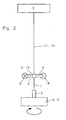
- FIG. 1 The basic principle of the device is shown in FIG. 1 as well as in FIG . 2 schematically.
- the component is in both cases a single fiber 1, which is firmly clamped in an upper and a lower clamping 2 and 3 and is on scholarmaschinen worne support 4 of a universal testing machine, not shown on train loadable.
- the lower support is designed as a turntable 5 , wherein the orientation of the axis of rotation of the clamped single fiber 1 corresponds.
- a rigid crossbar 6 as the aforementioned torque arm with two symmetrical to single fiber cantilevers by preferably (Fig.1) fixed by gluing 7 , both sides and symmetrical to the single fiber on each preferably a piezoelectric force measuring device 8, preferably of the aforementioned type comprises a force sensor with a stylus, acts.
- force sensors for example via micromanipulators finely adjustable (path resolution to 0.5 nm) to the crossbar, preferably convex curved or designed as a guide for styli force introduction surfaces brought.
- a bonding method such as, for example, thermocompression methods (eg ballhead bonding) or ultrasound-supported methods (for example, wedgebonding) is also suitable, wherein the connection should not lead to premature breakage of the fiber.
- the single fiber is divided by the crossbeam into two sections, with only the lower portion between the bond 7 and the lower rotary table-side clamping 3 is twisted by the turntable 5 and forms the measuring section 9 .
- the portion 10 which is arranged at the top in the embodiment is not twisted due to the almost complete lack of rotational displacement between the bond 7 and the upper clamping 2 and serves to transmit tensile forces between the supports 4.
- the outriggers are firmly connected to the clamping, preferably with a soldering or welding connection.
- the cantilevers do not engage directly on the single fiber, but preferably on the restraint or other parts of the device. In this way, possible incorrect loads from the single fiber can be better controlled and eliminated if necessary by eg a guide (eg tension element).
- the upper portion can also be formed in this region by a tension element 11 (see Fig . 2) such as, for example, a fiber having increased strength, in which case the individual fiber to be tested extends only over the lower measurement section 9 extends and the bond 7 serves as a coupling piece 12 .
- a tension element 11 such as, for example, a fiber having increased strength, in which case the individual fiber to be tested extends only over the lower measurement section 9 extends and the bond 7 serves as a coupling piece 12 .
- components such as metallic wires or single fibers, connected via a coupling piece with the component (preferably gebonded or glued) and clamped in a universal testing under a low preload.
- Their signals are amplified to a PC with integrated data acquisition passed there with the associated data (Current angle of rotation) of the turntable linked, so that the respective torsional moments can be determined depending on the current pushing expansions.
- a force sensor is sufficient for torque determination.
- two, as seen in Figures 1 and 2 diagonally opposite equidistantly mounted sensors but a fiber towards advantageous symmetrical arrangement of the device is achieved.
- These cause due to a not symmetrical to the rotation axis power transmission to only one force sensor, so that a lateral deflection of the component of the rotation axis and thus the requirement for a possibility of displacement of the turntable (and the rotation axis) in the xy direction.
- these effects can also be determined by calculation in this arrangement, or be eliminated by averaging several waveforms.
- the force sensors used are preferably so-called AFM (Atomic Force Microscope) tips or cantilevers. Due to the steady development in the field of atomic force microscopy in recent years, today measuring tips are commercially available, which allow easy measurements with resolutions in the nN range. Thus, for example, ductile metallic wires of copper, gold, etc. with a diameter of 10 microns and smaller can be tested in the device. In principle, the feasibility of experiments here is less limited by the sensitivity of the measuring apparatus, but rather by limits to the preparability / manageability of ever thinner samples.
- the components to be tested are glued preferably in the context of the embodiment shown in Figure 1 in stable frame for better handling.
- 3 shows a single fiber 1 in a flat cardboard frame 13 a recess 14 glued bridging in the frame.
- the two adhesive dots 15 serve as clamping for the single fiber.
- the fiber is held with an excess length on both sides of the frame with the protruding ends on this, centered, fixed with the adhesive points and then shortened the protruding ends.
- Serving as a torque arm transverse bar 6 is also shown in Figure 3 in the recess 14 plan laid under or on the frame or inserted between the frame and fiber and also fixed by gluing 7 on the fiber.
- the crossbeam is oriented orthogonally to the fiber and protrudes equally on both sides of the fiber (symmetry).
- Said sample preparation is carried out to ensure the same geometric dimensions, preferably by means of templates in which fiber, crossbeam and cardboard frame are positively guided.
- the adhesive is preferably a cyanacrylate adhesive (superglue). Bonding 7 and adhesive dots 15 extend over the entire of the crossbar 6 or Pappanteil of the cardboard frame 13 adjacent parts of the fiber 1.
- the entire cardboard frame is clamped with the fiber in the restraints of the supports, wherein the Fiber is to use perpendicular to avoid superimposed bending stresses.
- the lateral cardboard webs 16 are separated from the frame, preferably in the entire extension region of the recess 14 , before the force sensors 8 are applied .
- the cardboard frame is first clamped in the upper support by way of example.
- This, as well as the lower support has two jaws with guide gauge for the exact positioning of the cardboard frame.
- the dead weight of the frame is detected by a load cell in the upper support, the force value is set to zero (electronically zeroed).
- a clamping in the lower support possibly with xy-Verfahrtisch for lateral fine adjustment
- the frame is clamped at low pressure load, which bends slightly.
- the calibration of the force measuring devices is preferably carried out as part of a torsion and tensile test on a (preferably highly isotropic) fiber (eg tungsten wire or glass fiber) with known material characteristics (in particular the transverse contraction number ⁇ ).
- a (preferably highly isotropic) fiber eg tungsten wire or glass fiber
- known material characteristics in particular the transverse contraction number ⁇ .
- the calibrated force transducers can then be used to perform torsional tests on different samples and to evaluate them quantitatively.
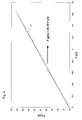
- 5a and b show, by way of example, the determined torsional moments M t in ⁇ Nm from measurements on a plurality of gold wires with a diameter D of 25 ⁇ m (FIG. 12.5 ⁇ m (FIG. 5b) as measured curves 18 as a function of the strain rate ⁇ .
- the position of the measurement curves is at higher rotational speeds, so that even at higher torsional velocities and strain rate changes d ⁇ / dt tends to be higher than the other measurement curves with otherwise identical experimental parameters (see trend direction 19 in FIGS . 5a and b ).
Landscapes
- Physics & Mathematics (AREA)
- Health & Medical Sciences (AREA)
- Life Sciences & Earth Sciences (AREA)
- Chemical & Material Sciences (AREA)
- Analytical Chemistry (AREA)
- Biochemistry (AREA)
- General Health & Medical Sciences (AREA)
- General Physics & Mathematics (AREA)
- Immunology (AREA)
- Pathology (AREA)
- Investigating Strength Of Materials By Application Of Mechanical Stress (AREA)
- Photoreceptors In Electrophotography (AREA)
- Treatment Of Fiber Materials (AREA)
- Preliminary Treatment Of Fibers (AREA)
Applications Claiming Priority (1)
| Application Number | Priority Date | Filing Date | Title |
|---|---|---|---|
| DE102006044522A DE102006044522A1 (de) | 2006-09-23 | 2006-09-23 | Vorrichtung zur Bestimmung von Torsionsmomenten im Submikronewtonmeterbereich |
Publications (3)
| Publication Number | Publication Date |
|---|---|
| EP1903326A2 true EP1903326A2 (fr) | 2008-03-26 |
| EP1903326A3 EP1903326A3 (fr) | 2009-08-19 |
| EP1903326B1 EP1903326B1 (fr) | 2011-01-26 |
Family
ID=38820279
Family Applications (1)
| Application Number | Title | Priority Date | Filing Date |
|---|---|---|---|
| EP07016696A Not-in-force EP1903326B1 (fr) | 2006-09-23 | 2007-08-25 | Dispositif destiné à la détermination de moments de torsion inférieurs au micro-Newton-mètre |
Country Status (3)
| Country | Link |
|---|---|
| EP (1) | EP1903326B1 (fr) |
| AT (1) | ATE497153T1 (fr) |
| DE (2) | DE102006044522A1 (fr) |
Cited By (3)
| Publication number | Priority date | Publication date | Assignee | Title |
|---|---|---|---|---|
| CN110231236A (zh) * | 2019-06-26 | 2019-09-13 | 江苏通光电子线缆股份有限公司 | 电缆抗扭转性能测试设备及测试方法 |
| CN112255129A (zh) * | 2020-10-22 | 2021-01-22 | 江苏理工学院 | 一种血管支架体外扭转加载装置 |
| CN113340499A (zh) * | 2021-05-21 | 2021-09-03 | 中国人民解放军战略支援部队航天工程大学 | 一种基于凸轮转角测量的微小推力测量装置 |
Families Citing this family (1)
| Publication number | Priority date | Publication date | Assignee | Title |
|---|---|---|---|---|
| CN110487630B (zh) * | 2019-07-25 | 2022-04-26 | 中车永济电机有限公司 | 一种动车检修电机三相电缆关于线夹受力可靠性研究方法 |
Family Cites Families (9)
| Publication number | Priority date | Publication date | Assignee | Title |
|---|---|---|---|---|
| US2784587A (en) * | 1954-03-10 | 1957-03-12 | Pittsburgh Plate Glass Co | Testing of stiffness of attenuated bodies |
| US2856769A (en) * | 1957-04-01 | 1958-10-21 | John A Bennett | Torsion testing machine for wire |
| DE1828549U (de) * | 1960-11-21 | 1961-03-23 | Deutsche Edelstahlwerke Ag | Torsions-pruefmaschine zur ermittlung der festigkeits- und verformungskenngroessen, insbesondere harter werkstoffe. |
| JPS49552B1 (fr) * | 1969-01-16 | 1974-01-08 | ||
| US4875375A (en) * | 1989-03-03 | 1989-10-24 | University Of Iowa Research Foundation | Axial-torsional extensometer |
| JPH07333126A (ja) * | 1994-06-08 | 1995-12-22 | Yazaki Corp | 光ファイバの強度試験装置及びその試験方法 |
| DE19806639A1 (de) * | 1998-02-18 | 1999-08-19 | Creavis Tech & Innovation Gmbh | Verfahren und Vorrichtung für mikromechanische Untersuchungen der Adhäsion von Mikroteilchen an Oberflächen |
| DE10020950A1 (de) * | 2000-04-28 | 2001-11-08 | Siemens Ag | Platte mit piezoelektrischem Material, Verwendung der Platte als piezoelektrischer Torsionskraftsensor und Verfahren zur Herstellung der Platte |
| DE10058498C2 (de) * | 2000-11-24 | 2002-10-24 | Karlsruhe Forschzent | Vorrichtung zur Bestimmung des Torsionsmoments und der Axialkraft in Torsionsversuchen an dünnen Fasern |
-
2006
- 2006-09-23 DE DE102006044522A patent/DE102006044522A1/de not_active Ceased
-
2007
- 2007-08-25 EP EP07016696A patent/EP1903326B1/fr not_active Not-in-force
- 2007-08-25 AT AT07016696T patent/ATE497153T1/de active
- 2007-08-25 DE DE502007006353T patent/DE502007006353D1/de active Active
Cited By (4)
| Publication number | Priority date | Publication date | Assignee | Title |
|---|---|---|---|---|
| CN110231236A (zh) * | 2019-06-26 | 2019-09-13 | 江苏通光电子线缆股份有限公司 | 电缆抗扭转性能测试设备及测试方法 |
| CN112255129A (zh) * | 2020-10-22 | 2021-01-22 | 江苏理工学院 | 一种血管支架体外扭转加载装置 |
| CN113340499A (zh) * | 2021-05-21 | 2021-09-03 | 中国人民解放军战略支援部队航天工程大学 | 一种基于凸轮转角测量的微小推力测量装置 |
| CN113340499B (zh) * | 2021-05-21 | 2022-06-24 | 中国人民解放军战略支援部队航天工程大学 | 一种基于凸轮转角测量的微小推力测量装置 |
Also Published As
| Publication number | Publication date |
|---|---|
| DE502007006353D1 (de) | 2011-03-10 |
| EP1903326B1 (fr) | 2011-01-26 |
| ATE497153T1 (de) | 2011-02-15 |
| DE102006044522A1 (de) | 2008-04-17 |
| EP1903326A3 (fr) | 2009-08-19 |
Similar Documents
| Publication | Publication Date | Title |
|---|---|---|
| EP2331931B1 (fr) | Dispositif pour la réalisation d essais de composants et de matériaux sur des échantillons | |
| EP3186613B1 (fr) | Dispositif biaxial de mesure et procédé pour la détermination de paramètres de matériaux corrélés aux contraintes normales et aux contraintes de cisaillement | |
| EP4081773B1 (fr) | Dispositif de mesure de changement de longueur | |
| EP2293040B1 (fr) | Procédé et dispositif de test d'une éprouvette soumise à un effort de flexion rotative et de torsion combiné | |
| WO2011157261A2 (fr) | Procédé de mesure dynamométrique optique à faibles vibrations, notamment à températures élevées | |
| EP2330399A1 (fr) | Système de contrôle de la rigidité de fonctionnement d'une éprouvette, en particulier d'un train de roues pour véhicules ferroviaires | |
| DE19520071C2 (de) | Vorrichtung zur einachsigen Untersuchung von Mikrozugproben | |
| EP2615433B1 (fr) | Dispositif et procédé d'ajustement de l'erreur de charge angulaire d'une direction parallèle | |
| EP1980835A1 (fr) | Dispositif pour mesurer la rigidité de flexion | |
| EP1903326B1 (fr) | Dispositif destiné à la détermination de moments de torsion inférieurs au micro-Newton-mètre | |
| CH697712B1 (de) | Vorrichtung zur gleichzeitigen Messung von Kräften. | |
| EP1466157B1 (fr) | Dispositif de mesure de force a faible taux de vibrations dans des essais de traction dynamiques rapides sur des echantillons de materiaux | |
| DE10058498C2 (de) | Vorrichtung zur Bestimmung des Torsionsmoments und der Axialkraft in Torsionsversuchen an dünnen Fasern | |
| DE3720303C2 (de) | Probeneinspannvorrichtung für Prüfmaschinen | |
| DE102011000054B4 (de) | Torsionssensor | |
| DE4428758C1 (de) | Vorrichtung zur Ermittlung des Übertragungsverhaltens eines elastischen Lagers | |
| EP2866014A1 (fr) | Procédé et dispositif de validation d'un dilatomètre pour un essieu d'un véhicule sur rails | |
| EP0296423B1 (fr) | Dispositif de fixation de spécimens pour machines d'essai | |
| EP2720021B1 (fr) | Dispositif de mesure de force | |
| DE10238077A1 (de) | Drehmoment-Normalmesseinrichtung | |
| DE102007044225A1 (de) | Vorrichtung zum Messen mechanischer Größen, Verfahren zum Messen mechanischer Größen sowie Verwendung einer Vorrichtung zum Messen mechanischer Größen | |
| DE3527709C2 (fr) | ||
| DE102006049624A1 (de) | Ultraschallbonder | |
| DE102024124325A1 (de) | Anordnung zum Biegen eines Bauteils | |
| DE10228923A1 (de) | Prüfvorrichtung |
Legal Events
| Date | Code | Title | Description |
|---|---|---|---|
| PUAI | Public reference made under article 153(3) epc to a published international application that has entered the european phase |
Free format text: ORIGINAL CODE: 0009012 |
|
| AK | Designated contracting states |
Kind code of ref document: A2 Designated state(s): AT BE BG CH CY CZ DE DK EE ES FI FR GB GR HU IE IS IT LI LT LU LV MC MT NL PL PT RO SE SI SK TR |
|
| AX | Request for extension of the european patent |
Extension state: AL BA HR MK YU |
|
| PUAL | Search report despatched |
Free format text: ORIGINAL CODE: 0009013 |
|
| AK | Designated contracting states |
Kind code of ref document: A3 Designated state(s): AT BE BG CH CY CZ DE DK EE ES FI FR GB GR HU IE IS IT LI LT LU LV MC MT NL PL PT RO SE SI SK TR |
|
| AX | Request for extension of the european patent |
Extension state: AL BA HR MK RS |
|
| RIC1 | Information provided on ipc code assigned before grant |
Ipc: G01N 3/04 20060101ALN20090716BHEP Ipc: G01N 3/22 20060101AFI20071221BHEP Ipc: G01N 3/32 20060101ALI20090716BHEP |
|
| 17P | Request for examination filed |
Effective date: 20090814 |
|
| 17Q | First examination report despatched |
Effective date: 20091006 |
|
| RAP1 | Party data changed (applicant data changed or rights of an application transferred) |
Owner name: KARLSRUHER INSTITUT FUER TECHNOLOGIE |
|
| AKX | Designation fees paid |
Designated state(s): AT BE BG CH CY CZ DE DK EE ES FI FR GB GR HU IE IS IT LI LT LU LV MC MT NL PL PT RO SE SI SK TR |
|
| GRAP | Despatch of communication of intention to grant a patent |
Free format text: ORIGINAL CODE: EPIDOSNIGR1 |
|
| GRAS | Grant fee paid |
Free format text: ORIGINAL CODE: EPIDOSNIGR3 |
|
| GRAA | (expected) grant |
Free format text: ORIGINAL CODE: 0009210 |
|
| AK | Designated contracting states |
Kind code of ref document: B1 Designated state(s): AT BE BG CH CY CZ DE DK EE ES FI FR GB GR HU IE IS IT LI LT LU LV MC MT NL PL PT RO SE SI SK TR |
|
| REG | Reference to a national code |
Ref country code: GB Ref legal event code: FG4D Free format text: NOT ENGLISH |
|
| REG | Reference to a national code |
Ref country code: CH Ref legal event code: EP |
|
| REG | Reference to a national code |
Ref country code: IE Ref legal event code: FG4D Free format text: LANGUAGE OF EP DOCUMENT: GERMAN |
|
| REF | Corresponds to: |
Ref document number: 502007006353 Country of ref document: DE Date of ref document: 20110310 Kind code of ref document: P |
|
| REG | Reference to a national code |
Ref country code: DE Ref legal event code: R096 Ref document number: 502007006353 Country of ref document: DE Effective date: 20110310 |
|
| REG | Reference to a national code |
Ref country code: NL Ref legal event code: VDEP Effective date: 20110126 |
|
| LTIE | Lt: invalidation of european patent or patent extension |
Effective date: 20110126 |
|
| PG25 | Lapsed in a contracting state [announced via postgrant information from national office to epo] |
Ref country code: ES Free format text: LAPSE BECAUSE OF FAILURE TO SUBMIT A TRANSLATION OF THE DESCRIPTION OR TO PAY THE FEE WITHIN THE PRESCRIBED TIME-LIMIT Effective date: 20110507 Ref country code: IS Free format text: LAPSE BECAUSE OF FAILURE TO SUBMIT A TRANSLATION OF THE DESCRIPTION OR TO PAY THE FEE WITHIN THE PRESCRIBED TIME-LIMIT Effective date: 20110526 Ref country code: GR Free format text: LAPSE BECAUSE OF FAILURE TO SUBMIT A TRANSLATION OF THE DESCRIPTION OR TO PAY THE FEE WITHIN THE PRESCRIBED TIME-LIMIT Effective date: 20110427 Ref country code: PT Free format text: LAPSE BECAUSE OF FAILURE TO SUBMIT A TRANSLATION OF THE DESCRIPTION OR TO PAY THE FEE WITHIN THE PRESCRIBED TIME-LIMIT Effective date: 20110526 Ref country code: SE Free format text: LAPSE BECAUSE OF FAILURE TO SUBMIT A TRANSLATION OF THE DESCRIPTION OR TO PAY THE FEE WITHIN THE PRESCRIBED TIME-LIMIT Effective date: 20110126 Ref country code: LV Free format text: LAPSE BECAUSE OF FAILURE TO SUBMIT A TRANSLATION OF THE DESCRIPTION OR TO PAY THE FEE WITHIN THE PRESCRIBED TIME-LIMIT Effective date: 20110126 Ref country code: LT Free format text: LAPSE BECAUSE OF FAILURE TO SUBMIT A TRANSLATION OF THE DESCRIPTION OR TO PAY THE FEE WITHIN THE PRESCRIBED TIME-LIMIT Effective date: 20110126 |
|
| REG | Reference to a national code |
Ref country code: IE Ref legal event code: FD4D |
|
| PG25 | Lapsed in a contracting state [announced via postgrant information from national office to epo] |
Ref country code: SI Free format text: LAPSE BECAUSE OF FAILURE TO SUBMIT A TRANSLATION OF THE DESCRIPTION OR TO PAY THE FEE WITHIN THE PRESCRIBED TIME-LIMIT Effective date: 20110126 Ref country code: NL Free format text: LAPSE BECAUSE OF FAILURE TO SUBMIT A TRANSLATION OF THE DESCRIPTION OR TO PAY THE FEE WITHIN THE PRESCRIBED TIME-LIMIT Effective date: 20110126 Ref country code: CY Free format text: LAPSE BECAUSE OF FAILURE TO SUBMIT A TRANSLATION OF THE DESCRIPTION OR TO PAY THE FEE WITHIN THE PRESCRIBED TIME-LIMIT Effective date: 20110126 Ref country code: FI Free format text: LAPSE BECAUSE OF FAILURE TO SUBMIT A TRANSLATION OF THE DESCRIPTION OR TO PAY THE FEE WITHIN THE PRESCRIBED TIME-LIMIT Effective date: 20110126 Ref country code: BG Free format text: LAPSE BECAUSE OF FAILURE TO SUBMIT A TRANSLATION OF THE DESCRIPTION OR TO PAY THE FEE WITHIN THE PRESCRIBED TIME-LIMIT Effective date: 20110426 Ref country code: PL Free format text: LAPSE BECAUSE OF FAILURE TO SUBMIT A TRANSLATION OF THE DESCRIPTION OR TO PAY THE FEE WITHIN THE PRESCRIBED TIME-LIMIT Effective date: 20110126 |
|
| PG25 | Lapsed in a contracting state [announced via postgrant information from national office to epo] |
Ref country code: DK Free format text: LAPSE BECAUSE OF FAILURE TO SUBMIT A TRANSLATION OF THE DESCRIPTION OR TO PAY THE FEE WITHIN THE PRESCRIBED TIME-LIMIT Effective date: 20110126 Ref country code: IE Free format text: LAPSE BECAUSE OF FAILURE TO SUBMIT A TRANSLATION OF THE DESCRIPTION OR TO PAY THE FEE WITHIN THE PRESCRIBED TIME-LIMIT Effective date: 20110126 Ref country code: EE Free format text: LAPSE BECAUSE OF FAILURE TO SUBMIT A TRANSLATION OF THE DESCRIPTION OR TO PAY THE FEE WITHIN THE PRESCRIBED TIME-LIMIT Effective date: 20110126 |
|
| PG25 | Lapsed in a contracting state [announced via postgrant information from national office to epo] |
Ref country code: SK Free format text: LAPSE BECAUSE OF FAILURE TO SUBMIT A TRANSLATION OF THE DESCRIPTION OR TO PAY THE FEE WITHIN THE PRESCRIBED TIME-LIMIT Effective date: 20110126 Ref country code: CZ Free format text: LAPSE BECAUSE OF FAILURE TO SUBMIT A TRANSLATION OF THE DESCRIPTION OR TO PAY THE FEE WITHIN THE PRESCRIBED TIME-LIMIT Effective date: 20110126 Ref country code: RO Free format text: LAPSE BECAUSE OF FAILURE TO SUBMIT A TRANSLATION OF THE DESCRIPTION OR TO PAY THE FEE WITHIN THE PRESCRIBED TIME-LIMIT Effective date: 20110126 |
|
| PLBE | No opposition filed within time limit |
Free format text: ORIGINAL CODE: 0009261 |
|
| STAA | Information on the status of an ep patent application or granted ep patent |
Free format text: STATUS: NO OPPOSITION FILED WITHIN TIME LIMIT |
|
| PG25 | Lapsed in a contracting state [announced via postgrant information from national office to epo] |
Ref country code: MT Free format text: LAPSE BECAUSE OF FAILURE TO SUBMIT A TRANSLATION OF THE DESCRIPTION OR TO PAY THE FEE WITHIN THE PRESCRIBED TIME-LIMIT Effective date: 20110126 |
|
| 26N | No opposition filed |
Effective date: 20111027 |
|
| REG | Reference to a national code |
Ref country code: DE Ref legal event code: R097 Ref document number: 502007006353 Country of ref document: DE Effective date: 20111027 |
|
| BERE | Be: lapsed |
Owner name: KARLSRUHER INSTITUT FUR TECHNOLOGIE Effective date: 20110831 |
|
| PG25 | Lapsed in a contracting state [announced via postgrant information from national office to epo] |
Ref country code: MC Free format text: LAPSE BECAUSE OF NON-PAYMENT OF DUE FEES Effective date: 20110831 |
|
| REG | Reference to a national code |
Ref country code: CH Ref legal event code: PL |
|
| GBPC | Gb: european patent ceased through non-payment of renewal fee |
Effective date: 20110825 |
|
| PG25 | Lapsed in a contracting state [announced via postgrant information from national office to epo] |
Ref country code: CH Free format text: LAPSE BECAUSE OF NON-PAYMENT OF DUE FEES Effective date: 20110831 Ref country code: LI Free format text: LAPSE BECAUSE OF NON-PAYMENT OF DUE FEES Effective date: 20110831 |
|
| REG | Reference to a national code |
Ref country code: FR Ref legal event code: ST Effective date: 20120430 |
|
| PG25 | Lapsed in a contracting state [announced via postgrant information from national office to epo] |
Ref country code: IT Free format text: LAPSE BECAUSE OF FAILURE TO SUBMIT A TRANSLATION OF THE DESCRIPTION OR TO PAY THE FEE WITHIN THE PRESCRIBED TIME-LIMIT Effective date: 20110126 Ref country code: BE Free format text: LAPSE BECAUSE OF NON-PAYMENT OF DUE FEES Effective date: 20110831 |
|
| PG25 | Lapsed in a contracting state [announced via postgrant information from national office to epo] |
Ref country code: GB Free format text: LAPSE BECAUSE OF NON-PAYMENT OF DUE FEES Effective date: 20110825 Ref country code: FR Free format text: LAPSE BECAUSE OF NON-PAYMENT OF DUE FEES Effective date: 20110831 |
|
| PG25 | Lapsed in a contracting state [announced via postgrant information from national office to epo] |
Ref country code: LU Free format text: LAPSE BECAUSE OF NON-PAYMENT OF DUE FEES Effective date: 20110825 |
|
| PG25 | Lapsed in a contracting state [announced via postgrant information from national office to epo] |
Ref country code: TR Free format text: LAPSE BECAUSE OF FAILURE TO SUBMIT A TRANSLATION OF THE DESCRIPTION OR TO PAY THE FEE WITHIN THE PRESCRIBED TIME-LIMIT Effective date: 20110126 |
|
| REG | Reference to a national code |
Ref country code: AT Ref legal event code: MM01 Ref document number: 497153 Country of ref document: AT Kind code of ref document: T Effective date: 20120831 |
|
| PG25 | Lapsed in a contracting state [announced via postgrant information from national office to epo] |
Ref country code: HU Free format text: LAPSE BECAUSE OF FAILURE TO SUBMIT A TRANSLATION OF THE DESCRIPTION OR TO PAY THE FEE WITHIN THE PRESCRIBED TIME-LIMIT Effective date: 20110126 Ref country code: AT Free format text: LAPSE BECAUSE OF NON-PAYMENT OF DUE FEES Effective date: 20120831 |
|
| PGFP | Annual fee paid to national office [announced via postgrant information from national office to epo] |
Ref country code: DE Payment date: 20130823 Year of fee payment: 7 |
|
| REG | Reference to a national code |
Ref country code: DE Ref legal event code: R119 Ref document number: 502007006353 Country of ref document: DE |
|
| REG | Reference to a national code |
Ref country code: DE Ref legal event code: R119 Ref document number: 502007006353 Country of ref document: DE Effective date: 20150303 |
|
| PG25 | Lapsed in a contracting state [announced via postgrant information from national office to epo] |
Ref country code: DE Free format text: LAPSE BECAUSE OF NON-PAYMENT OF DUE FEES Effective date: 20150303 |