EP1903330B1 - Oberflächenplasmonverstärkter Fluoreszenzsensor und Verfahren zur Fluoreszenzdetektion - Google Patents
Oberflächenplasmonverstärkter Fluoreszenzsensor und Verfahren zur Fluoreszenzdetektion Download PDFInfo
- Publication number
- EP1903330B1 EP1903330B1 EP20070018482 EP07018482A EP1903330B1 EP 1903330 B1 EP1903330 B1 EP 1903330B1 EP 20070018482 EP20070018482 EP 20070018482 EP 07018482 A EP07018482 A EP 07018482A EP 1903330 B1 EP1903330 B1 EP 1903330B1
- Authority
- EP
- European Patent Office
- Prior art keywords
- sample
- fluorescence
- substance
- film
- surface plasmon
- Prior art date
- Legal status (The legal status is an assumption and is not a legal conclusion. Google has not performed a legal analysis and makes no representation as to the accuracy of the status listed.)
- Not-in-force
Links
- 238000000034 method Methods 0.000 title claims description 18
- 239000000126 substance Substances 0.000 claims abstract description 77
- 239000002184 metal Substances 0.000 claims abstract description 45
- 229910052751 metal Inorganic materials 0.000 claims abstract description 45
- 230000005284 excitation Effects 0.000 claims abstract description 38
- 239000000463 material Substances 0.000 claims abstract description 15
- 230000002209 hydrophobic effect Effects 0.000 claims abstract description 9
- 230000003287 optical effect Effects 0.000 claims abstract description 5
- 229920000642 polymer Polymers 0.000 claims description 13
- 229920005570 flexible polymer Polymers 0.000 claims description 7
- 230000035945 sensitivity Effects 0.000 abstract description 16
- 239000000427 antigen Substances 0.000 description 26
- 102000036639 antigens Human genes 0.000 description 26
- 108091007433 antigens Proteins 0.000 description 26
- 238000001514 detection method Methods 0.000 description 23
- 238000001917 fluorescence detection Methods 0.000 description 20
- 238000005558 fluorometry Methods 0.000 description 12
- 230000005684 electric field Effects 0.000 description 9
- 239000007788 liquid Substances 0.000 description 9
- 239000000178 monomer Substances 0.000 description 9
- XLYOFNOQVPJJNP-UHFFFAOYSA-N water Substances O XLYOFNOQVPJJNP-UHFFFAOYSA-N 0.000 description 9
- 230000002860 competitive effect Effects 0.000 description 8
- 239000013076 target substance Substances 0.000 description 7
- LMDZBCPBFSXMTL-UHFFFAOYSA-N 1-ethyl-3-(3-dimethylaminopropyl)carbodiimide Chemical compound CCN=C=NCCCN(C)C LMDZBCPBFSXMTL-UHFFFAOYSA-N 0.000 description 6
- 239000004793 Polystyrene Substances 0.000 description 6
- 229920002223 polystyrene Polymers 0.000 description 6
- 238000000926 separation method Methods 0.000 description 6
- 239000000758 substrate Substances 0.000 description 6
- 230000000694 effects Effects 0.000 description 5
- 238000005259 measurement Methods 0.000 description 5
- PPBRXRYQALVLMV-UHFFFAOYSA-N Styrene Chemical compound C=CC1=CC=CC=C1 PPBRXRYQALVLMV-UHFFFAOYSA-N 0.000 description 4
- 230000003321 amplification Effects 0.000 description 4
- QVGXLLKOCUKJST-UHFFFAOYSA-N atomic oxygen Chemical compound [O] QVGXLLKOCUKJST-UHFFFAOYSA-N 0.000 description 4
- 125000003178 carboxy group Chemical group [H]OC(*)=O 0.000 description 4
- 150000001875 compounds Chemical class 0.000 description 4
- 239000012535 impurity Substances 0.000 description 4
- 238000003199 nucleic acid amplification method Methods 0.000 description 4
- 229910052760 oxygen Inorganic materials 0.000 description 4
- 239000001301 oxygen Substances 0.000 description 4
- 239000000049 pigment Substances 0.000 description 4
- 102000004169 proteins and genes Human genes 0.000 description 4
- 108090000623 proteins and genes Proteins 0.000 description 4
- 238000013139 quantization Methods 0.000 description 4
- 239000011347 resin Substances 0.000 description 4
- 229920005989 resin Polymers 0.000 description 4
- 238000001179 sorption measurement Methods 0.000 description 4
- 230000007704 transition Effects 0.000 description 4
- VYPSYNLAJGMNEJ-UHFFFAOYSA-N Silicium dioxide Chemical compound O=[Si]=O VYPSYNLAJGMNEJ-UHFFFAOYSA-N 0.000 description 3
- 150000001925 cycloalkenes Chemical class 0.000 description 3
- PCHJSUWPFVWCPO-UHFFFAOYSA-N gold Chemical compound [Au] PCHJSUWPFVWCPO-UHFFFAOYSA-N 0.000 description 3
- 239000010931 gold Substances 0.000 description 3
- 229910052737 gold Inorganic materials 0.000 description 3
- 239000003446 ligand Substances 0.000 description 3
- 229910021645 metal ion Inorganic materials 0.000 description 3
- 229920003229 poly(methyl methacrylate) Polymers 0.000 description 3
- 239000004926 polymethyl methacrylate Substances 0.000 description 3
- HZAXFHJVJLSVMW-UHFFFAOYSA-N 2-Aminoethan-1-ol Chemical compound NCCO HZAXFHJVJLSVMW-UHFFFAOYSA-N 0.000 description 2
- SOGAXMICEFXMKE-UHFFFAOYSA-N Butylmethacrylate Chemical compound CCCCOC(=O)C(C)=C SOGAXMICEFXMKE-UHFFFAOYSA-N 0.000 description 2
- 238000002965 ELISA Methods 0.000 description 2
- GWEVSGVZZGPLCZ-UHFFFAOYSA-N Titan oxide Chemical compound O=[Ti]=O GWEVSGVZZGPLCZ-UHFFFAOYSA-N 0.000 description 2
- MCMNRKCIXSYSNV-UHFFFAOYSA-N Zirconium dioxide Chemical compound O=[Zr]=O MCMNRKCIXSYSNV-UHFFFAOYSA-N 0.000 description 2
- XXROGKLTLUQVRX-UHFFFAOYSA-N allyl alcohol Chemical compound OCC=C XXROGKLTLUQVRX-UHFFFAOYSA-N 0.000 description 2
- 150000001412 amines Chemical class 0.000 description 2
- 229920001577 copolymer Polymers 0.000 description 2
- 238000010168 coupling process Methods 0.000 description 2
- 238000010494 dissociation reaction Methods 0.000 description 2
- 230000005593 dissociations Effects 0.000 description 2
- 229920001600 hydrophobic polymer Polymers 0.000 description 2
- 229910052809 inorganic oxide Inorganic materials 0.000 description 2
- 239000005304 optical glass Substances 0.000 description 2
- 229920000058 polyacrylate Polymers 0.000 description 2
- 229920000515 polycarbonate Polymers 0.000 description 2
- 239000004417 polycarbonate Substances 0.000 description 2
- 229920000728 polyester Polymers 0.000 description 2
- 229920000193 polymethacrylate Polymers 0.000 description 2
- 238000011160 research Methods 0.000 description 2
- 239000004065 semiconductor Substances 0.000 description 2
- 238000004544 sputter deposition Methods 0.000 description 2
- WDQMWEYDKDCEHT-UHFFFAOYSA-N 2-ethylhexyl 2-methylprop-2-enoate Chemical compound CCCCC(CC)COC(=O)C(C)=C WDQMWEYDKDCEHT-UHFFFAOYSA-N 0.000 description 1
- 125000003903 2-propenyl group Chemical group [H]C([*])([H])C([H])=C([H])[H] 0.000 description 1
- NIXOWILDQLNWCW-UHFFFAOYSA-M Acrylate Chemical compound [O-]C(=O)C=C NIXOWILDQLNWCW-UHFFFAOYSA-M 0.000 description 1
- YRZOZGMZSXNDRL-UHFFFAOYSA-N FC(CC(F)(F)F)(F)F.C(C(=C)C)(=O)O Chemical compound FC(CC(F)(F)F)(F)F.C(C(=C)C)(=O)O YRZOZGMZSXNDRL-UHFFFAOYSA-N 0.000 description 1
- VZCYOOQTPOCHFL-OWOJBTEDSA-N Fumaric acid Chemical class OC(=O)\C=C\C(O)=O VZCYOOQTPOCHFL-OWOJBTEDSA-N 0.000 description 1
- CERQOIWHTDAKMF-UHFFFAOYSA-M Methacrylate Chemical compound CC(=C)C([O-])=O CERQOIWHTDAKMF-UHFFFAOYSA-M 0.000 description 1
- VVQNEPGJFQJSBK-UHFFFAOYSA-N Methyl methacrylate Chemical compound COC(=O)C(C)=C VVQNEPGJFQJSBK-UHFFFAOYSA-N 0.000 description 1
- CBENFWSGALASAD-UHFFFAOYSA-N Ozone Chemical compound [O-][O+]=O CBENFWSGALASAD-UHFFFAOYSA-N 0.000 description 1
- 102220616555 S-phase kinase-associated protein 2_E48R_mutation Human genes 0.000 description 1
- XTXRWKRVRITETP-UHFFFAOYSA-N Vinyl acetate Chemical compound CC(=O)OC=C XTXRWKRVRITETP-UHFFFAOYSA-N 0.000 description 1
- QYKIQEUNHZKYBP-UHFFFAOYSA-N Vinyl ether Chemical class C=COC=C QYKIQEUNHZKYBP-UHFFFAOYSA-N 0.000 description 1
- INAPMGSXUVUWAF-GCVPSNMTSA-N [(2r,3s,5r,6r)-2,3,4,5,6-pentahydroxycyclohexyl] dihydrogen phosphate Chemical compound OC1[C@H](O)[C@@H](O)C(OP(O)(O)=O)[C@H](O)[C@@H]1O INAPMGSXUVUWAF-GCVPSNMTSA-N 0.000 description 1
- 239000002253 acid Substances 0.000 description 1
- 150000001252 acrylic acid derivatives Chemical class 0.000 description 1
- 230000004913 activation Effects 0.000 description 1
- 239000013543 active substance Substances 0.000 description 1
- 239000000556 agonist Substances 0.000 description 1
- 150000001336 alkenes Chemical class 0.000 description 1
- PNEYBMLMFCGWSK-UHFFFAOYSA-N aluminium oxide Inorganic materials [O-2].[O-2].[O-2].[Al+3].[Al+3] PNEYBMLMFCGWSK-UHFFFAOYSA-N 0.000 description 1
- 238000013459 approach Methods 0.000 description 1
- 230000015572 biosynthetic process Effects 0.000 description 1
- CQEYYJKEWSMYFG-UHFFFAOYSA-N butyl acrylate Chemical compound CCCCOC(=O)C=C CQEYYJKEWSMYFG-UHFFFAOYSA-N 0.000 description 1
- 238000004364 calculation method Methods 0.000 description 1
- 238000006243 chemical reaction Methods 0.000 description 1
- 239000002131 composite material Substances 0.000 description 1
- 238000010276 construction Methods 0.000 description 1
- 238000007796 conventional method Methods 0.000 description 1
- 230000006866 deterioration Effects 0.000 description 1
- 238000010586 diagram Methods 0.000 description 1
- 230000007613 environmental effect Effects 0.000 description 1
- 229940031098 ethanolamine Drugs 0.000 description 1
- 230000002349 favourable effect Effects 0.000 description 1
- 239000010419 fine particle Substances 0.000 description 1
- 239000012634 fragment Substances 0.000 description 1
- 239000011521 glass Substances 0.000 description 1
- 229920001519 homopolymer Polymers 0.000 description 1
- 230000007062 hydrolysis Effects 0.000 description 1
- 238000006460 hydrolysis reaction Methods 0.000 description 1
- 125000002887 hydroxy group Chemical group [H]O* 0.000 description 1
- 238000003384 imaging method Methods 0.000 description 1
- 230000003100 immobilizing effect Effects 0.000 description 1
- 230000001939 inductive effect Effects 0.000 description 1
- 230000005764 inhibitory process Effects 0.000 description 1
- 230000010262 intracellular communication Effects 0.000 description 1
- 230000003834 intracellular effect Effects 0.000 description 1
- LVHBHZANLOWSRM-UHFFFAOYSA-N itaconic acid Chemical class OC(=O)CC(=C)C(O)=O LVHBHZANLOWSRM-UHFFFAOYSA-N 0.000 description 1
- 150000002688 maleic acid derivatives Chemical class 0.000 description 1
- 150000002734 metacrylic acid derivatives Chemical class 0.000 description 1
- -1 methacrylate methyl Chemical compound 0.000 description 1
- 239000000203 mixture Substances 0.000 description 1
- 102000039446 nucleic acids Human genes 0.000 description 1
- 108020004707 nucleic acids Proteins 0.000 description 1
- 150000007523 nucleic acids Chemical class 0.000 description 1
- 230000003647 oxidation Effects 0.000 description 1
- 238000007254 oxidation reaction Methods 0.000 description 1
- UCUUFSAXZMGPGH-UHFFFAOYSA-N penta-1,4-dien-3-one Chemical class C=CC(=O)C=C UCUUFSAXZMGPGH-UHFFFAOYSA-N 0.000 description 1
- 238000007747 plating Methods 0.000 description 1
- 229920006254 polymer film Polymers 0.000 description 1
- 229920000098 polyolefin Polymers 0.000 description 1
- 239000000377 silicon dioxide Substances 0.000 description 1
- 238000004088 simulation Methods 0.000 description 1
- 238000003980 solgel method Methods 0.000 description 1
- 238000004528 spin coating Methods 0.000 description 1
- 150000003440 styrenes Chemical class 0.000 description 1
- 238000007740 vapor deposition Methods 0.000 description 1
- 229920001567 vinyl ester resin Polymers 0.000 description 1
- 125000000391 vinyl group Chemical group [H]C([*])=C([H])[H] 0.000 description 1
- 229910000859 α-Fe Inorganic materials 0.000 description 1
Images




Classifications
-
- G—PHYSICS
- G01—MEASURING; TESTING
- G01N—INVESTIGATING OR ANALYSING MATERIALS BY DETERMINING THEIR CHEMICAL OR PHYSICAL PROPERTIES
- G01N21/00—Investigating or analysing materials by the use of optical means, i.e. using sub-millimetre waves, infrared, visible or ultraviolet light
- G01N21/62—Systems in which the material investigated is excited whereby it emits light or causes a change in wavelength of the incident light
- G01N21/63—Systems in which the material investigated is excited whereby it emits light or causes a change in wavelength of the incident light optically excited
- G01N21/64—Fluorescence; Phosphorescence
- G01N21/645—Specially adapted constructive features of fluorimeters
- G01N21/648—Specially adapted constructive features of fluorimeters using evanescent coupling or surface plasmon coupling for the excitation of fluorescence
-
- G—PHYSICS
- G01—MEASURING; TESTING
- G01N—INVESTIGATING OR ANALYSING MATERIALS BY DETERMINING THEIR CHEMICAL OR PHYSICAL PROPERTIES
- G01N21/00—Investigating or analysing materials by the use of optical means, i.e. using sub-millimetre waves, infrared, visible or ultraviolet light
- G01N21/62—Systems in which the material investigated is excited whereby it emits light or causes a change in wavelength of the incident light
- G01N21/63—Systems in which the material investigated is excited whereby it emits light or causes a change in wavelength of the incident light optically excited
- G01N21/64—Fluorescence; Phosphorescence
- G01N21/6428—Measuring fluorescence of fluorescent products of reactions or of fluorochrome labelled reactive substances, e.g. measuring quenching effects, using measuring "optrodes"
Definitions
- the present invention relates to a fluorescence sensor that detects specific substances within samples by fluorometry. More specifically, the present invention relates to a fluorescence sensor that performs surface plasmon enhancement.
- Fluorometry is conventionally used in for biological measurements and the like, as an easy and highly sensitive measuring method.
- a sample which is considered to contain a detection target substance that emits fluorescence when excited by light having a specific wavelength, is irradiated with an excitation light beam of the aforementioned specific wavelength.
- the presence of the detection target substance can be confirmed by detecting the fluorescence due to the excitation.
- the detection target substance is not a fluorescent substance
- a substance labeled by a fluorescent substance that specifically bonds with the detection target substance is caused to contact the sample. Thereafter, fluorescence is detected in the same manner as described above, thereby confirming the presence of the bond, that is, the detection target substance.
- FIG. 3 is a diagram that illustrates the schematic structure of an example of a sensor that performs fluorometry employing the aforementioned labeled substance.
- the fluorescence sensor is that which detects antigens 2 included in a sample 1.
- Primary antibodies 4 that specifically bond with the antigens 2 are coated on a substrate 3.
- the sample 1 is caused to flow through sample holding portion 5 provided above the substrate 3.
- secondary antibodies 6, which are labeled with a fluorescent substance 10 and also bond specifically with the antigens 2 are caused to flow through the sample holding portion 5.
- a light source 7 emits an excitation light beam 8 toward the surface of the substrate 3, and a photodetector 9 detects fluorescence.
- a predetermined fluorescence is detected by the photodetector 9, bonds between the secondary antibodies 6 and the antigens 2, that is, the presence of the antigens 2 within the sample 1, is confirmed.
- the presence of the secondary antibodies 6 is actually confirmed by detecting the fluorescence. However, if the secondary antibodies 6 do not bond with the antigens 2, then they will flow past the substrate 3, and will not be present thereon. Therefore, the presence of the antigens 2 is indirectly confirmed, by confirming the presence of the secondary antibodies 6.
- fluorometry With recent advances in the performance of photodetectors, such as cooled CCD's, fluorometry has become indispensable in biological research. In addition, fluorometry has come to be widely used in fields other than biology.
- evanescent wave fluorometry that is, fluorometry that employs evanescent waves
- fluorometry that employs evanescent waves has been proposed in A. Kusumi et al., "This Much Can Be Learned From Bio Imaging", pp. 104-113, Yodosha Press .
- An example of a fluorescence sensor that performs evanescent wave fluorometry is illustrated in Figure 4 . Note that in Figure 4 , elements which are the same as those illustrated in Figure 3 are denoted with the same reference numerals, and detailed descriptions thereof will be omitted unless particularly necessary (the same applies to all of the following descriptions).
- a prism 13 (dielectric block) is employed instead of the substrate 3.
- the excitation light beam 8 emitted from the light source 7 is irradiated through the prism 13 such that conditions for total internal reflection at the interface between the prism 13 and the sample 1 are satisfied.
- the secondary antibodies 6 are excited by evanescent waves 11 that leak in the vicinity of the interface when the excitation light bema 8 is totally internally reflected thereat. Fluorescence detection is performed by the photodetector 9, which is provided at the side opposite the prism 13 from the sample 1 (the upper portion in Figure 4 ).
- the excitation light beam 8 is totally internally reflected toward the lower portion of the drawing, and fluorescence detection is performed from above. Therefore, detected excitation light components do not become a background for a fluorescence detection signal.
- the evanescent waves 11 only reach a region of several hundred nm from the interface. Therefore, scattering due to impurities M within the sample 1 can be virtually eliminated. For these reasons, evanescent fluorometry is being noticed as a method that enables fluorescent measurement of detection target substances in units of single molecules, while greatly reducing (light) noise compared to conventional fluorometry.
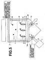
- a surface plasmon enhanced fluorescence sensor such as that illustrated in Figure 5 , is also known as a sensor capable of fluorescence measurement at even higher sensitivity.
- the surface plasmon enhanced fluorescence sensor is disclosed, for example, in Japanese Patent No. 3562912 , and differs from the fluorescence sensor of Figure 4 in that a metal film 20 is formed on the prism 13. That is, surface plasmon is generated within the metal film 20 when the excitation light beam 8 is irradiated thereon, and the electric field amplification effect provided thereby enhances the fluorescence. According to a simulation, the fluorescent intensity has been shown to be enhanced 1000 times.
- Fang Yu et al. propose forming a SAM (Self Assembled Membrane) on the metal film, to separate the fluorescent substance within the sample from the metal film at least by a distance equal to the thickness of the SAM, in Fang Yu et al., "Surface Plasmon Field-Enhanced Fluorescence Spectroscopy Studies of the Interaction between an Antibody and Its Surface-Coupled Antigen", Analytical Chemistry, Vol. 75, pp. 2610-2617, 2003 . Note that Figure 5 illustrates the SAM, denoted by reference number 21. T. Liebermann et al.
- EP-A-0 517 930 discloses a sensor comprising a light source for emitting excitation light, a dielectric block, formed of a material that transmits the excitation light, a metal film formed on a surface of the dielectric block, a sample holding portion for holding a sample and an optical system which causes the excitation light to enter the interface between the dielectric block and the metal film through the dielectric block such that conditions for total internal reflection are satisfied.
- a light beam which is the reflected incident light beam an additional light beam which is "ascribable to fluorescence” is obtained and is detected. This "light which is ascribable to fluorescence" is emitted through inducing surface plasmon rather than fluorescence emitted from fluorescent substances included in the sample, such fluorescence being directly detected as described above with regard to figures 3 to 5 .
- the present invention has been developed in view of the foregoing circumstances. It is an object of the present invention to provide a surface plasmon enhanced fluorescence sensor, which is capable of detecting fluorescence with extremely high sensitivity.
- a surface plasmon enhanced fluorescence sensor of the present invention provides a dielectric film instead of the SAM to achieve the desired objective. More specifically, the surface plasmon enhanced fluorescence sensor of the present invention comprises the features of claim 1.
- a film formed by a polymer may be employed as the non flexible dielectric film.
- the non flexible polymer film it is desirable for hydrophilic linkers, for bonding with a specific substance, to be formed on the non flexible polymer film.
- a second messenger is a substance that cause intracellular signals to be transmitted, by sensing a bond between a receptor and a ligand (agonist), when stimulus from outside a cell is communicated to the interior of the cell via an intracellular communications system by the bond between the receptor and the ligand.
- second messengers include cAMP and inositol phosphate.
- the second messengers are cAMP.
- the surface plasmon enhanced fluorescence sensor of the present invention prefferably comprises: a kit that causes a labeled substance, which is an integrated substance constituted by the substance that directly bonds with the capture molecules and a fluorescent substance excited by the evanescent waves, to be included within the sample.
- a labeled substance which is an integrated substance constituted by the substance that directly bonds with the capture molecules and a fluorescent substance excited by the evanescent waves, to be included within the sample.
- the fluorescence detecting method of the present invention is a method that employs the aforementioned surface plasmon enhanced fluorescence sensor, having the capture molecules that bond with a specific substance immobilized on the dielectric film, comprising the steps of:
- the reason why the sensitivity of fluorescence detection in the conventional surface plasmon enhanced fluorescence sensor provided with the SAM is not improved much is because the SAM is "spongy". Therefore, the thickness of the SAM varies easily, which causes fluorescent substances within sample liquids to approach the metal film to distances where metallic light loss occurs.
- the surface plasmon enhanced fluorescence sensor of the present invention provides the non flexible film having a thickness of 20 to 100nm on the metal film, based on the above discoveries. Therefore, fluorescent substances within sample liquids can be prevented from approaching the metal film to distances where metallic light loss occurs. According to this sensor, the aforementioned metallic light loss cannot occur, the electric field amplification effect of surface plasmon can be positively obtained, and fluorescence can be detected at extremely high sensitivity.
- the non flexible film is formed by hydrophobic material, based on the above discoveries. Therefore, molecules that cause light loss, such as metal ions and dissolved oxygen, which are present within sample liquids, are prevented from entering the interior of the non flexible film. Accordingly, the excitation energy of excitation light beams can be prevented from being robbed by these molecules. Therefore, the surface plasmon enhanced sensor of the present invention can secure extremely high excitation energy, and fluorescence can be detected at extremely high sensitivity.
- non flexible means that the film has rigidity to a degree that it will not deform such that the thickness thereof changes during normal use of the sensor.
- the lower and upper limits of the film thickness are set to 20nm and 100nm for the following reasons.
- Light loss occurs in molecules of fluorescent substances which are present in the vicinity of metal, due to energy transition to the metal.
- the degree of energy transition is inversely proportionate to the distance between the molecules and the metal to the third power in the case that the metal is a plane which is infinitely thick.
- the degree of energy transition is inversely proportionate to the distance between the molecules and the metal to the fourth power in the case that the metal is a plane which is infinitely thin.
- the degree of energy transition is inversely proportionate to the distance between the molecules and the metal to the sixth power in the case that the metal is in the form of fine particles.
- the lower limit of the film thickness is set to 20nm in the present invention.
- the fluorescent substance molecules are excited by the evanescent waves which leak from the surface of the metal film and which are amplified by surface plasmon.
- the range of travel (distance from the surface of the metal film) of evanescent waves is at most approximately one wavelength, and it is known that the electric field intensity thereof attenuates drastically at an exponential rate corresponding to the distance from the surface of the metal film.
- Figure 6 illustrates calculation results of the relationship between the electric field intensity and the distance from the metal film, for visible light having a wavelength of 635nm. As can be seen from the graph of Figure 6 , leakage of the evanescent wave occurs only for a distance approximately corresponding to the wavelength (635nm), and the electric field intensity drops drastically beyond 100nm.
- the electric field that excites the fluorescent substance molecules It is desirable for the electric field that excites the fluorescent substance molecules to be as great as possible. Therefore, it is desirable to set the distance between the surface of the metal film and the fluorescent substance molecules to be 100nm or less, to perform effective excitation. Accordingly, the upper limit of the film thickness is set to 100nm in the present invention.
- an example of a preferable material that possesses the aforementioned desired properties is a polymer.
- proteins and the like which are present within sample liquids are easily non specifically adsorbed onto polymers.
- antigens which are specifically adsorbed onto antibodies which are coated on the surface of the non flexible film are to be detected by fluorometry, for example, the non specific adsorption of the proteins yields the same result as the specific adsorption of the antigens, which may cause false positive detection to occur.
- the linkers block the proteins and the like. Therefore, the proteins and the like are prevented from being non specifically adsorbed on to the non flexible film, and false positive detection is prevented.
- antibodies and the like which are to be provided on the surface of the non flexible film may be specifically bonded with the linkers, to be supplied on the surface of the non flexible film.
- materials of the non flexible film are hydrophobic high polymers and films that contain inorganic oxides.
- Hydrophobic polymers to be utilized in the present invention preferably include monomers, which have solubilities of 20% by weight with respect to water, at 50% by weight or greater.
- the solubility of a monomer that forms a hydrophobic polymer with respect to water at a temperature of 25° can be measured by the method described in " New Basic Techniques for Experimental Chemistry” (Maruzen Chemical, 1975 ).
- the solubilities of monomers to be utilized in the present invention with respect to water at a temperature of 20°C measured by this method are: 0.00% by weight for 2 ethyl hexyl methacrylate; 0.03% by weight for styrene; 1.35% by weight for methyl methacrylate; 0.32% by weight for butyl acrylate; and 0.03% by weight for butyl methacrylate.
- As an index for solubility of the hydrophobic high polymer film to be used in the present invention with respect to water is preferably 10% by weight or less, and further 1% by weight or less.
- the monomers having solubilities of 20% by weight or less with respect to water to be used in the present invention include: vinyl esters; acrylates; methacrylates; olefins; styrenes; crotonates; itaconic acid esters; maleate esters; fumarate esters; allyl compounds; vinyl ethers; and vinyl ketones.
- Styrene, methacrylate methyl, methacrylate hexafluoropropane, vinyl acetate, and acrylonitryl may be used.
- a homopolymer constituted by a single type of monomer, or a copolymer constituted by two or more types of monomers may be used as the hydrophobic high polymer compound.
- a high polymer compound which is a copolymer of a monomer that has a solubility of 20% by weight or less with respect to water and a monomer that has a solubility of 20% by weight or greater, may be employed.
- monomers that have solubilities of 20% by weight or greater with respect to water include: methacrylate 2-hydroxy ethyl; methacrylate; acrylate; and allyl alcohol.
- Polyacrylates, polymethacrylates, polyester, and polystyrene are preferable as the hydrophobic high polymers to be employed in the present invention.
- these hydrophobic high polymers film formation is facilitated, and at the same time, exposure of functional bases for immobilizing biologically active substances thereon is also facilitated.
- oxidation treatment such as a UV/ozone treatment
- Silica, alumina, titania, zirconia, ferrite, composites, and derivatives thereof may be utilized as the inorganic oxides in the present invention.
- Conventional methods may be used to form the film. Examples of methods which may be used to form the film include: the sol gel method; the sputtering method; the vapor deposition method; and the plating method.
- the capture molecules that bond with a specific substance, such as second messengers within living tissue are provided on the non flexible film of the surface plasmon enhanced fluorescence sensor of the present invention, so called “competitive" fluorescence detection can be favorably adopted.
- the competitive fluorescence detection is adopted, because fluorescence detection with high sensitivity is enabled by the surface plasmon enhancement, B/F separation (Bound/Free separation), which had heretofore been considered difficult with "sandwich” fluorescence detection using two types of capture molecules, can be obviated, while high sensitivity can be realized at the same time. If B/F separation can be obviated, deterioration in sensitivity that occurs due to cleansing fluctuations in the competitive detecting method can be prevented.
- the capture molecules are not limited to any particular molecule, as long as they are molecules that bond with a specific substance.
- the capture molecules include: antibodies; fragments of antibodies; adaptors constituted by nucleic acid; inclusion compounds; and template molecules constructed by molecular imprinting.
- Dissociation equilibrium constants (Kd) are indices that represent the bonding properties of capture molecules with respect to specific substances.
- capture molecules having dissociation equilibrium constants Kd of 10 -6 or less, more preferably 10 -7 or less, and even more preferably 10 -8 or less are selected. It is desirable for capture molecules that have bonding properties with respect to a specific substance, but do not have bonding properties with respect to other substances, that is, capture molecules having specificity, to be selected and utilized.
- the capture molecules are those that bond with second messengers within living tissue
- the activation of receptors by ligands or inhibition of receptors can be detected or quantized, by measuring the amount of second messengers.
- the surface plasmon enhancement enables detection and/or quantization of the second messengers with high sensitivity.
- the surface plasmon enhanced fluorescence sensor may be equipped with a kit that causes a labeled substance, which is an integrated substance constituted by the substance (such as the second messengers) that directly bonds with the capture molecules and a fluorescent substance excited by the evanescent waves, to be included within the sample.
- the kit can be used to easily introduce a labeled specific substance into the sample. Therefore, the aforementioned competitive fluorescence detection can be performed extremely easily.
- the labeled specific substance may be introduced to the sample in advance.
- the labeled specific substance may be introduced to the sample after a predetermined amount of time elapses after the sample contacts the capture molecules.
- the labeled specific substance may be caused to contact the capture molecules, and after a predetermined amount of time elapses, the sample may be mixed therein.
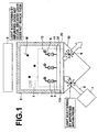
- FIG 1 is a side view that illustrates the schematic structure of a surface plasmon enhanced fluorescence sensor (hereinafter, simply referred to as "fluorescence sensor”) according to a first embodiment of the present invention.
- the fluorescence sensor comprises: a semiconductor laser light source 7, for emitting an excitation light beam 8 having a wavelength of 635nm, for example; a prism 13 (dielectric block), formed of a material that transmits the excitation light beam 8 and provided at a position such that the excitation light beam 8 enters it at an end facet thereof; a metal film 20, formed on a surface 13a of the dielectric block 13; a non flexible polymer film, formed on the metal film 20; a sample holding portion 5, for holding a liquid sample 1 such that the liquid sample 1 contacts the non flexible polymer film 31 at the side opposite the prism 13; and photodetector 9 (fluorescence detecting means), provided above the sample holding portion 5.
- a semiconductor laser light source 7 for emitting an excitation light beam 8 having a wavelength of
- the light source 7 is provided such that the excitation light beam 8 enters the interface between the dielectric block 13 and the metal film 20 through the dielectric block 13 such that conditions for total internal reflection are satisfied. That is, the light source 7 itself functions as an incident optical system that causes the excitation light beam 8 to enter the prism 13 in the manner described above.
- the present invention is not limited to this construction, and an incident optical system constituted by lenses, mirrors, and the like, that causes the excitation light beam 8 to enter the prism 13 in the above manner may be provided separately.
- the prism 13 may be formed by ZEONEX TM 330R (refractive index: 1.50) by Japan Zeon K.K. Meanwhile, the metal film 20 is formed by sputtering gold onto the surface 13a of the prism 13, at t film thickness of 50nm.
- the non flexible film 31 is formed by spin coating a polystyrene polymer having a refractive index of 1.59 onto the metal film 20, at a film thickness of 20nm.
- the prism 13 may be formed by materials other than that described above, such as known resins and optical glass. It can be said that resins are preferable over optical glass, from the viewpoint of cost.
- the prism 13 is to be formed by resin, polymethyl methacrylate (PMMA), polycarbonate (PC), and non crystalline polyolefin (APO) that includes cycloolefin may be favorably employed.
- LAS-1000 by FUJIFILM Corp. may be employed as the photodetector 9.
- the detection targets of the fluorescence sensor are CRP antigens 2 (molecular weight: 110000Da), for example.
- Primary antibodies 4 (monoclonal antibodies) that specifically bond with the CRP antigens 2 are immobilized on the non flexible film 31.
- the primary antibodies 4 are immobilized on the non flexible polymer film 31 via PEG's, of which the ends are carboxylized, by the amine coupling method. Meanwhile, monoclonal antibodies having different epitopes from the primary antibodies 4 are employed as the secondary antibodies 6.
- the secondary antibodies 6 are labeled with a fluorescent substance 10 (Cy5 pigment).
- the amine coupling method comprises the following steps, for example. Note that the following example is for a case that a 30 ⁇ l (micro liter) cuvette/cell is employed.
- the light source 7 is not limited to the semiconductor laser, and other known light sources may be selected and utilized.
- the photodetector 9 is also not limited to that described above, and other known photodetectors, such as CCD' s, PD's (photodiodes), photomultiplier tubes, and c-MOS's may be employed.
- pigment other than Cy5 maybe used as the labeled substance.
- the operation of the fluorescence sensor will be described for a case in which CRP antigens 2 included in the liquid sample 1 are to be detected.
- the method that will be described here is a so called “sandwich” detection method, wherein the CRP antigens 2 are detected when they are sandwiched between two types of antibodies.
- the liquid sample 1 is caused to flow through the sample holding portion 5.
- the secondary antibodies 6, which are labeled with the fluorescent substance 10 and specifically bond with the CRP antigens 2 are caused to flow through the sample holding portion 5.
- the Cy5 pigment emits fluorescence of a predetermined wavelength when excited by excitation light having a wavelength of 635nm.
- the excitation light beam 8 is emitted from the light source 7 toward the prism 13, and fluorescence detection is performed by the photodetector 9.
- evanescent waves 11 leak from the interface between the prism 13 and the metal film 20.
- the secondary antibodies 6 are bonded to the antigens 2, and the fluorescent substance 10, which the secondary antibodies 6 are labeled with, are excited by the evanescent waves 11.
- the excited fluorescent substance 10 emits fluorescence of a predetermined wavelength, and the fluorescence is detected by the photodetector 9.
- the photodetector 9 detects the fluorescence of the predetermined wavelength, it can be confirmed that the secondary antibodies 6 are bonded to the CRP antigens 2, that is, that the CRP antigens 2 are contained in the sample 1.
- the evanescent waves 11 only propagate a distance of several hundreds of nanometers from the interface between the prism 13 and the metal film 20. Therefore, scattering due to impurities in the sample can be substantially eliminated. In addition, light scattered by impurities N within the prism 13 is blocked by the metal film 20, and does not reach the photodetector 9. Accordingly, the fluorescence sensor is capable of virtually eliminating light noise, and fluorescence detection having an extremely high S/N ratio is enabled.
- the fluorescence sensor of the present embodiment is provided with the metal film on the surface 13a of the prism 13, surface plasmon is excited therein.
- the electric field amplification effect provided by the surface plasmon enhances the fluorescence, and the S/N ratio is improved further.
- the non flexible film 31 having a film thickness of 20nm is formed on the metal film 20. Therefore, the fluorescent substance 10 within the sample 1 is prevented from approaching the metal film 20 to a degree that metallic light loss occurs. Accordingly, the aforementioned metallic light loss does not occur in the fluorescence sensor, the electric field amplification effect of the surface plasmon is positively obtained, and fluorescence detection with extremely high sensitivity is enabled.
- the non flexible film 31 is formed by a polystyrene polymer, which is hydrophobic. Therefore, molecules that cause light loss, such as metal ions and dissolved oxygen, which are present within the sample 1, are prevented from entering the interior of the non flexible film 31. Accordingly, the excitation energy of the excitation light beam 8 can be prevented from being robbed by these molecules. Therefore, the surface plasmon enhanced sensor can secure extremely high excitation energy, and fluorescence can be detected at extremely high sensitivity.
- the fluorescence sensor of the second embodiment basically differs from that of the first embodiment in that hydrophilic linkers 32 are bonded to the surface of the non flexible film 31.
- the secondary antibodies 6 and the antigens 2 are non specifically adsorbed to the surface of the non flexible film 31 formed by a polystyrene polymer.
- the non specific adsorption of the antibodies 6 and the antigens 2 yields the same result as the specific adsorption of the antigens 2, which may cause false positive detection of the antigens 2 to occur.
- the linkers 32 that bond with the primary antibodies 4 are formed on the non flexible film 32.
- the linkers 32 block the secondary antibodies 6 and the antigens 2. Therefore, the secondary antibodies 6 and the antigens 2 are prevented from being non specifically adsorbed onto the non flexible film 31, and false positive detection is prevented.
- the primary antibodies 4 which are to be provided on the surface of the non flexible film 31 may be specifically bonded with the linkers 32, to be supplied on the surface of the non flexible film 31.
- Table 1 below compare and illustrate the detection limits of the fluorescence sensor of the second embodiment and conventional fluorescence sensors.
- the columns indicated by A, B, C, and D represent the detection limit of a conventional sensor having a basic structure as illustrated in Figure 3 , a conventional sensor that employs the ELISA method, a conventional sensor having a basic structure as illustrated in Figure 4 , and the fluorescence sensor of the second embodiment, respectively.
- the ELISA method is a known method that amplifies fluorescence detection signals, by increasing the amount of a fluorescent substance (pigment) utilizing oxygen reactions.
- the CRP antigens 2 were detected at concentrations of 50pM (pico mol), 5pM, 500fM (femto mol), 50fM, 5fM, 500aM (atto mol), and 50aM.
- the detection limits are represented by the smallest mol concentration that each sensor was capable of detecting.
- the surface plasmon enhanced fluorescence sensor of the present invention is capable of fluorescence detection at sensitivities 2 to 4 powers of 10 greater than conventional sensors.
- the non flexible film 31 and the prism 13 to have similar coefficients of thermal expansion. That is, if the coefficients of thermal expansion of the two components are different to a great degree, separation or decrease in the degree of close contact becomes likely when temperature changes occur. Specifically, it is desirable for the difference between the coefficients of linear (thermal) expansion of the two components to be within a range of 35x10 -6 .
- the metal film 20 is provided between the non flexible film 31 and the prism 13. However, if temperature changes occur, the metal film 20 expands and contracts along with the non flexible film 31 above and the prism 13 below.
- the coefficients of thermal expansion of the non flexible film 31 and the prism 13 it is preferable for the coefficients of thermal expansion of the non flexible film 31 and the prism 13 to be similar.
- the non flexible film 31 is formed by a polymer, it is preferable to select resin as the material of the prism 13 over glass.
- Table 2 illustrates the main substances which are employed as materials of the prism 13 and the non flexible film 31 and their coefficients of linear (thermal) expansion, along with the coefficients of linear (thermal) expansion of water and gold, as references. It is desirable for materials having coefficients of linear (thermal) expansion with differences therebetween being within the range of 35x10 -6 to be selected as the materials of the prism 13 and the non flexible film 31.
- the fluorescence sensor of the third embodiment basically differs from that of the first embodiment in that a labeled specific substance, which is an integrated substance constituted by a substance that directly bonds with capture molecules, such as antibodies, and a fluorescent substance excited by the evanescent waves, are included within the sample.
- a labeled specific substance which is an integrated substance constituted by a substance that directly bonds with capture molecules, such as antibodies, and a fluorescent substance excited by the evanescent waves, are included within the sample.
- second messengers 41 which are present within living tissue, are the detection targets, and capture molecules 40 that directly bond with the second messengers 41 are employed.
- the labeled specific substance which is an integrated substance constituted by the fluorescent substance 10 and the second messengers 41, is also contained in the sample 1.
- the labeled specific substance may be contained in the sample 1 in advance.
- the labeled specific substance may be introduced to the sample 1 after a predetermined amount of time elapses after the sample 1 contacts the capture molecules 40.
- the labeled specific substance may be caused to contact the capture molecules 40, and after a predetermined amount of time elapses, the sample 1 may be mixed therein.
- the labeled specific substance may be sold with the fluorescence sensor, or as a kit to be employed with the fluorescence sensor. In these cases, the labeled specific substance is readily available to users of the sensors, which is favorable because competitive fluorescence detection can be easily executed.
- the second messengers 41 can be detected with high sensitivity, and detection and/or quantization of low molecular compounds, which is difficult with the sandwich detection method, can be easily executed.
Landscapes
- Health & Medical Sciences (AREA)
- Chemical & Material Sciences (AREA)
- Immunology (AREA)
- Physics & Mathematics (AREA)
- Life Sciences & Earth Sciences (AREA)
- Analytical Chemistry (AREA)
- Biochemistry (AREA)
- General Health & Medical Sciences (AREA)
- General Physics & Mathematics (AREA)
- Nuclear Medicine, Radiotherapy & Molecular Imaging (AREA)
- Pathology (AREA)
- Chemical Kinetics & Catalysis (AREA)
- Optics & Photonics (AREA)
- Investigating, Analyzing Materials By Fluorescence Or Luminescence (AREA)
- Investigating Or Analysing Materials By The Use Of Chemical Reactions (AREA)
Claims (7)
- Oberflächenplasmonen-verstärkter Fluoreszenzsensor, umfassend:eine Lichtquelle (7) zum Emittieren eines Anregungslichtstrahlbündels (8) einer vorbestimmten Wellenlänge;einen dielektrischen Block (13), der aus einem Werkstoff gefertigt ist, der das Anregungslichtstrahlbündel (8) durchlässt;einen Metallfilm (20), der auf einer Fläche (13a) des dielektrischen Blocks (13) gebildet ist;einem Probenhalteteil (5) zum Halten einer Probe (1);eine Eintrittsoptik zum Veranlassen des Anregungslichtstrahlbündels (8), in die Grenzfläche zwischen dem dielektrischen Block (13) und dem Metallfilm (20) durch den elektrischen Block (13) hindurch derart einzutreten, dass Bedingungen für innere Totalreflexion erfüllt sind;eine Fluoreszenz-Detektoreinrichtung (19) zum Detektieren von Fluoreszenz, die von einer Substanz innerhalb der Probe emittiert wird, welche angeregt wird durch evaneszente Wellen (11), die von der Grenzfläche her streuen, während das Anregungslichtstrahlbündel (8) in die Grenzfläche eintritt, wobei die Fluoreszenz-Detektoreinrichtung auf der dem dielektrischen Block (13) abgewandten Seite der Probe vorgesehen ist, gekennzeichnet durch:wobei der Film Steifigkeit in einem Maß besitzt, dass er sich im normalen Gebrauch nicht mit einhergehender Änderung seiner Dicke verformt, und der Film auf dem Metallfilm (20) mit einer Filmdicke in dem Bereich von 20-100 nm gebildet ist;einen dielektrischen, nicht-flexiblen Film (31) aus einem hydrophoben Werkstoff,
wobei der Probenhalteteil (5) eine Probe (1) derart hält, dass die Probe (1) den dielektrischen, nicht-flexiblen Film (31) berührt. - Oberflächenplasmonen-verstärkter Fluoreszenzsensor nach Anspruch 1, bei dem der dielektrische Film (31) aus einem Polymer gebildet ist.
- Oberflächenplasmonen-verstärkter Fluoreszenzsensor nach Anspruch 2, weiterhin umfassend:hydrophile Linker (32) zum Binden einer spezifischen Substanz (4), ausgebildet auf dem nicht-flexiblen Polymerfilm (31).
- Oberflächenplasmonen-verstärkter Fluoreszenzsensor nach Anspruch 1, bei dem an dem dielektrischen Film (31) Fangmoleküle (40) zum Binden einer spezifischen Substanz (41) immobilisiert sind.
- Oberflächenplasmonen-verstärkter Fluoreszenzsensor nach Anspruch 4, bei dem
die Fangmoleküle (40) jene sind, die eine Bindung mit breiten Messangern (41) innerhalb von Lebendgewebe eingehen. - Oberflächenplasmonen-verstärkter Fluoreszenzsensor nach Anspruch4, weiterhin umfassend:Ein Kit, das eine markierte Substanz, bei der es sich um eine integrierte Substanz handelt, gebildet von der Substanz (41), die eine direkte Bindung mit den Fangmolekülen (40) eingeht, und einer Fluoreszenz-Substanz (10), die durch die evaneszenten Wellen (11) angeregt wird, dazu bringt, innerhalb der Probe (1) eingeschlossen zu sein.
- Fluoreszenz-Nachweisverfahren, welches von dem Oberflächenplasmonenverstärkten Fluoreszenzsensor nach einem der Ansprüche 4-6 Gebrauch macht, umfassend die Schritte:Veranlassen einer markierten Substanz, bei der es sich um eine integrierte Substanz handelt, die gebildet wird durch eine Substanz (41), die eine direkte Bildung mit den Fangmolekülen (40) eingeht, und einer durch die evaneszenten Wellen (11) angeregten Fluoreszenz-Substanz (11), innerhalb der Probe (11) enthalten zu sein;Nachweisen der Fluoreszenz.
Applications Claiming Priority (2)
| Application Number | Priority Date | Filing Date | Title |
|---|---|---|---|
| JP2006255374 | 2006-09-21 | ||
| JP2007057098A JP2008102117A (ja) | 2006-09-21 | 2007-03-07 | 表面プラズモン増強蛍光センサおよび蛍光検出方法 |
Publications (3)
| Publication Number | Publication Date |
|---|---|
| EP1903330A2 EP1903330A2 (de) | 2008-03-26 |
| EP1903330A3 EP1903330A3 (de) | 2008-10-29 |
| EP1903330B1 true EP1903330B1 (de) | 2010-06-02 |
Family
ID=38691789
Family Applications (1)
| Application Number | Title | Priority Date | Filing Date |
|---|---|---|---|
| EP20070018482 Not-in-force EP1903330B1 (de) | 2006-09-21 | 2007-09-20 | Oberflächenplasmonverstärkter Fluoreszenzsensor und Verfahren zur Fluoreszenzdetektion |
Country Status (5)
| Country | Link |
|---|---|
| US (1) | US7738107B2 (de) |
| EP (1) | EP1903330B1 (de) |
| JP (1) | JP2008102117A (de) |
| AT (1) | ATE470144T1 (de) |
| DE (1) | DE602007006876D1 (de) |
Families Citing this family (19)
| Publication number | Priority date | Publication date | Assignee | Title |
|---|---|---|---|---|
| JP2009098009A (ja) | 2007-10-17 | 2009-05-07 | Fujifilm Corp | 蛍光検出装置およびその装置に使用される微小開孔金属薄膜の作製方法 |
| JP2009128136A (ja) * | 2007-11-22 | 2009-06-11 | Fujifilm Corp | 蛍光検出方法 |
| JP2009276162A (ja) * | 2008-05-14 | 2009-11-26 | Fujifilm Corp | 蛍光検出方法 |
| JP5095552B2 (ja) * | 2008-08-11 | 2012-12-12 | 富士フイルム株式会社 | 検出方法および検出システム |
| JP2010117245A (ja) * | 2008-11-13 | 2010-05-27 | Fujifilm Corp | 質量分析方法 |
| KR101183159B1 (ko) | 2008-12-22 | 2012-09-17 | 한국전자통신연구원 | 바이오 칩 및 이를 이용한 바이오 물질 검출 장치 |
| JP5033820B2 (ja) * | 2009-02-03 | 2012-09-26 | 株式会社日立ハイテクノロジーズ | 全反射顕微鏡装置、及び蛍光試料分析方法 |
| WO2011043202A1 (ja) | 2009-10-05 | 2011-04-14 | コニカミノルタホールディングス株式会社 | 表面プラズモン増強蛍光測定装置 |
| WO2013161614A1 (ja) | 2012-04-27 | 2013-10-31 | コニカミノルタ株式会社 | 酵素処理工程を含むレクチンを用いた抗原検出方法 |
| CN103175827B (zh) * | 2013-03-15 | 2015-03-04 | 武汉大学 | 一种检测5-羟甲基脱氧尿苷的化学方法 |
| HRP20251426T1 (hr) | 2013-05-06 | 2026-01-02 | Scholar Rock, Inc. | Sastavi i postupci za modulaciju faktora rasta |
| JP5655125B2 (ja) * | 2013-10-09 | 2015-01-14 | 富士フイルム株式会社 | 蛍光検出方法 |
| EP3088896B1 (de) | 2013-12-27 | 2019-11-06 | Konica Minolta, Inc. | Verfahren zur auswertung von informationen zur diagnose und kit dafür |
| US10222385B2 (en) | 2013-12-27 | 2019-03-05 | Konica Minolta, Inc. | Methods for discriminating between prostate cancer and a benign prostate-disease |
| WO2016047427A1 (ja) * | 2014-09-24 | 2016-03-31 | コニカミノルタ株式会社 | プリズム、プリズムの製造方法、金型およびセンサーチップ |
| WO2017057136A1 (ja) * | 2015-09-29 | 2017-04-06 | コニカミノルタ株式会社 | 表面プラズモン励起増強蛍光分光測定方法、および測定用キット |
| US10648914B2 (en) * | 2015-11-11 | 2020-05-12 | Konica Minolta, Inc. | Optical sample detection system |
| CN106483113A (zh) * | 2016-10-26 | 2017-03-08 | 华南师范大学 | 1‑芘甲酸作为pH荧光探针的应用 |
| JPWO2020179611A1 (de) * | 2019-03-01 | 2020-09-10 |
Family Cites Families (27)
| Publication number | Priority date | Publication date | Assignee | Title |
|---|---|---|---|---|
| EP0341927B1 (de) * | 1988-05-10 | 1993-07-14 | AMERSHAM INTERNATIONAL plc | Biosensoren |
| GB8817710D0 (en) * | 1988-07-25 | 1988-09-01 | Ares Serono Res & Dev Ltd | Method of assay |
| US5340715A (en) * | 1991-06-07 | 1994-08-23 | Ciba Corning Diagnostics Corp. | Multiple surface evanescent wave sensor with a reference |
| EP0517930B1 (de) * | 1991-06-08 | 1995-05-24 | Hewlett-Packard GmbH | Verfahren und Gerät zur Feststellung und/oder Konzentrationsbestimmung von Biomolekülen |
| US5629213A (en) * | 1995-03-03 | 1997-05-13 | Kornguth; Steven E. | Analytical biosensor |
| JP3562912B2 (ja) * | 1996-09-04 | 2004-09-08 | 富士写真フイルム株式会社 | 表面プラズモンセンサー |
| US6180288B1 (en) * | 1997-03-21 | 2001-01-30 | Kimberly-Clark Worldwide, Inc. | Gel sensors and method of use thereof |
| US6330062B1 (en) * | 1999-04-30 | 2001-12-11 | Wisconsin Alumni Research Foundation | Fourier transform surface plasmon resonance adsorption sensor instrument |
| US6784999B1 (en) * | 1999-05-17 | 2004-08-31 | The Florida International University Board Of Trustees | Surface plasmon resonance detection with high angular resolution and fast response time |
| KR100883079B1 (ko) * | 1999-07-05 | 2009-02-10 | 노파르티스 아게 | 플랫폼, 플랫폼을 가지는 장치, 및 플랫폼을 사용하는 방법 |
| JP3249954B2 (ja) * | 1999-07-07 | 2002-01-28 | 科学技術振興事業団 | 蛍光免疫分析方法及び装置 |
| US20040023293A1 (en) * | 1999-09-27 | 2004-02-05 | Kreimer David I. | Biochips for characterizing biological processes |
| US7273868B2 (en) * | 2000-04-28 | 2007-09-25 | Tanabe Seiyaku Co., Ltd. | Pyrazine derivatives |
| US7193711B2 (en) * | 2000-07-11 | 2007-03-20 | Maven Technologies, Llc | Imaging method and apparatus |
| JP4908721B2 (ja) | 2000-07-17 | 2012-04-04 | 中外製薬株式会社 | 生理活性を有するリガンドのスクリーニング方法 |
| US6992770B2 (en) * | 2001-01-25 | 2006-01-31 | Fuji Photo Film Co., Ltd. | Sensor utilizing attenuated total reflection |
| KR100407821B1 (ko) * | 2001-11-23 | 2003-12-01 | 한국전자통신연구원 | 활성이온의 상향전이를 이용한 도파로-플라즈몬 공명 센서및 이미징 시스템 |
| JP3741277B2 (ja) * | 2002-03-29 | 2006-02-01 | 富士写真フイルム株式会社 | 測定チップ及びその製造方法 |
| JP2004061211A (ja) * | 2002-07-26 | 2004-02-26 | Shimadzu Corp | 蛍光検出方法及び装置 |
| US6956651B2 (en) * | 2002-09-07 | 2005-10-18 | Hilary S. Lackritz | Bioanalysis systems including optical integrated circuit |
| US7027163B2 (en) * | 2003-01-24 | 2006-04-11 | General Dynamics Advanced Information Systems, Inc. | Grating sensor |
| KR100500610B1 (ko) * | 2003-10-29 | 2005-07-11 | 한국전기연구원 | 형광 현미경 및 이를 사용한 관측 방법 |
| JP4125247B2 (ja) * | 2004-01-08 | 2008-07-30 | 富士フイルム株式会社 | 固体基板の製造方法 |
| US7501289B2 (en) * | 2003-12-25 | 2009-03-10 | Fujifilm Corporation | Biosensor |
| EP1812594B1 (de) * | 2004-11-18 | 2013-01-09 | Eppendorf Array Technologies | Echtzeitquantifizierung mehrerer ziele auf einem mikro-array |
| JP4370383B2 (ja) * | 2005-01-26 | 2009-11-25 | 独立行政法人産業技術総合研究所 | プラズモン共鳴蛍光を用いた生体分子相互作用検出装置及び検出方法 |
| JP2006208294A (ja) * | 2005-01-31 | 2006-08-10 | Canon Inc | プラズモン共鳴および蛍光の同時イメージング装置及びイメージング方法 |
-
2007
- 2007-03-07 JP JP2007057098A patent/JP2008102117A/ja active Pending
- 2007-09-20 EP EP20070018482 patent/EP1903330B1/de not_active Not-in-force
- 2007-09-20 AT AT07018482T patent/ATE470144T1/de not_active IP Right Cessation
- 2007-09-20 DE DE200760006876 patent/DE602007006876D1/de active Active
- 2007-09-21 US US11/859,027 patent/US7738107B2/en not_active Expired - Fee Related
Also Published As
| Publication number | Publication date |
|---|---|
| US20080074671A1 (en) | 2008-03-27 |
| DE602007006876D1 (de) | 2010-07-15 |
| ATE470144T1 (de) | 2010-06-15 |
| EP1903330A3 (de) | 2008-10-29 |
| EP1903330A2 (de) | 2008-03-26 |
| JP2008102117A (ja) | 2008-05-01 |
| US7738107B2 (en) | 2010-06-15 |
Similar Documents
| Publication | Publication Date | Title |
|---|---|---|
| EP1903330B1 (de) | Oberflächenplasmonverstärkter Fluoreszenzsensor und Verfahren zur Fluoreszenzdetektion | |
| CN102165305B (zh) | 检测系统与方法 | |
| JP5180703B2 (ja) | 検出方法、検出用試料セルおよび検出用キット | |
| US10976255B2 (en) | Optical detection method and optical detection device | |
| JP5152917B2 (ja) | 検出方法、検出用試料セルおよび検出用キット | |
| US8106368B2 (en) | Fluorescence detecting method | |
| US20090116020A1 (en) | Biosensor, method for producing the same and sensor measurement system | |
| US7612349B2 (en) | Surface plasmon enhanced fluorescence sensor | |
| TW201305548A (zh) | 用於細胞分析之系統及方法 | |
| WO2009078511A1 (en) | Fluorescence microscope using surface plasmon resonance | |
| WO2010134592A1 (ja) | Spfs-lpfs系による測定方法に供するプラズモン励起センサおよびアッセイ法 | |
| JP2969177B2 (ja) | 分析方法 | |
| JP5958339B2 (ja) | 近接場増強蛍光センサチップ | |
| JP2010145272A (ja) | プラズモン励起センサを用いたアッセイ法 | |
| US20120322166A1 (en) | Fluorescence detecting apparatus, sample cell for detecting fluorescence, and fluorescence detecting method | |
| JP5516198B2 (ja) | プラズモン励起センサチップおよびこれを用いたプラズモン励起センサ、並びにアナライトの検出方法 | |
| JP2009250960A (ja) | 生体分子の検出方法、生体分子捕捉物質及び生体分子検出装置 | |
| JP2008203172A (ja) | 表面プラズモン増強蛍光検出方法 | |
| JP2009128136A (ja) | 蛍光検出方法 | |
| US7701579B2 (en) | Fluorescence sensor | |
| He et al. | Study of cell adhesion and migration by using a plasmon-enhanced total internal reflection fluorescence microscope | |
| JP2011169609A (ja) | プラズモン励起センサを用いたアッセイ法 | |
| WO2023247426A1 (en) | Plasmon-enhanced digital immunofluorescence assays | |
| JP6414209B2 (ja) | 表面プラズモン増強蛍光測定方法および表面プラズモン増強蛍光測定装置 | |
| JP5516197B2 (ja) | プラズモン励起センサおよび該センサを用いたアッセイ法 |
Legal Events
| Date | Code | Title | Description |
|---|---|---|---|
| PUAI | Public reference made under article 153(3) epc to a published international application that has entered the european phase |
Free format text: ORIGINAL CODE: 0009012 |
|
| AK | Designated contracting states |
Kind code of ref document: A2 Designated state(s): AT BE BG CH CY CZ DE DK EE ES FI FR GB GR HU IE IS IT LI LT LU LV MC MT NL PL PT RO SE SI SK TR |
|
| AX | Request for extension of the european patent |
Extension state: AL BA HR MK YU |
|
| PUAL | Search report despatched |
Free format text: ORIGINAL CODE: 0009013 |
|
| AK | Designated contracting states |
Kind code of ref document: A3 Designated state(s): AT BE BG CH CY CZ DE DK EE ES FI FR GB GR HU IE IS IT LI LT LU LV MC MT NL PL PT RO SE SI SK TR |
|
| AX | Request for extension of the european patent |
Extension state: AL BA HR MK RS |
|
| 17P | Request for examination filed |
Effective date: 20090428 |
|
| AKX | Designation fees paid |
Designated state(s): AT BE BG CH CY CZ DE DK EE ES FI FR GB GR HU IE IS IT LI LT LU LV MC MT NL PL PT RO SE SI SK TR |
|
| 17Q | First examination report despatched |
Effective date: 20090810 |
|
| GRAP | Despatch of communication of intention to grant a patent |
Free format text: ORIGINAL CODE: EPIDOSNIGR1 |
|
| GRAS | Grant fee paid |
Free format text: ORIGINAL CODE: EPIDOSNIGR3 |
|
| GRAA | (expected) grant |
Free format text: ORIGINAL CODE: 0009210 |
|
| AK | Designated contracting states |
Kind code of ref document: B1 Designated state(s): AT BE BG CH CY CZ DE DK EE ES FI FR GB GR HU IE IS IT LI LT LU LV MC MT NL PL PT RO SE SI SK TR |
|
| REG | Reference to a national code |
Ref country code: GB Ref legal event code: FG4D |
|
| REG | Reference to a national code |
Ref country code: CH Ref legal event code: EP |
|
| REG | Reference to a national code |
Ref country code: CH Ref legal event code: NV Representative=s name: BOVARD AG PATENTANWAELTE |
|
| REG | Reference to a national code |
Ref country code: IE Ref legal event code: FG4D |
|
| REF | Corresponds to: |
Ref document number: 602007006876 Country of ref document: DE Date of ref document: 20100715 Kind code of ref document: P |
|
| REG | Reference to a national code |
Ref country code: SE Ref legal event code: TRGR |
|
| REG | Reference to a national code |
Ref country code: NL Ref legal event code: VDEP Effective date: 20100602 |
|
| PG25 | Lapsed in a contracting state [announced via postgrant information from national office to epo] |
Ref country code: LT Free format text: LAPSE BECAUSE OF FAILURE TO SUBMIT A TRANSLATION OF THE DESCRIPTION OR TO PAY THE FEE WITHIN THE PRESCRIBED TIME-LIMIT Effective date: 20100602 |
|
| LTIE | Lt: invalidation of european patent or patent extension |
Effective date: 20100602 |
|
| PG25 | Lapsed in a contracting state [announced via postgrant information from national office to epo] |
Ref country code: LV Free format text: LAPSE BECAUSE OF FAILURE TO SUBMIT A TRANSLATION OF THE DESCRIPTION OR TO PAY THE FEE WITHIN THE PRESCRIBED TIME-LIMIT Effective date: 20100602 Ref country code: SI Free format text: LAPSE BECAUSE OF FAILURE TO SUBMIT A TRANSLATION OF THE DESCRIPTION OR TO PAY THE FEE WITHIN THE PRESCRIBED TIME-LIMIT Effective date: 20100602 Ref country code: FI Free format text: LAPSE BECAUSE OF FAILURE TO SUBMIT A TRANSLATION OF THE DESCRIPTION OR TO PAY THE FEE WITHIN THE PRESCRIBED TIME-LIMIT Effective date: 20100602 Ref country code: AT Free format text: LAPSE BECAUSE OF FAILURE TO SUBMIT A TRANSLATION OF THE DESCRIPTION OR TO PAY THE FEE WITHIN THE PRESCRIBED TIME-LIMIT Effective date: 20100602 |
|
| PG25 | Lapsed in a contracting state [announced via postgrant information from national office to epo] |
Ref country code: PL Free format text: LAPSE BECAUSE OF FAILURE TO SUBMIT A TRANSLATION OF THE DESCRIPTION OR TO PAY THE FEE WITHIN THE PRESCRIBED TIME-LIMIT Effective date: 20100602 Ref country code: CY Free format text: LAPSE BECAUSE OF FAILURE TO SUBMIT A TRANSLATION OF THE DESCRIPTION OR TO PAY THE FEE WITHIN THE PRESCRIBED TIME-LIMIT Effective date: 20100602 |
|
| PG25 | Lapsed in a contracting state [announced via postgrant information from national office to epo] |
Ref country code: EE Free format text: LAPSE BECAUSE OF FAILURE TO SUBMIT A TRANSLATION OF THE DESCRIPTION OR TO PAY THE FEE WITHIN THE PRESCRIBED TIME-LIMIT Effective date: 20100602 Ref country code: GR Free format text: LAPSE BECAUSE OF FAILURE TO SUBMIT A TRANSLATION OF THE DESCRIPTION OR TO PAY THE FEE WITHIN THE PRESCRIBED TIME-LIMIT Effective date: 20100903 Ref country code: NL Free format text: LAPSE BECAUSE OF FAILURE TO SUBMIT A TRANSLATION OF THE DESCRIPTION OR TO PAY THE FEE WITHIN THE PRESCRIBED TIME-LIMIT Effective date: 20100602 |
|
| PG25 | Lapsed in a contracting state [announced via postgrant information from national office to epo] |
Ref country code: RO Free format text: LAPSE BECAUSE OF FAILURE TO SUBMIT A TRANSLATION OF THE DESCRIPTION OR TO PAY THE FEE WITHIN THE PRESCRIBED TIME-LIMIT Effective date: 20100602 Ref country code: BE Free format text: LAPSE BECAUSE OF FAILURE TO SUBMIT A TRANSLATION OF THE DESCRIPTION OR TO PAY THE FEE WITHIN THE PRESCRIBED TIME-LIMIT Effective date: 20100602 Ref country code: CZ Free format text: LAPSE BECAUSE OF FAILURE TO SUBMIT A TRANSLATION OF THE DESCRIPTION OR TO PAY THE FEE WITHIN THE PRESCRIBED TIME-LIMIT Effective date: 20100602 Ref country code: IS Free format text: LAPSE BECAUSE OF FAILURE TO SUBMIT A TRANSLATION OF THE DESCRIPTION OR TO PAY THE FEE WITHIN THE PRESCRIBED TIME-LIMIT Effective date: 20101002 Ref country code: PT Free format text: LAPSE BECAUSE OF FAILURE TO SUBMIT A TRANSLATION OF THE DESCRIPTION OR TO PAY THE FEE WITHIN THE PRESCRIBED TIME-LIMIT Effective date: 20101004 Ref country code: SK Free format text: LAPSE BECAUSE OF FAILURE TO SUBMIT A TRANSLATION OF THE DESCRIPTION OR TO PAY THE FEE WITHIN THE PRESCRIBED TIME-LIMIT Effective date: 20100602 |
|
| PG25 | Lapsed in a contracting state [announced via postgrant information from national office to epo] |
Ref country code: IT Free format text: LAPSE BECAUSE OF FAILURE TO SUBMIT A TRANSLATION OF THE DESCRIPTION OR TO PAY THE FEE WITHIN THE PRESCRIBED TIME-LIMIT Effective date: 20100602 |
|
| REG | Reference to a national code |
Ref country code: CH Ref legal event code: PFA Owner name: FUJIFILM CORPORATION Free format text: FUJIFILM CORPORATION#26-30, NISHIAZABU 2-CHOME#MINATO-KU TOKYO (JP) -TRANSFER TO- FUJIFILM CORPORATION#26-30, NISHIAZABU 2-CHOME#MINATO-KU TOKYO (JP) |
|
| PLBE | No opposition filed within time limit |
Free format text: ORIGINAL CODE: 0009261 |
|
| STAA | Information on the status of an ep patent application or granted ep patent |
Free format text: STATUS: NO OPPOSITION FILED WITHIN TIME LIMIT |
|
| PG25 | Lapsed in a contracting state [announced via postgrant information from national office to epo] |
Ref country code: DK Free format text: LAPSE BECAUSE OF FAILURE TO SUBMIT A TRANSLATION OF THE DESCRIPTION OR TO PAY THE FEE WITHIN THE PRESCRIBED TIME-LIMIT Effective date: 20100602 Ref country code: MC Free format text: LAPSE BECAUSE OF NON-PAYMENT OF DUE FEES Effective date: 20100930 |
|
| 26N | No opposition filed |
Effective date: 20110303 |
|
| REG | Reference to a national code |
Ref country code: DE Ref legal event code: R097 Ref document number: 602007006876 Country of ref document: DE Effective date: 20110302 |
|
| PG25 | Lapsed in a contracting state [announced via postgrant information from national office to epo] |
Ref country code: IE Free format text: LAPSE BECAUSE OF NON-PAYMENT OF DUE FEES Effective date: 20100920 |
|
| PG25 | Lapsed in a contracting state [announced via postgrant information from national office to epo] |
Ref country code: MT Free format text: LAPSE BECAUSE OF FAILURE TO SUBMIT A TRANSLATION OF THE DESCRIPTION OR TO PAY THE FEE WITHIN THE PRESCRIBED TIME-LIMIT Effective date: 20100602 |
|
| PG25 | Lapsed in a contracting state [announced via postgrant information from national office to epo] |
Ref country code: LU Free format text: LAPSE BECAUSE OF NON-PAYMENT OF DUE FEES Effective date: 20100920 Ref country code: BG Free format text: LAPSE BECAUSE OF FAILURE TO SUBMIT A TRANSLATION OF THE DESCRIPTION OR TO PAY THE FEE WITHIN THE PRESCRIBED TIME-LIMIT Effective date: 20100602 Ref country code: HU Free format text: LAPSE BECAUSE OF FAILURE TO SUBMIT A TRANSLATION OF THE DESCRIPTION OR TO PAY THE FEE WITHIN THE PRESCRIBED TIME-LIMIT Effective date: 20101203 |
|
| PG25 | Lapsed in a contracting state [announced via postgrant information from national office to epo] |
Ref country code: TR Free format text: LAPSE BECAUSE OF FAILURE TO SUBMIT A TRANSLATION OF THE DESCRIPTION OR TO PAY THE FEE WITHIN THE PRESCRIBED TIME-LIMIT Effective date: 20100602 |
|
| PG25 | Lapsed in a contracting state [announced via postgrant information from national office to epo] |
Ref country code: BG Free format text: LAPSE BECAUSE OF FAILURE TO SUBMIT A TRANSLATION OF THE DESCRIPTION OR TO PAY THE FEE WITHIN THE PRESCRIBED TIME-LIMIT Effective date: 20100902 |
|
| PG25 | Lapsed in a contracting state [announced via postgrant information from national office to epo] |
Ref country code: ES Free format text: LAPSE BECAUSE OF FAILURE TO SUBMIT A TRANSLATION OF THE DESCRIPTION OR TO PAY THE FEE WITHIN THE PRESCRIBED TIME-LIMIT Effective date: 20100913 |
|
| PGFP | Annual fee paid to national office [announced via postgrant information from national office to epo] |
Ref country code: CH Payment date: 20140915 Year of fee payment: 8 Ref country code: DE Payment date: 20140917 Year of fee payment: 8 |
|
| PGFP | Annual fee paid to national office [announced via postgrant information from national office to epo] |
Ref country code: SE Payment date: 20140911 Year of fee payment: 8 Ref country code: GB Payment date: 20140917 Year of fee payment: 8 |
|
| PGFP | Annual fee paid to national office [announced via postgrant information from national office to epo] |
Ref country code: FR Payment date: 20140906 Year of fee payment: 8 |
|
| REG | Reference to a national code |
Ref country code: DE Ref legal event code: R119 Ref document number: 602007006876 Country of ref document: DE |
|
| REG | Reference to a national code |
Ref country code: CH Ref legal event code: PL |
|
| REG | Reference to a national code |
Ref country code: SE Ref legal event code: EUG |
|
| GBPC | Gb: european patent ceased through non-payment of renewal fee |
Effective date: 20150920 |
|
| PG25 | Lapsed in a contracting state [announced via postgrant information from national office to epo] |
Ref country code: SE Free format text: LAPSE BECAUSE OF NON-PAYMENT OF DUE FEES Effective date: 20150921 |
|
| REG | Reference to a national code |
Ref country code: FR Ref legal event code: ST Effective date: 20160531 |
|
| PG25 | Lapsed in a contracting state [announced via postgrant information from national office to epo] |
Ref country code: LI Free format text: LAPSE BECAUSE OF NON-PAYMENT OF DUE FEES Effective date: 20150930 Ref country code: DE Free format text: LAPSE BECAUSE OF NON-PAYMENT OF DUE FEES Effective date: 20160401 Ref country code: GB Free format text: LAPSE BECAUSE OF NON-PAYMENT OF DUE FEES Effective date: 20150920 Ref country code: CH Free format text: LAPSE BECAUSE OF NON-PAYMENT OF DUE FEES Effective date: 20150930 |
|
| PG25 | Lapsed in a contracting state [announced via postgrant information from national office to epo] |
Ref country code: FR Free format text: LAPSE BECAUSE OF NON-PAYMENT OF DUE FEES Effective date: 20150930 |