EP1903404A2 - Système de maintenance pour appareil de formation d'images et procédé de maintenance - Google Patents
Système de maintenance pour appareil de formation d'images et procédé de maintenance Download PDFInfo
- Publication number
- EP1903404A2 EP1903404A2 EP07017161A EP07017161A EP1903404A2 EP 1903404 A2 EP1903404 A2 EP 1903404A2 EP 07017161 A EP07017161 A EP 07017161A EP 07017161 A EP07017161 A EP 07017161A EP 1903404 A2 EP1903404 A2 EP 1903404A2
- Authority
- EP
- European Patent Office
- Prior art keywords
- image
- image forming
- data
- forming apparatus
- trouble
- Prior art date
- Legal status (The legal status is an assumption and is not a legal conclusion. Google has not performed a legal analysis and makes no representation as to the accuracy of the status listed.)
- Withdrawn
Links
- 238000012423 maintenance Methods 0.000 title claims abstract description 66
- 238000000034 method Methods 0.000 title claims description 44
- 230000002159 abnormal effect Effects 0.000 claims abstract description 72
- 230000005540 biological transmission Effects 0.000 claims abstract description 27
- 238000004891 communication Methods 0.000 claims description 17
- 238000003860 storage Methods 0.000 claims description 14
- 238000012546 transfer Methods 0.000 description 55
- 230000005856 abnormality Effects 0.000 description 17
- 238000013024 troubleshooting Methods 0.000 description 7
- 239000011521 glass Substances 0.000 description 6
- 238000004140 cleaning Methods 0.000 description 5
- 239000002245 particle Substances 0.000 description 5
- 238000010586 diagram Methods 0.000 description 4
- 230000007774 longterm Effects 0.000 description 4
- 238000003745 diagnosis Methods 0.000 description 3
- 230000006870 function Effects 0.000 description 3
- 238000011835 investigation Methods 0.000 description 3
- 230000008859 change Effects 0.000 description 2
- 238000012790 confirmation Methods 0.000 description 2
- 238000010276 construction Methods 0.000 description 2
- 230000010485 coping Effects 0.000 description 2
- 230000000994 depressogenic effect Effects 0.000 description 2
- 238000007726 management method Methods 0.000 description 2
- 238000012545 processing Methods 0.000 description 2
- 230000007480 spreading Effects 0.000 description 2
- 238000003892 spreading Methods 0.000 description 2
- 206010034972 Photosensitivity reaction Diseases 0.000 description 1
- 230000032683 aging Effects 0.000 description 1
- 239000003086 colorant Substances 0.000 description 1
- 239000004020 conductor Substances 0.000 description 1
- 238000001514 detection method Methods 0.000 description 1
- 230000006866 deterioration Effects 0.000 description 1
- 238000011161 development Methods 0.000 description 1
- 230000018109 developmental process Effects 0.000 description 1
- 230000007613 environmental effect Effects 0.000 description 1
- 230000004927 fusion Effects 0.000 description 1
- 229910052736 halogen Inorganic materials 0.000 description 1
- 150000002367 halogens Chemical class 0.000 description 1
- 239000004973 liquid crystal related substance Substances 0.000 description 1
- 239000002184 metal Substances 0.000 description 1
- 239000000203 mixture Substances 0.000 description 1
- 238000012986 modification Methods 0.000 description 1
- 230000004048 modification Effects 0.000 description 1
- 238000012544 monitoring process Methods 0.000 description 1
- 230000003287 optical effect Effects 0.000 description 1
- 230000036211 photosensitivity Effects 0.000 description 1
- 238000003825 pressing Methods 0.000 description 1
- 230000008569 process Effects 0.000 description 1
- 230000004044 response Effects 0.000 description 1
- 239000002689 soil Substances 0.000 description 1
- 239000007787 solid Substances 0.000 description 1
- 230000006641 stabilisation Effects 0.000 description 1
- 238000011105 stabilization Methods 0.000 description 1
Images







Classifications
-
- H—ELECTRICITY
- H04—ELECTRIC COMMUNICATION TECHNIQUE
- H04N—PICTORIAL COMMUNICATION, e.g. TELEVISION
- H04N1/00—Scanning, transmission or reproduction of documents or the like, e.g. facsimile transmission; Details thereof
- H04N1/00127—Connection or combination of a still picture apparatus with another apparatus, e.g. for storage, processing or transmission of still picture signals or of information associated with a still picture
- H04N1/00344—Connection or combination of a still picture apparatus with another apparatus, e.g. for storage, processing or transmission of still picture signals or of information associated with a still picture with a management, maintenance, service or repair apparatus
-
- G—PHYSICS
- G03—PHOTOGRAPHY; CINEMATOGRAPHY; ANALOGOUS TECHNIQUES USING WAVES OTHER THAN OPTICAL WAVES; ELECTROGRAPHY; HOLOGRAPHY
- G03G—ELECTROGRAPHY; ELECTROPHOTOGRAPHY; MAGNETOGRAPHY
- G03G15/00—Apparatus for electrographic processes using a charge pattern
- G03G15/01—Apparatus for electrographic processes using a charge pattern for producing multicoloured copies
- G03G15/0142—Structure of complete machines
- G03G15/0147—Structure of complete machines using a single reusable electrographic recording member
- G03G15/0152—Structure of complete machines using a single reusable electrographic recording member onto which the monocolour toner images are superposed before common transfer from the recording member
- G03G15/0173—Structure of complete machines using a single reusable electrographic recording member onto which the monocolour toner images are superposed before common transfer from the recording member plural rotations of recording member to produce multicoloured copy, e.g. rotating set of developing units
-
- G—PHYSICS
- G03—PHOTOGRAPHY; CINEMATOGRAPHY; ANALOGOUS TECHNIQUES USING WAVES OTHER THAN OPTICAL WAVES; ELECTROGRAPHY; HOLOGRAPHY
- G03G—ELECTROGRAPHY; ELECTROPHOTOGRAPHY; MAGNETOGRAPHY
- G03G15/00—Apparatus for electrographic processes using a charge pattern
- G03G15/50—Machine control of apparatus for electrographic processes using a charge pattern, e.g. regulating differents parts of the machine, multimode copiers, microprocessor control
- G03G15/5054—Machine control of apparatus for electrographic processes using a charge pattern, e.g. regulating differents parts of the machine, multimode copiers, microprocessor control by measuring the characteristics of an intermediate image carrying member or the characteristics of an image on an intermediate image carrying member, e.g. intermediate transfer belt or drum, conveyor belt
- G03G15/5058—Machine control of apparatus for electrographic processes using a charge pattern, e.g. regulating differents parts of the machine, multimode copiers, microprocessor control by measuring the characteristics of an intermediate image carrying member or the characteristics of an image on an intermediate image carrying member, e.g. intermediate transfer belt or drum, conveyor belt using a test patch
-
- G—PHYSICS
- G03—PHOTOGRAPHY; CINEMATOGRAPHY; ANALOGOUS TECHNIQUES USING WAVES OTHER THAN OPTICAL WAVES; ELECTROGRAPHY; HOLOGRAPHY
- G03G—ELECTROGRAPHY; ELECTROPHOTOGRAPHY; MAGNETOGRAPHY
- G03G15/00—Apparatus for electrographic processes using a charge pattern
- G03G15/50—Machine control of apparatus for electrographic processes using a charge pattern, e.g. regulating differents parts of the machine, multimode copiers, microprocessor control
- G03G15/5075—Remote control machines, e.g. by a host
- G03G15/5079—Remote control machines, e.g. by a host for maintenance
-
- G—PHYSICS
- G03—PHOTOGRAPHY; CINEMATOGRAPHY; ANALOGOUS TECHNIQUES USING WAVES OTHER THAN OPTICAL WAVES; ELECTROGRAPHY; HOLOGRAPHY
- G03G—ELECTROGRAPHY; ELECTROPHOTOGRAPHY; MAGNETOGRAPHY
- G03G2215/00—Apparatus for electrophotographic processes
- G03G2215/00025—Machine control, e.g. regulating different parts of the machine
- G03G2215/00029—Image density detection
- G03G2215/00059—Image density detection on intermediate image carrying member, e.g. transfer belt
-
- H—ELECTRICITY
- H04—ELECTRIC COMMUNICATION TECHNIQUE
- H04N—PICTORIAL COMMUNICATION, e.g. TELEVISION
- H04N1/00—Scanning, transmission or reproduction of documents or the like, e.g. facsimile transmission; Details thereof
- H04N1/32—Circuits or arrangements for control or supervision between transmitter and receiver or between image input and image output device, e.g. between a still-image camera and its memory or between a still-image camera and a printer device
- H04N1/32101—Display, printing, storage or transmission of additional information, e.g. ID code, date and time or title
- H04N1/32106—Display, printing, storage or transmission of additional information, e.g. ID code, date and time or title separate from the image data, e.g. in a different computer file
- H04N1/32122—Display, printing, storage or transmission of additional information, e.g. ID code, date and time or title separate from the image data, e.g. in a different computer file in a separate device, e.g. in a memory or on a display separate from image data
-
- H—ELECTRICITY
- H04—ELECTRIC COMMUNICATION TECHNIQUE
- H04N—PICTORIAL COMMUNICATION, e.g. TELEVISION
- H04N2201/00—Indexing scheme relating to scanning, transmission or reproduction of documents or the like, and to details thereof
- H04N2201/0008—Connection or combination of a still picture apparatus with another apparatus
- H04N2201/0034—Details of the connection, e.g. connector, interface
- H04N2201/0037—Topological details of the connection
- H04N2201/0039—Connection via a network
-
- H—ELECTRICITY
- H04—ELECTRIC COMMUNICATION TECHNIQUE
- H04N—PICTORIAL COMMUNICATION, e.g. TELEVISION
- H04N2201/00—Indexing scheme relating to scanning, transmission or reproduction of documents or the like, and to details thereof
- H04N2201/0077—Types of the still picture apparatus
- H04N2201/0091—Digital copier; digital 'photocopier'
-
- H—ELECTRICITY
- H04—ELECTRIC COMMUNICATION TECHNIQUE
- H04N—PICTORIAL COMMUNICATION, e.g. TELEVISION
- H04N2201/00—Indexing scheme relating to scanning, transmission or reproduction of documents or the like, and to details thereof
- H04N2201/32—Circuits or arrangements for control or supervision between transmitter and receiver or between image input and image output device, e.g. between a still-image camera and its memory or between a still-image camera and a printer device
- H04N2201/3201—Display, printing, storage or transmission of additional information, e.g. ID code, date and time or title
- H04N2201/3274—Storage or retrieval of prestored additional information
-
- H—ELECTRICITY
- H04—ELECTRIC COMMUNICATION TECHNIQUE
- H04N—PICTORIAL COMMUNICATION, e.g. TELEVISION
- H04N2201/00—Indexing scheme relating to scanning, transmission or reproduction of documents or the like, and to details thereof
- H04N2201/32—Circuits or arrangements for control or supervision between transmitter and receiver or between image input and image output device, e.g. between a still-image camera and its memory or between a still-image camera and a printer device
- H04N2201/3201—Display, printing, storage or transmission of additional information, e.g. ID code, date and time or title
- H04N2201/3278—Transmission
Definitions
- the present invention relates to a maintenance system for image forming apparatuses, such as electrophotographic copying machines and printers, and a maintenance method.
- an image forming apparatus utilizing electrophotography to form monochrome or full-color images sometimes suffer from troubles, such as failure of the apparatus and abnormal images, which occur due to aging of component parts resulting from long-term service.
- troubles such as failure of the apparatus and abnormal images, which occur due to aging of component parts resulting from long-term service.
- a service person who has received information on the trouble from the customer visits the customer to investigate the cause of the trouble and carry out appropriate maintenance e.g. by replacing parts.
- appropriate maintenance e.g. by replacing parts.
- a system of the above-mentioned type is configured such that each image forming apparatus can acquire contents of a service manual and a method of troubleshooting as information concerning the apparatus from an external server and display the information on an operating panel or a CRT display thereof so as to facilitate service management (see e.g. Japanese Laid-Open Patent Publication (Kokai) No. 2002-84388 ).
- the present invention provides a maintenance system for image forming apparatuses and a maintenance method, which make it possible to acquire appropriate maintenance information even when an exceptional trouble has occurred in an image forming apparatus, to thereby reduce maintenance time and maintenance costs.
- the present invention in its first aspect provides a maintenance system as specified in claims 1 to 15.
- the image forming apparatus when a trouble occurs in an image forming apparatus, the image forming apparatus receives and displays a similar one of respective data items of troubles having occurred in any of a plurality of image forming apparatuses and associated supplementary information including maintenance information, which are accumulated in the predetermined storage area. Therefore, even when an exceptional trouble occurs in an image forming apparatus, it is possible to obtain appropriate maintenance information for the exceptional trouble by referring to the similar one of the data items of the troubles ever having occurred in the image forming apparatuses and the contents of the supplementary information displayed on the image forming apparatus.
- the present invention in its second aspect provides a maintenance method.
- FIG. 1 is a schematic cross-sectional view useful in explaining an example of an image forming apparatus.
- FIG. 2 is a diagram useful in explaining a maintenance system for image forming apparatuses, according to an embodiment of the present invention.
- FIG. 3 is a block diagram of an image forming apparatus and a host computer.
- FIG. 4 is a view showing an example of supplementary information.
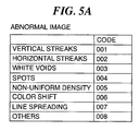
- FIG. 5A is a view showing correspondence between abnormal images and code numbers.
- FIG. 5B is a view showing correspondence between job data items and code numbers.
- FIGS. 6A to 6F are views showing examples of respective data transmission screens.
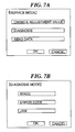
- FIGS. 7A to 7F are views showing examples of respective data transmission screens.
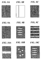
- FIGS. 8A to 8C are views each showing an example of an abnormal image containing vertical streaks.
- FIGS. 9A to 9C are views each showing an example of an abnormal image containing horizontal streaks.
- FIGS. 10A to 10C are views each showing an example of an abnormal image containing white voids.
- FIGS. 11A and 11B are views each showing an example of anabnormal image containing spots.
- FIGS. 12A and 12B are views each showing an example of an abnormal image with a non-uniform density.
- FIG. 13A is a view showing an example of an abnormal image with color shifts.
- FIG. 13B is a view showing an example of an abnormal image with vertical color spreading.
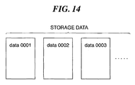
- FIG. 14 is a conceptual view of storage data.
- FIG. 1 is a schematic cross-sectional view useful in explaining an example of an image forming apparatus.
- FIG. 2 is a diagram useful in explaining a maintenance system for image forming apparatuses, according to the embodiment of the present invention.
- FIG. 3 is a block diagram of an image forming apparatus and a host computer.
- FIG. 4 is a view showing an example of supplementary information.
- FIG. 5A is a view showing correspondence between abnormal images and code numbers.
- FIG. 5B is a view showing correspondence between job data items and code numbers.
- FIGS. 6A to 6F and FIGS. 7A to 7F are views showing examples of respective data transmission screens.
- FIGS. 8A to 13B are views showing examples of abnormal images.
- FIG. 14 is a conceptual view of storage data.
- the image forming apparatus 1 is comprised of a printer section 201 and an image reading unit 200.
- the printer section 201 includes a photosensitive drum 10 as an image bearing member rotatably supported therein, and a corona charger 2, developing devices 3y, 3m, 3c, and 3k, and a primary transfer charger 4 arranged around the photosensitive drum 10.
- the developing device 3k is fixedly disposed at a location opposed to the photosensitive drum 10.
- the developing devices 3y, 3m, and 3c form a rotary developing unit, and sequentially move to a location opposed to the photosensitive drum 10.
- the photosensitive drum 10 is driven by a drum motor, not shown, for rotation, and charged by the corona charger 2 to a predetermined potential.
- a laser drive circuit 110 controlled by a CPU 101 performs ON/OFF control of a laser light source 5 such that laser beams are emitted according to image data of an image to be formed.
- a laser beam emitted from the laser light source 5 is irradiated onto the photosensitive drum 10 having a surface thereof uniformly charged, via a polygon mirror 51 and a mirror 52, whereby an electrostatic latent image is formed on the photosensitive drum 10.
- the developing devices 3y, 3m, 3c, and 3k are filled with a predetermined amount of yellow toner, magenta toner, cyan toner, and black toner, respectively, as developers. Whenever the photosensitive drum 10 performs one rotation, the developing devices 3y, 3m, 3c, and 3k develop and visualize latent images formed on the photosensitive drum 10 in the respective colors, as yellow, magenta, cyan, and black toner images, respectively.
- the black developer is formed of a magnetic monocomponent toner, and each of yellow, magenta, and cyan developers is implemented by a two-component developer as a mixture of toner and carrier particles.
- a normal developing method is adopted as a developing method, in which toner reverse in polarity to the charging polarity of the photosensitive drum 10 is applied to a non-exposure part to thereby form an image.
- An intermediate transfer member 50 supported by a driving roller 11, an idle roller 12, and a backup roller 13 is driven by the driving roller 11 for rotation, and at the same time, primary transfer voltage reverse in polarity to the charging polarity of the toner is applied to the primary transfer charger 4 by a high-voltage power supply, not shown.
- the yellow toner image as a first-color image formed on the photosensitive drum 10 is primarily transferred onto the intermediate transfer member 50.
- second-color, third-color, and fourth-color toner images developed on the photosensitive drum 10 are sequentially primarily transferred onto the intermediate transfer member 50, whereby the four toner images are superimposed one upon another to form a color image.
- the primary transfer charger 4 is implemented by a conductive roller (primary transfer roller) formed by covering a metal shaft rod with an elastic layer of conductive rubber or sponge.
- the primary transfer charger 4 is brought into contact with the intermediate transfer member 50, and then the primary transfer voltage is applied to the shaft rod, whereby primary transfer is performed on the intermediate transfer member 50, with the primary transfer charger 4 being rotated along with the rotation of the intermediate transfer member 50.
- toner which was not transferred onto the intermediate transfer member 50 remains on the surface of the photosensitive drum 10.
- the residual toner is moved along with rotation of the photosensitive drum 10 to be removed by a cleaning device 6 and collected in a toner collection container, not shown. After collection of the residual toner, residual charge remaining on the photosensitive drum 10 is removed by a pre-exposure device 16 for a next latent image forming operation.
- the four-color or full-color toner image formed on the intermediate transfer member 50 is secondarily transferred on a sheet P conveyed to a pressure contact nip portion (secondary transfer part) between a secondary transfer roller 14 and the backup roller 13 in a single operation.
- a pressure contact nip portion secondary transfer part
- each of the secondary transfer roller 14 and the backup roller 13 is implemented by a conductive roller.
- the secondary transfer roller 14 is disposed such that it can be brought into contact with and detached from the intermediate transfer member 50.
- the secondary transfer roller 14 is kept away from the intermediate transfer member 50 until a toner image formed by superimposing first to third color toner images has passed through the secondary transfer part, and is thereafter brought into pressure contact with the intermediate transfer member 50.
- the sheet P having the toner image transferred thereon is conveyed to a fixing device 30, where the toner image is subjected to fusion color mixing and is fixed on the sheet P.
- a full-color image is formed on the sheet P.
- Toner remaining on the intermediate transfer member 50 without being transferred onto the sheet is moved along with rotation of the intermediate transfer member 50 to be removed by a cleaning blade 20 and collected in a toner collection container, not shown.
- the cleaning blade 20 is disposed such that it can be brought into contact with and detached from the intermediate transfer member 50.
- the cleaning blade 20 is kept away from the intermediate transfer member 50 until the toner image formed by first to third color toner images has passed the blade position, and is thereafter brought into pressure contact with the intermediate transfer member 50 to clean the residual toner off the same.
- an original 209 placed on an original platen glass 202 is fixedly held on the original platen glass 202 by a presser plate 206, and a scanner unit 207 moves in a direction indicated by an arrow, to optically read an image on the original 209.
- an optical image reflected from the image on the original 209 illuminated by a halogen lamp (or a fluorescent lamp) 203 is formed by on a CCD 205 by a lens 204 and is converted into an electric luminance signal.
- the luminance signal is delivered to a reader image processor 208 and is converted to a digital signal by an A/D converter, not shown, to form an image data signal.
- the image data signal is delivered to the CPU 101 of the printer section 201 to perform ON/OFF control of light emission of the laser light source 5.
- an automatic original feeder and discharger (not shown) so that original feeding can be performed automatically. More specifically, the original may be automatically fed onto the original platen glass 202 by the automatic original feeder and discharger and then subjected to image reading by the scanner unit 207, followed by being automatically discharged onto a discharge tray (not shown).
- a plurality of image forming apparatuses 1 are connected to the host computer (management apparatus) 300 via a network (communication line) 400.
- the image forming apparatuses 1 are installed at respective customer sites and the image forming apparatuses 1 are each managed by an individual responsible service person.
- image data sent to the printer section 201 from the reader image processor 208 is temporarily stored in a memory HDD 105.
- the image data is visually displayed as an image on a display device 102 by the CPU 101 as a controller.
- the display device 102 is implemented by a liquid crystal panel or a CRT and also plays the role of an operating panel having touch-operated keys provided in the display screen.
- Job data indicative of job execution contents configured via the operating panel of the display device 102 are stored in a RAM 108.
- State data indicative of apparatus statuses detected by respective sensors 106 including a temperature and humidity sensor 24 (see FIG. 1) provided in the printer section 201, and the total number of used sheets counted by a sheet counter 107 are sequentially updated and stored in the RAM 108.
- Supplementary information on the image data, the job data, and the state data is sent from a communication device (first transmission unit, second transmission unit) 104 to the host computer 300 via the network 400, together with machine number data as individual identification information on the image forming apparatus 1.
- the host computer 300 is comprised of a CPU 303, a communication device (first reception unit, second reception unit) 301, and an HDD (storage unit) 302.
- the host computer 300 receives data from the image forming apparatuses 1 by the communication device 301 and stores the received data in the HDD 302 to accumulate the same for construction of a database.
- the host computer 300 sends data accumulated in the HDD 302 from the communication device 301 to the image forming apparatus 1 on the requesting side, via the network 400.
- a service person A investigates the cause of the trouble and then carries out repairing work based on the result of the investigation.
- the service person A operates the image forming apparatus 1 to output an image sample of the abnormal image (data of the trouble) in an image pattern in which the features of the abnormality are easily perceivable.
- a sample of an entire halftone image with halftone density all over, a solid image with the maximum density all over, an image with a white background all over, or an image of vertical lines or horizontal lines alone is output.
- These image samples are output in monochrome or full color as required. In the case of color output, only a predetermined one of yellow, magenta, and cyan may be selected and output.
- the double-sided mode and conditions of a sheet used for printout are selected as conditions under which an abnormality is apt to occur, as deemed necessary.
- the sample is output under the same conditions as those of a job which produced an abnormality pointed out by a customer.
- image data and supplementary information on the abnormal image are transmitted by operating an operating screen of the display device 102 of the image forming apparatus 1.
- a predetermined menu screen is operated on the display device 102 to reach a service mode screen shown in FIG. 6A. Then, when an option "SEND DATA" is selected from the service mode screen on the display device 102 and an "OK" key is pressed, the screen is switched to a screen shown in FIG. 6B.
- the screen is switched to a screen shown in FIG. 6C.
- the service person A places on the original platen glass 202 of the image forming apparatus 1 an unused white sheet (plain sheet), without any folds or stains, of the same type as that of a sheet on which the image sample was printed out.
- the white sheet is read in by the image reading unit 200, and the read-in image data is stored in the HDD 105, followed by the screen being switched to a screen shown in FIG. 6D.
- the service person A places on the original platen glass 202 the image sample output from the image forming apparatus 1, and presses an "OK" key. Then, the image sample is read in by the image reading unit 200, and the read-in image data is stored in the HDD 105.
- the CPU 101 computes the difference between the read-in image data of the image sample and that of the white sheet, and the result of the computation is stored again in the HDD 105 as final data of the image sample of the abnormal image.
- the computation of the difference between the read-in image data of the image sample and that of the white sheet is performed so as to prevent disturbance data due to a stain or dirt in the image reading unit 200 or the presser plate 206 from being added to the read-in image data of the image sample. This makes it possible to obtain correct data of the image sample resulting from an abnormality of the printer section 201, if any.
- the CPU 101 calculates the average value of the read-in image data in the entire area on the white sheet and the maximum and minimum values of the same. Then, if the difference between the average value and the maximum value or the difference between the average value and the minimum value is larger than a preset predetermined value, the CPU 101 causes the display device 102 to display a message or the like indicating that an abnormality has occurred in the image reading system due to a stain or dirt or the like.
- the screen shown in FIG. 6E is provided for checking data contents.
- the service person A checks the supplementary information and then inputs comments on the type of the abnormal image, detailed features of the abnormality, and so forth, by using operating keys (not shown) of the image forming apparatus 1.
- the type of an abnormal image is a simplified description of features of an abnormality of the image, and is selected from predetermined abnormality types.
- a data set comprised of the image data and the supplementary information as a set is assigned a serial number "data****".
- the service person A troubleshoots the image forming apparatus 1 that has output the abnormal image.
- the power of the image forming apparatus 1 is kept off during repairing work.
- the power of the image forming apparatus 1 is turned on, and it is confirmed that trouble or inconvenience has been eliminated by the repairing work.
- the predetermined menu screen is operated so as to display a data content confirmation screen, shown in FIG. 6F, on the display device 102.
- an input screen for inputting a repairing method maintenance information
- the service person A inputs a repairing method by using the operating keys (not shown) of the image forming apparatus 1.
- the repairing method is stored in the HDD 105 and added to the data set.
- the data set is sent from the communication device 104 to the host computer 300 via the network 400.
- the host computer 300 receives the data set from the image forming apparatus 1 via the communication device 301 and stores the data in the HDD 302 to accumulate the same for construction of the database.
- Job data is useful information including image sample output conditions, i.e. conditions under which an abnormality is apt to appear in an image.
- the outputs of the respective sensors 106 are each used as data indicative of a status of the image forming apparatus 1 at a time point when an abnormal image is formed.
- the type of an abnormal image, comments, and a repairing method are input by a service person, as mentioned hereinabove.
- the abnormal images are assigned code numbers in advance on a type-by-type basis and the job data items are assigned code numbers on a content-by-content basis. These data items are managed by the code numbers.
- a plurality of data sets are sent to the host computer 300 from the image forming apparatuses 1 in association with a plurality of types of abnormal images, as described above, whereby data of abnormal images and data of repairing methods are accumulated in the HDD 302 of the host computer 300 (see FIG. 14).
- These data items are managed by code numbers, respectively, so that data associated with desired conditions can be retrieved by a machine number or a code number.
- the CPU 303 within the host computer 300 functions as a controller for executing this data retrieval.
- state quantities representing the state of the apparatus are detected by the respective sensors 106, and various image stabilization control operations are carried out based on the results of the detection so as to always maintain image quality in a stable condition against environmental changes and deterioration of component parts due to long-term service.
- a change in electrostatic chargeability or photosensitivity of the photosensitive drum 10 due to long-term service or the stain or dirt on the corona charger 2 causes a change in latent image potential. Therefore, in order to obtain a desired latent image potential, the following method is employed: First, the surface potential of the photosensitive drum 10 is measured by a potential sensor 9 while applying a constant current to the corona charger 2. Then, the potential is measured while sequentially changing the current value of the constant current, to thereby investigate the correlation between the electric current and the potential, and a current value I from which a desired dark potential VD can be obtained is calculated based on the correlation. By applying the current value I during image forming operation, it is possible to always control the dark potential VD to a desired value.
- the photosensitive drum 10 is charged to the dark potential VD based on the result of the above-described calculation, and the potential is measured in this state while sequentially changing the output of the laser light source 5, to thereby investigate the correlation between the laser output and the potential. Then, a laser output P from which the desired light potential VL can be obtained is calculated based on the correlation. By performing exposure by the laser output P during image forming operation, it is possible to always control the light potential VL to a desired value.
- the following method is employed: First, a single-color patch image having a predetermined density is formed in a non-image area on the photosensitive drum 10. Then, the patch image is transferred onto the intermediate transfer member 50, and the density of the patch image is detected by a density sensor 8 disposed in facing relation to the intermediate transfer member 50. Thereafter, the excessive/insufficient amount of the toner is calculated based on the detected density, and if the amount of the toner is insufficient, a time period over which the toner is supplied to the associated developing device is increased to thereby control the density such that it is maintained at a constant level.
- the temperature and humidity sensor 24 is provided in the image forming apparatus 1, and the amount of moisture is calculated based on temperature and humidity detected by the temperature and humidity sensor 24.
- the result of the calculation of the amount of moisture is used to correct the target value of the latent image potential and that of the transfer current. This is because the performance of an electrophotographic image forming apparatus is easily affected by the amount of moisture in an ambient atmosphere, and hence it is required to maintain the optimum performance of the apparatus according to the amount of moisture.
- Each of the developing devices 3y, 3m, and 3c is filled with the two-component developer comprising toner and carrier particles.
- the weight ratio of the amount of toner to the total amount of developer composed of the toner and carrier particles is referred to as toner density.
- the quality of development changes depending on the toner density. As printing operation is continuously performed, toner is progressively consumed, and the toner density becomes lower. When the toner density becomes lower than a predetermined lower limit value, the amount of carrier particles deposited on the photosensitive drum 10 in a developing process increases, which causes a trouble that the carrier particles scratch the cleaning device 6 and the intermediate transfer member 50.
- toner density sensor 7 for monitoring the toner density.
- the toner density sensor 7 is implemented by a photosensor. As shown in FIG. 1, the toner density sensor 7 is disposed at a location opposed to a retracted position of the developing devices 3y, 3m, and 3c, to measure the toner density of developer on a developing roller, not shown, which carries the developer thereon. An output from the toner density sensor 7 is converted to a digital signal to be used as state data indicative of the state of developer.
- the service person B receives data from the host computer 300 so as to obtain information required for repairing work.
- a service mode screen (the same screen as shown in FIG. 6A), shown in FIG. 7A, of the display device 102
- the screen is switched to a diagnosis-mode selection screen shown in FIG. 7B.
- an option "IMAGE” is selected and pressed on the screen, shown in FIG. 7B, so as to carry out image diagnosis, so that the screen is switched to an image diagnosis screen shown in FIG. 7C.
- a selection is made between a search option of "IMAGE SAMPLE” and a search option of "OCCURRENCE MODE". If the search option "IMAGE SAMPLE” is selected and depressed on the screen shown in FIG. 7C, the screen is switched to an image sample retrieval screen shown in FIG. 7D, whereas if the option "OCCURRENCE MODE" is selected and depressed, the screen is switched to an occurrence mode retrieval screen shown in FIG. 7E.
- the CPU 303 retrieves a data set having the code number of vertical streaks from data sets accumulated in the HDD 302. The retrieved data set is sent from the communication device 301 to the image forming apparatus 1 via the network 400.
- the image forming apparatus 1 When the communication device 104 of the image forming apparatus 1 receives the data set sent from the host computer 300, the image forming apparatus 1 stores the data set in the HDD 105 via the CPU 101 and then displays a search result screen shown in FIG. 7F on the display device 102.
- Displayed on the search result screen shown in FIG. 7F are a sample image with vertical streaks, and respective links to supplementary information, a comment box, and a repairing method. If it is desired to view a sample image with another type of vertical streaks on the screen shown in FIG. 7F, a "NEXT SAMPLE" key is selected and pressed. Then, a next data set of a sample image containing vertical streaks having the same code number is retrieved from the HDD 302 in the host computer 300 as in the same way as described above.
- the retrieved data set is sent to the image forming apparatus 1 as in the same way as described above, and the next sample image with vertical streaks is displayed on the search result screen of the display device 102 together with respective links to a supplementary information, a comment box, and a repairing method.
- the service person B retrieves a desired sample image and performs maintenance of the image forming apparatus 1 by referring to a repairing method attached to the sample image (shown by a link in the above-described display screen) most similar to the abnormal image output from the image forming apparatus 1.
- the CPU 303 retrieves a data set satisfying the input conditions from data sets accumulated in the HDD 302, based on job data code numbers.
- the retrieved data set is sent from the communication device 301 to the image forming apparatus 1 via the network 400.
- the image forming apparatus 1 When the communication device 104 of the image forming apparatus 1 receives the data set sent from the host computer 300, the image forming apparatus 1 stores the data sets in the HDD 105 via the CPU 101 and then displays a screen having the same form as that of the search result screen shown in FIG. 7F on the display device 102.
- the service person B compares between the sample image displayed on the screen of the display device 102 and the abnormal image output by the image forming apparatus 1 to be repaired. If the two images have a similarity therebetween, the service person B carries out maintenance of the image forming apparatus 1 by referring to a repairing method attached to the sample image (shown by a link in the above-described display screen). If the two images do not have a similarity, it is possible to retrieve optimum data by repeatedly selecting and pressing the "NEXT SAMPLE" key on the search result screen in the same way as described above until the optimum data is displayed.
- FIGS. 8A to 13B exemplify abnormal images, respectively.
- FIGS. 8A to 8C are views each showing an example of an abnormal image containing vertical streaks.
- FIGS. 9A to 9C are views each showing an example of an abnormal image containing horizontal streaks.
- FIGS. 10A to 10C are views each showing an example of an abnormal image containing white voids.
- FIGS. 11A and 11B are views each showing an example of anabnormal image containing spots.
- FIGS. 12A and 12B are views each showing an example of an abnormal image with a non-uniform density.
- FIG. 13A is a view showing an example of an abnormal image with color shifts.
- FIG. 13B is a view showing an example of an abnormal image with vertical color spreading.
- sample images categorized into the abnormal image containing vertical streaks include a plurality of patterns, shown in FIGS. 8A to 8C, which are different in the color, width, or position of a vertical streak.
- the service person B refers to the sample images of these patterns to thereby retrieve a sample image determined by comparison to be most similar to an abnormal image output by the image forming apparatus 1 to be repaired.
- each of the other types into which other abnormal images are categorized also includes a plurality of patterns. If the service person A refers to the sample images before transmission of data of an abnormal image output from the image forming apparatus 1 to the host computer 300, and finds that a sample image similar to the abnormal image has already been stored in the host computer 300, it is not required to send the abnormal image data to the host computer 300.
- a sample image shown in FIG. 9B can be categorized into the abnormal image containing horizontal streaks and at the same time corresponds to an abnormal image containing white voids shown in FIG. 10C. Therefore, the service person A sends the abnormal image data as data of an abnormal image containing horizontal streaks to the host computer 300, and immediately thereafter sends the same data as data of an abnormal image containing white voids. This enables, when such an abnormal image as shown in FIG. 9B has occurred, the service person B to retrieve a sample image similar to the abnormal image, even by searching only sample images with white voids.
- the image forming apparatus 1 when an abnormal image occurs in an image forming apparatus 1, the image forming apparatus 1 receives a similar one of abnormal images formed in a plurality of image forming apparatuses 1 and an associated piece of supplementary information including a repairing method, which are accumulated in the host computer 300, and displays the retried abnormal image and associated supplementary information including the repairing method on the display device 102. Therefore, even when an exceptional abnormal image occurs in an image forming apparatus 1, a service person can obtain appropriate maintenance information at a customer site by referring to the contents displayed on the display device 102.
- data received from the host computer 300 is displayed on the display device 102 of an image forming apparatus 1, this is not limitative.
- a service person may connect a small potable computer with a display device to the image forming apparatus 1 such that data can be transferred from image forming apparatus 1 to the small computer and displayed on the display device of the small computer.
- the image forming apparatuses 1 of the same model are connected to the host computer 300 via the network 400
- image forming apparatuses of other models may be connected to the network 400.
- the maintenance system is described by way of example which is used for troubleshooting an abnormal image as a trouble, this is not limitative.
- the present invention can be applied to other troubles than an abnormal image, such as forcible stoppage (error) caused by a self-diagnostic function incorporated in an image forming apparatus, or paper jam.
- a computer 500 of a service base may be connected to the host computer 300 via a network 401 such that the abnormal image data and the supplementary information described above can be received by the computer 500.
- a display device 501 may be connected to the computer 500 to display received data, or a printer 502 may be connected to the computer 500 so that image samples of an abnormal image and a supplementary information list can be output from the printer 502 for confirmation.
- a use mode of the system in which when a customer notifies a trouble, he himself sends data of an abnormal image to the host computer 300 from his image forming apparatus 1, and a service person checks the transmitted data on the service base.
- the service person can grasp a repairing method in advance by retrieving a sample image similar to the abnormal image and then visit the customer, and hence, it becomes unnecessary for the service person to retrieve the sample image at the customer site, which enhances maintenance efficiency.
Landscapes
- Engineering & Computer Science (AREA)
- Physics & Mathematics (AREA)
- General Physics & Mathematics (AREA)
- Microelectronics & Electronic Packaging (AREA)
- Multimedia (AREA)
- Signal Processing (AREA)
- Control Or Security For Electrophotography (AREA)
- Facsimiles In General (AREA)
- Accessory Devices And Overall Control Thereof (AREA)
Applications Claiming Priority (1)
| Application Number | Priority Date | Filing Date | Title |
|---|---|---|---|
| JP2006238934A JP4859218B2 (ja) | 2006-09-04 | 2006-09-04 | 画像形成装置のメンテナンスシステムおよびメンテナンス方法 |
Publications (2)
| Publication Number | Publication Date |
|---|---|
| EP1903404A2 true EP1903404A2 (fr) | 2008-03-26 |
| EP1903404A3 EP1903404A3 (fr) | 2008-06-25 |
Family
ID=38924833
Family Applications (1)
| Application Number | Title | Priority Date | Filing Date |
|---|---|---|---|
| EP07017161A Withdrawn EP1903404A3 (fr) | 2006-09-04 | 2007-09-01 | Système de maintenance pour appareil de formation d'images et procédé de maintenance |
Country Status (3)
| Country | Link |
|---|---|
| US (1) | US7773888B2 (fr) |
| EP (1) | EP1903404A3 (fr) |
| JP (1) | JP4859218B2 (fr) |
Cited By (1)
| Publication number | Priority date | Publication date | Assignee | Title |
|---|---|---|---|---|
| NL2023252B1 (en) * | 2019-06-03 | 2020-12-11 | Canon Production Printing Holding Bv | User Interface for a Printer |
Families Citing this family (13)
| Publication number | Priority date | Publication date | Assignee | Title |
|---|---|---|---|---|
| JP4936547B2 (ja) * | 2007-10-19 | 2012-05-23 | キヤノン株式会社 | 監視システム、監視方法、画像処理装置、依頼処理方法、記憶媒体、プログラム |
| US9235819B2 (en) * | 2011-11-04 | 2016-01-12 | Canon Kabushiki Kaisha | Printing system, image forming apparatus, and method |
| EP2835690B1 (fr) * | 2012-04-03 | 2016-12-07 | Canon Kabushiki Kaisha | Dispositif de formation d'image |
| JP6223167B2 (ja) * | 2013-12-18 | 2017-11-01 | キヤノン株式会社 | 画像形成装置および画像診断方法及び画像診断システム |
| JP6020774B1 (ja) * | 2014-12-01 | 2016-11-02 | 東京電力ホールディングス株式会社 | 再利用可否判定方法、限度見本表示装置、および限度見本表示方法 |
| JP6265118B2 (ja) * | 2014-12-26 | 2018-01-24 | 京セラドキュメントソリューションズ株式会社 | 画像形成装置 |
| JP2019174758A (ja) * | 2018-03-29 | 2019-10-10 | 株式会社リコー | 故障診断装置、故障診断方法、故障診断プログラムおよび故障診断システム |
| JP7508893B2 (ja) * | 2019-08-08 | 2024-07-02 | 株式会社リコー | 情報処理装置、情報処理システムおよびプログラム |
| JP7301678B2 (ja) * | 2019-08-30 | 2023-07-03 | キヤノン株式会社 | システム、その制御方法 |
| JP7596672B2 (ja) * | 2020-08-26 | 2024-12-10 | コニカミノルタ株式会社 | 異常対処データ集約システム、異常対処データ集約方法及びプログラム |
| JP7697283B2 (ja) * | 2021-06-16 | 2025-06-24 | コニカミノルタ株式会社 | 画像形成装置 |
| JP7834463B2 (ja) * | 2021-12-13 | 2026-03-24 | キヤノン株式会社 | 画像形成装置、情報処理装置 |
| JP2023157491A (ja) * | 2022-04-15 | 2023-10-26 | 富士フイルムビジネスイノベーション株式会社 | 画像形成装置、プログラムおよび文書の修正方法 |
Citations (7)
| Publication number | Priority date | Publication date | Assignee | Title |
|---|---|---|---|---|
| JPH11136377A (ja) | 1997-10-28 | 1999-05-21 | Sharp Corp | 保守システム |
| JP2000132364A (ja) | 1998-10-27 | 2000-05-12 | Canon Inc | リモートメンテナンスシステム、リモートメンテナンス機器 |
| US20020001475A1 (en) | 2000-05-18 | 2002-01-03 | Kunihiro Kikuchi | Maintenance system and method for performing apparatus management using network |
| US20030088590A1 (en) | 2001-11-02 | 2003-05-08 | Toshiba Tec Kabushiki Kaisha | Method, system and computer program product for providing backup data for use in studying claims |
| US6775238B1 (en) | 1999-07-01 | 2004-08-10 | Ricoh Company, Ltd. | Image forming device management system and method |
| JP2004343621A (ja) | 2003-05-19 | 2004-12-02 | Ricoh Co Ltd | 画像処理装置管理システム |
| JP2006126577A (ja) | 2004-10-29 | 2006-05-18 | Canon Inc | 画像形成システム |
Family Cites Families (6)
| Publication number | Priority date | Publication date | Assignee | Title |
|---|---|---|---|---|
| JPH05114970A (ja) * | 1991-10-23 | 1993-05-07 | Canon Inc | 複写装置 |
| JP2000013518A (ja) * | 1998-06-24 | 2000-01-14 | Ricoh Co Ltd | 画像形成装置管理システム |
| JP2002084388A (ja) | 2000-09-07 | 2002-03-22 | Canon Inc | 画像形成装置及びその管理方法 |
| JP3610323B2 (ja) * | 2001-07-27 | 2005-01-12 | キヤノン株式会社 | 診断装置、診断方法、画像形成装置、制御方法、記憶媒体並びにプログラム |
| JP4356276B2 (ja) * | 2001-09-10 | 2009-11-04 | コニカミノルタビジネステクノロジーズ株式会社 | 画像形成システムにおけるメンテナンス方法、および当該画像形成システムにおける画像形成装置 |
| JP2003099234A (ja) * | 2001-09-25 | 2003-04-04 | Brother Ind Ltd | 電子機器及びそのサービスサポートシステム |
-
2006
- 2006-09-04 JP JP2006238934A patent/JP4859218B2/ja not_active Expired - Fee Related
-
2007
- 2007-08-31 US US11/848,888 patent/US7773888B2/en not_active Expired - Fee Related
- 2007-09-01 EP EP07017161A patent/EP1903404A3/fr not_active Withdrawn
Patent Citations (7)
| Publication number | Priority date | Publication date | Assignee | Title |
|---|---|---|---|---|
| JPH11136377A (ja) | 1997-10-28 | 1999-05-21 | Sharp Corp | 保守システム |
| JP2000132364A (ja) | 1998-10-27 | 2000-05-12 | Canon Inc | リモートメンテナンスシステム、リモートメンテナンス機器 |
| US6775238B1 (en) | 1999-07-01 | 2004-08-10 | Ricoh Company, Ltd. | Image forming device management system and method |
| US20020001475A1 (en) | 2000-05-18 | 2002-01-03 | Kunihiro Kikuchi | Maintenance system and method for performing apparatus management using network |
| US20030088590A1 (en) | 2001-11-02 | 2003-05-08 | Toshiba Tec Kabushiki Kaisha | Method, system and computer program product for providing backup data for use in studying claims |
| JP2004343621A (ja) | 2003-05-19 | 2004-12-02 | Ricoh Co Ltd | 画像処理装置管理システム |
| JP2006126577A (ja) | 2004-10-29 | 2006-05-18 | Canon Inc | 画像形成システム |
Cited By (1)
| Publication number | Priority date | Publication date | Assignee | Title |
|---|---|---|---|---|
| NL2023252B1 (en) * | 2019-06-03 | 2020-12-11 | Canon Production Printing Holding Bv | User Interface for a Printer |
Also Published As
| Publication number | Publication date |
|---|---|
| EP1903404A3 (fr) | 2008-06-25 |
| JP2008061187A (ja) | 2008-03-13 |
| US7773888B2 (en) | 2010-08-10 |
| US20080056736A1 (en) | 2008-03-06 |
| JP4859218B2 (ja) | 2012-01-25 |
Similar Documents
| Publication | Publication Date | Title |
|---|---|---|
| US7773888B2 (en) | Image forming apparatus maintenance via error transmission | |
| US5303005A (en) | Image forming apparatus with improved maintenance control | |
| US5243382A (en) | Image forming apparatus capable of efficient maintenance work | |
| CN102608899B (zh) | 具有设定维护方式的功能的图像形成装置 | |
| JP2008102470A (ja) | 画像形成装置および画像形成方法 | |
| US20120065885A1 (en) | Maintenance support device and image forming system | |
| EP0913737A2 (fr) | Appareil de formation d'images et appareil de recyclage pour recycler d'un unité de formation d'images | |
| US5949553A (en) | Image forming apparatus having remote maintenance function and method of remote maintenance | |
| JP4933167B2 (ja) | 診断システム | |
| JP3180811B2 (ja) | 画像形成装置の保守管理用携帯装置 | |
| JPH03196053A (ja) | 画像形成装置 | |
| US20090220255A1 (en) | Maintenance unit and maintenance method of image forming apparatus | |
| US12235603B2 (en) | Replacing photoconductor drums associated with image forming apparatuses | |
| JP2780348B2 (ja) | 画像形成装置 | |
| US7089153B2 (en) | Replaceable component management tool | |
| JP7551386B2 (ja) | 画像形成装置、画像形成装置の制御方法、プログラム、及び管理システム | |
| JP2780347B2 (ja) | 画像形成装置 | |
| JPH03226772A (ja) | 画像形成装置管理システム | |
| JP2021039267A (ja) | 寿命判定装置、寿命判定方法および寿命判定プログラム | |
| JP2019101238A (ja) | 画像形成装置、画像形成システム及び制御電極の診断方法 | |
| JP3019348B2 (ja) | 画像形成装置管理システム | |
| JP2011164398A (ja) | 画像形成装置、画像形成方法、制御プログラム及び記録媒体 | |
| JP2867517B2 (ja) | 画像形成装置 | |
| JPH03226766A (ja) | 画像形成装置管理システム | |
| JP2025097342A (ja) | 画像形成システム、情報管理方法及びプログラム |
Legal Events
| Date | Code | Title | Description |
|---|---|---|---|
| PUAI | Public reference made under article 153(3) epc to a published international application that has entered the european phase |
Free format text: ORIGINAL CODE: 0009012 |
|
| AK | Designated contracting states |
Kind code of ref document: A2 Designated state(s): AT BE BG CH CY CZ DE DK EE ES FI FR GB GR HU IE IS IT LI LT LU LV MC MT NL PL PT RO SE SI SK TR |
|
| AX | Request for extension of the european patent |
Extension state: AL BA HR MK YU |
|
| PUAL | Search report despatched |
Free format text: ORIGINAL CODE: 0009013 |
|
| AK | Designated contracting states |
Kind code of ref document: A3 Designated state(s): AT BE BG CH CY CZ DE DK EE ES FI FR GB GR HU IE IS IT LI LT LU LV MC MT NL PL PT RO SE SI SK TR |
|
| AX | Request for extension of the european patent |
Extension state: AL BA HR MK RS |
|
| 17P | Request for examination filed |
Effective date: 20081229 |
|
| AKX | Designation fees paid |
Designated state(s): DE FR GB |
|
| 17Q | First examination report despatched |
Effective date: 20090310 |
|
| STAA | Information on the status of an ep patent application or granted ep patent |
Free format text: STATUS: THE APPLICATION HAS BEEN WITHDRAWN |
|
| 18W | Application withdrawn |
Effective date: 20170630 |