EP1903499A2 - Radiologisches Bilderfassungssystem und radiologisches Bilderfassungsverfahren - Google Patents
Radiologisches Bilderfassungssystem und radiologisches Bilderfassungsverfahren Download PDFInfo
- Publication number
- EP1903499A2 EP1903499A2 EP07116212A EP07116212A EP1903499A2 EP 1903499 A2 EP1903499 A2 EP 1903499A2 EP 07116212 A EP07116212 A EP 07116212A EP 07116212 A EP07116212 A EP 07116212A EP 1903499 A2 EP1903499 A2 EP 1903499A2
- Authority
- EP
- European Patent Office
- Prior art keywords
- image
- subject
- radiological
- radiological image
- detecting device
- Prior art date
- Legal status (The legal status is an assumption and is not a legal conclusion. Google has not performed a legal analysis and makes no representation as to the accuracy of the status listed.)
- Withdrawn
Links
Images



Classifications
-
- G—PHYSICS
- G06—COMPUTING OR CALCULATING; COUNTING
- G06T—IMAGE DATA PROCESSING OR GENERATION, IN GENERAL
- G06T5/00—Image enhancement or restoration
- G06T5/73—Deblurring; Sharpening
-
- A—HUMAN NECESSITIES
- A61—MEDICAL OR VETERINARY SCIENCE; HYGIENE
- A61B—DIAGNOSIS; SURGERY; IDENTIFICATION
- A61B6/00—Apparatus or devices for radiation diagnosis; Apparatus or devices for radiation diagnosis combined with radiation therapy equipment
- A61B6/52—Devices using data or image processing specially adapted for radiation diagnosis
- A61B6/5258—Devices using data or image processing specially adapted for radiation diagnosis involving detection or reduction of artifacts or noise
-
- G—PHYSICS
- G06—COMPUTING OR CALCULATING; COUNTING
- G06T—IMAGE DATA PROCESSING OR GENERATION, IN GENERAL
- G06T5/00—Image enhancement or restoration
- G06T5/10—Image enhancement or restoration using non-spatial domain filtering
-
- A—HUMAN NECESSITIES
- A61—MEDICAL OR VETERINARY SCIENCE; HYGIENE
- A61B—DIAGNOSIS; SURGERY; IDENTIFICATION
- A61B6/00—Apparatus or devices for radiation diagnosis; Apparatus or devices for radiation diagnosis combined with radiation therapy equipment
- A61B6/58—Testing, adjusting or calibrating thereof
- A61B6/588—Setting distance between source unit and detector unit
-
- A—HUMAN NECESSITIES
- A61—MEDICAL OR VETERINARY SCIENCE; HYGIENE
- A61B—DIAGNOSIS; SURGERY; IDENTIFICATION
- A61B6/00—Apparatus or devices for radiation diagnosis; Apparatus or devices for radiation diagnosis combined with radiation therapy equipment
- A61B6/58—Testing, adjusting or calibrating thereof
- A61B6/589—Setting distance between source unit and patient
-
- G—PHYSICS
- G06—COMPUTING OR CALCULATING; COUNTING
- G06T—IMAGE DATA PROCESSING OR GENERATION, IN GENERAL
- G06T2207/00—Indexing scheme for image analysis or image enhancement
- G06T2207/10—Image acquisition modality
- G06T2207/10116—X-ray image
-
- G—PHYSICS
- G06—COMPUTING OR CALCULATING; COUNTING
- G06T—IMAGE DATA PROCESSING OR GENERATION, IN GENERAL
- G06T2207/00—Indexing scheme for image analysis or image enhancement
- G06T2207/20—Special algorithmic details
- G06T2207/20048—Transform domain processing
- G06T2207/20056—Discrete and fast Fourier transform, [DFT, FFT]
-
- G—PHYSICS
- G06—COMPUTING OR CALCULATING; COUNTING
- G06T—IMAGE DATA PROCESSING OR GENERATION, IN GENERAL
- G06T2207/00—Indexing scheme for image analysis or image enhancement
- G06T2207/30—Subject of image; Context of image processing
- G06T2207/30004—Biomedical image processing
Definitions
- the present invention relates to a radiological image capturing system and a radiological image capturing method for capturing a radiological image of a subject by irradiating radial rays onto the subject.
- Patent Document 1 JP-2509181 , Japanese Patent Gazette sets forth a radiological image capturing system that includes the steps of: compensating for the Point Spread Function representing the distribution of the X rays scattered on the surface of the detector with respect to the incident X rays penetrated into the subject, corresponding to the radiographing conditions of the X ray original image, so as to output the filter coefficients; finding the scattered X ray image by convoluting the filter coefficients and the X ray original image with each other; and subtracting the scattered X ray image from the X ray original image so as to directly obtain the X ray image.
- Patent Document 2 JP-3423828 , Japanese Patent Gazette sets forth another radiological image capturing system that includes the steps of: finding the intensity distribution function of the scattered light from the product of the intensity ratio of the scattered light and the Point Spread Function of the scattered light in the state of placing no subject, so as to calculate the image of the scattered light component; finding the intensity distribution function of the scattered rays from the product of the Point Spread Function of the scattered rays and the intensity ratio, derived from the subject image and the radiographing condition, in the state of placing the human dummy subject having a uniform thickness, so as to calculate the image of the scattered ray component; and subtracting the image of the scattered light component and the image of the scattered ray component from the image of the above subject, so as to restore the X ray image in the degraded image restoration mode.
- At least one of the objects of the present invention can be attained by any one of the radiological image capturing systems and the radiological image capturing methods described as follows.
- Fig. 1 shows a schematic diagram of an overall configuration of a radiological image capturing system 1 embodied in the present invention.
- the radiological image capturing system 1 is constituted by a radiographing apparatus 2 to capture an X ray image of a subject H and an image processing apparatus 3 to conduct various kinds of image processing, in order to capture the X ray image by irradiating X rays onto the subject H and to apply the image processing, such as a degraded image restoration processing, etc., to the X ray image captured by the radiographing apparatus 2.
- the scope of the radial rays is not limited to the X rays, but any one of gamma rays, electron rays, etc., is also applicable in the present invention.
- the radiographing apparatus 2 is provided with an X ray tube 4, serving as a source of radial rays, an image capturing section 5 and a control apparatus 6, and is so constituted that the X ray image of the subject H, fixed at a predetermined position by a fixing member 7, can be captured.
- the fixing member 7 is made of a material, such as a resin, etc., through which the radial rays can penetrate.
- the X ray tube 4 is equipped at a position located in the backside space of the subject H, and generates X rays having a predetermined focusing aperture so as to irradiate the radial rays towards the subject H.
- the image capturing section 5 is equipped at a position located in a front side space of the subject H, in such a manner that the height of the image capturing section 5 can be adjusted according to a current photographing portion, serving as a diagnosis object. Further, the image capturing section 5 incorporates an image detecting device 5a.
- the image detecting device 5a is configured to detect the X rays irradiated onto its detecting surface.
- the image capturing section 5 is provided with a reading section (not shown in the drawings) that irradiates an excitation light, such as a laser beam, etc., onto the stimulable phosphor plate so as to electro-photographically convert the stimulated light emitted from the stimulable phosphor plate to image signals.
- This image signals (analogue signals) generated by the reading section are outputted to the control apparatus 6.
- the FPD is configured by aligning conversion elements, each of which generates an electric signal having an intensity corresponding to the amount of the incident X ray, into a matrix pattern, and differs from the stimulable phosphor plate on the point that the electric signals are directly generated within the FPD.
- an analogue-to-digital converter (not shown in the drawings) converts the analogue electric signals, generated in the FPD, to digital image data, which are outputted to the control apparatus 6.
- the image detecting device 5a is positioned so as to fulfill the condition represented by the formula (1) shown as follow.
- R1 distance between the X ray tube 4 and the predetermined position of the subject H fixed by the fixing member 7, for instance, a position at which the subject H contacts the fixing member 7 (subject reference position HB)
- R2 distance between the subject reference position HB and a detecting surface 5H of the image detecting device 5a
- D ( ⁇ m) focusing aperture of the X ray tube 4
- A constant value equal to or greater than 0.05.
- the system is so constituted that the accurate X ray radiological image can be obtained by applying the degraded image restoration processing, which employs a single image restoration parameter, irrespective of the position of the diagnosis object in the thickness direction of the subject H.
- the reason why the accurate X ray radiological image can be obtained by applying the degraded image restoration processing, which employs a single image restoration parameter, irrespective of the position of the diagnosis object in the thickness direction of the subject H, when the image detecting device 5a and the fixing member 7 are disposed at such positions that fulfills the formula (1) mentioned in the above, will be detailed in the following.
- Fig. 2 shows a plane view schematically indicating the positional relationship between the X ray tube 4, the subject H and the image detecting device 5a in the radiographing apparatus 2 shown in Fig. 1.
- the subject H contacts the fixing member 7 at the subject reference position HB being apart from the detecting surface 5H of the image detecting device 5a.
- a gap distance between a first diagnosis object position and a second diagnosis object position which is apart from the image detecting device 5a by a distance farther than that of the first diagnosis object position, is equal to or shorter than 300 mm.
- a position deviating toward the X ray tube 4 from the subject reference position HB by 10 mm is defined as a diagnosis object position P
- another position deviating toward the X ray tube 4 from the subject reference position HB by 310 mm is defined as a diagnosis object position Q.
- the diagnosis object position P is made to deviate from the subject reference position HB by 10 mm, while the gap distance between the diagnosis object position P and the diagnosis object position Q is established at 300 mm in the present embodiment.
- Fig. 3 shows a graph indicating transitions of ratio of blurs between the point spread distribution ⁇ 1 of the radiological image ⁇ and the point spread distribution ⁇ 2 of the radiological image ⁇ , corresponding to the variation of R2 in the example shown in Fig. 2.
- the focusing aperture D of the X ray tube 4 is set at 100 ⁇ m, while the value of R1 is sequentially changed to 0.65, 1.0 and 2.0 m (meters).
- Fig. 4 shows a graph indicating transitions of ratio of blurs between the point spread distribution ⁇ 1 of the radiological image ⁇ and the point spread distribution ⁇ 2 of the radiological image ⁇ , corresponding to the variation of the focusing aperture D, with respect to different values of R2, which represents a distance from the subject reference position HB to the detecting surface 5H.
- ratio of blurs between the X ray radiological images of the radiological image ⁇ and the radiological image ⁇ varies in substantially a linear relationship with the common logarithms of the focusing aperture D.
- the difference between blurs is set at a small value to such a extent that the difference between blurs of the X ray radiological images can be ignored by fulfilling the formula (1).
- the degraded image restoration processing which employs a single image restoration parameter, irrespective of the position of the diagnosis object in the thickness direction of the subject H.
- the constant value A is set at a value being equal to or greater than 2.0, since it becomes possible to reduce the ratio of blurs, indicated in the example shown in Fig.
- the X ray tube 4 and the image capturing section 5 are electrically coupled to the control apparatus 6. Further, the image processing apparatus 3 is also electrically coupled to the control apparatus 6.
- the radiological image capturing system 1 is constituted by the radiographing apparatus 2 and the image processing apparatus 3, while the radiographing apparatus 2 is provided with the control apparatus 6.
- the control apparatus 6 is electrically coupled to each of the X ray tube 4 and the image capturing section 5, and is provided with an operating section 6a to conduct controlling operations of the X ray tube 4 and the image capturing section 5, a processing section 6b to conduct various kinds of signal processing and data processing operations, such as a data conversion processing for converting analogue image signals to digital image data, etc., a control section 6c to concentrically control each of the sections of the radiographing apparatus 2 and a communication section 6d to conduct communicating operations with the other external apparatuses.
- the image processing apparatus 3 is provided with an inputting section 3a to input the image data (either the analogue image signals or the digital image data) read by the image detecting device 5a of the image capturing section 5, an operating section 3b to input various kinds of instructions, a control section 3c to control each of the structural sections of the image processing apparatus 3, a storage section 3d to store various kinds of control data and image data, an image processing section 3e to apply image processing to the image data based on the control data stored in the storage section 3d and a display section 3f to display an image based on the processed image data to which the image processing is already applied by the image processing section 3e.
- an inputting section 3a to input the image data (either the analogue image signals or the digital image data) read by the image detecting device 5a of the image capturing section 5, an operating section 3b to input various kinds of instructions, a control section 3c to control each of the structural sections of the image processing apparatus 3, a storage section 3d to store various kinds of control data and image data, an image processing
- the inputting section 3a is electrically coupled to the communication section 6d of the radiographing apparatus 2, so as to input the image data read by the image detecting device 5a.
- the operating section 3b includes a mouse, a keyboard or an operation panel employing a touch panel method, etc., which are generally well-known parts, so as to make it possible for the user to input instructions in regard to the image processing operations.
- the control section 3c includes a CPU (Central Processing Unit), a RAM (Random Access Memory), etc., and reads out various kinds of controlling programs stored in the storage section 3d in advance and develops them into the RAM, so as to conducts various kinds of arithmetic calculations and concentrically control each of the structural sections by executing the abovementioned controlling programs.
- a CPU Central Processing Unit
- RAM Random Access Memory
- control section 3c serves as an image restoration parameter creating section that conducts a calculation processing of the Point Spread Function (PSF) to be stored in the storage section 3d, based on a reference radiological image of the subject radiographed by the radiographing apparatus 2, namely, an image restoration parameter creation processing.
- the Point Spread Function (PSF) is defined as a function to be employed in the degraded image restoration processing in regard to the blurred image.
- the reference radiological image is defined as such a radiological image that is located at a predetermined position in the thickness direction of the subject H and is employed in the calculating operation of the Point Spread Function (PSF).
- the calculating operation of the PSF is implemented at a certain appropriate time before radiographing the subject (for instance, at the time when installing the apparatus, the time when conducting the maintenance operations, the time when changing the X ray tube 4 or the inputting section 3a, etc.).
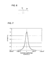
- the calculating operation of the PSF is implemented, for instance, in such a state that a plate member 8a (shading member) on which a through hole 8b is formed at a predetermined position, as shown in Fig. 6, is equipped in the radiographing apparatus 2.
- the plate member 8a being applicable to the above, is made of a radial ray shading material, such as a lead, etc., having the through hole 8b formed at a center of the plate, as shown in Fig. 6.
- the thickness of the plate member 8a is set at a value in a range of 0.01 - 0.1 mm, while the diameter of the through hole 8b is set at a value in a range of several - 50 ⁇ m.
- the control section 3c controls the X ray tube 4 and the image capturing section 5 of the radiographing apparatus 2 so as to radiograph the through hole 8b of the plate member 8a. Further, when the X ray radiological image data acquired by the image capturing section 5 are inputted into the inputting section 3a as the reference radiological image data, the control section 3c creates the luminance distribution from the reference radiological image data, so as to create a function being approximate to a linear shape of the luminance distribution.
- This function created in the above is the Point Spread Function (PSF) at each diagnosis object position of the diagnosis object concerned.
- the created PSF is stored in the storage section 3d as the image restoration parameter.
- the PSF is a distribution function shown in Fig. 7.
- the horizontal axis represents deviation amounts on the detecting surface 5H of the image detecting device 5a when the center position of the through hole 8b is set at zero
- the vertical axis represents the PSF when a maximum intensity of the radial rays, to be detected at the deviation amount of zero, is set at 1.0.
- the PSF shown in Fig. 7 is calculated on the basis of the reference radiological image data on the conditions that the focusing aperture D of the X ray tube 4 is set at 500 ⁇ m, the distance from the X ray tube 4 to the image detecting device 5a is set at 900 mm and the diameter of the through hole 8b set at 10 ⁇ m.
- the PSF only corresponding to the blurs caused by the focusing aperture D is employed in the present embodiment, it is also applicable that the PSF including other blurs caused by the scattered radial rays, which are scattered within the subject, in addition to the blurs caused by the focusing aperture D, is employed for the degraded image restoration processing.
- the storage section 3d stores various kinds of programs to be executed by the control section 3c, image processing programs to be executed by the image processing section 3e, parameters and data necessary for executing the above programs, etc. in it. Further, the storage section 3d employed in the present embodiment also stores the X ray radiological image data representing the radiological image captured by the radiographing apparatus 2 with the radiographing conditions, and, for instance, the PSF as the image restoration parameter, in it.
- the image processing section 3e applies the degraded image restoration processing, which employs a predetermined PSF as the image restoration parameter, to the X ray radiological image data representing the radiological image captured by the radiographing apparatus 2.
- the image processing section 3e reads out the predetermined PSF, correlated to the radiographing conditions, from the storage section 3d, so as to create a degradation restored image from the image restoration parameter based on the PSF concerned and the image data stored in the storage section 3d.
- the image detecting device 5a and the fixing member 7 at such the positions that fulfill the aforementioned formula (1), since the differences between blurs become small to such the extent that the differences between blurs can be ignored, the accurate X ray radiological image can be obtained by applying the degraded image restoration processing, which employs a single image restoration parameter, irrespective of the position of the diagnosis object in the thickness direction of the subject H.
- the image processing section 3e also conducts other kind of image processing, such as a gradation correction processing, etc.
- the degraded image restoration processing conducted by the image processing section 3e is to acquire the degradation restored image by deconvoluting the X ray radiological image data inputted from the inputting section 3a with the PSF serving as the image restoration parameter.
- the image processing section 3e applies the Fourier Transform processing to the X ray radiological image data inputted from the inputting section 3a, while reads out the predetermined PSF correlated to the radiographing conditions from the storage section 3d and also applies the Fourier Transform processing to the predetermined PSF, so as to create the degradation restored image by subtracting the Fourier-Transformed PSF from the Fourier-Transformed X-ray radiological image data.
- the display section 3f is provided with a display device, so as to display the image represented by the X ray radiological image data after image processing are applied and various kinds of displaying screens on the display device.
- the user fixes the subject H onto the fixing member 7, so that the values of R1 and R2 fulfill the condition of the formula (1) aforementioned.
- R2 ⁇ 0.15 m, R2 ⁇ 0.10 m, R2 ⁇ 0.05 m respectively corresponding to the value of R1.
- the user installs the plate member 8a, so that the position of the through hole 8b of the plate member 8a coincides with any one of the diagnosis object positions.
- the control section 3c controls the X ray tube 4 and the image capturing section 5 of the radiographing apparatus 2, so as to radiograph the image of the through hole 8b of the plate member 8a.
- the image capturing section 5 outputs the acquired reference radiological image data, which are inputted into the image processing apparatus 3 through the inputting section 3a (reference radiological image inputting process).
- control section 3c creates the luminance distribution from the reference radiological image data inputted from the inputting section 3a, so as to create a function being approximate to a linear shape of the luminance distribution, namely, the Point Spread Function (PSF) at each diagnosis object position of the diagnosis object concerned. Further, the control section 3c stores the created PSF into the storage section 3d as the image restoration parameter.
- PSF Point Spread Function
- the image detecting device 5a of the image capturing section 5 detects the irradiated X rays.
- energy of the X rays are accumulated into the stimulable phosphor plate.
- the reading section (not shown in the drawings) irradiates the excitation light onto the stimulable phosphor plate so as to electro-photographically convert the stimulated light emitted from the stimulable phosphor plate to image signals, so as to output the generated image signals (analogue signals) to the control apparatus 6.
- an analogue-to-digital converter (not shown in the drawings) converts the analogue electric signals, generated in the FPD, to digital image data, so as to output the digital image data, acquired by the analogue-to-digital converting operation, to the control apparatus 6.
- the communication section 6d of the control apparatus 6 transmits the X ray radiological image data acquired in the image capturing section 5 to the image processing apparatus 3.
- the storage section 3d stores the X ray radiological image data associated with the radiographing conditions in it.
- Fig. 8 shows a flowchart indicating the image processing to be conducted by the image processing section 3e.
- the flowchart of the image processing to be conducted by the image processing section 3e includes the steps of: inputting the X ray radiological image data from the inputting section 3a under the controlling operation of the control section 3c (Step S1); applying the Fourier Transform processing to the X ray radiological image data inputted in the above step (Step S2); reading out the predetermined PSF correlated to the radiographing condition from the storage section 3d (Step S3); applying the Fourier Transform processing to the PSF read out in the above step (Step S4); subtracting the Fourier Transformed PSF processed in Step S4 from the Fourier-Transformed X-ray radiological image data processed in Step S3 (Step S5), so as to generate calculated differential image data; applying the Reverse Fourier Transform processing to the calculated differential image data derived in Step
- control section 3c controls the display section 3f so as to display the X ray radiological image represented by the degradation restored image data, generated according to the abovementioned process by the image processing section 3e, on its screen.
- the radiological image capturing system 1 and the radiological image capturing method, embodied in the present invention as described in the foregoing, when the radiographing operation is conducted in such a state that the subject H is fixed at the predetermined position so as to fulfill the formula (1) aforementioned, the ratio of blurs is reduced to a smaller value to such an extent that the difference of blurs in the radiographed images with respect to each diagnosis object can be ignored. Accordingly, irrespective of the position of the diagnosis object in the thickness direction of the subject H, it becomes possible to obtain the accurate X ray radiological image, by applying the degraded image restoration processing, which employs only a single image restoration parameter.
- the gap distance between the first diagnosis object position Pnd the second diagnosis object position is equal to or smaller than 300 mm, it becomes possible to apply the degraded image restoration processing, in which only a single image restoration parameter is employed, to the radiological image concerned without causing any practical problem, irrespective of the position of the diagnosis object in the thickness direction of the subject H.
- the image restoration parameter is created on the basis of the reference radiological image of the subject radiographed by the radiographing apparatus 2, it becomes possible to create the restored image corresponding to the individual differences of the X ray tube 4 and/or the image detecting device 5a.
- the radiological image capturing system and the radiological image capturing method, embodied in the present invention it becomes possible to obtain a radiological image, being more accurate than ever, by employing a simple and easy processing, irrespective of the position of the diagnosis object in the thickness direction of the subject H.
Landscapes
- Engineering & Computer Science (AREA)
- Physics & Mathematics (AREA)
- Health & Medical Sciences (AREA)
- Life Sciences & Earth Sciences (AREA)
- Medical Informatics (AREA)
- Theoretical Computer Science (AREA)
- General Physics & Mathematics (AREA)
- Biomedical Technology (AREA)
- Animal Behavior & Ethology (AREA)
- Optics & Photonics (AREA)
- Pathology (AREA)
- Radiology & Medical Imaging (AREA)
- High Energy & Nuclear Physics (AREA)
- Heart & Thoracic Surgery (AREA)
- Molecular Biology (AREA)
- Surgery (AREA)
- Nuclear Medicine, Radiotherapy & Molecular Imaging (AREA)
- General Health & Medical Sciences (AREA)
- Public Health (AREA)
- Veterinary Medicine (AREA)
- Biophysics (AREA)
- Computer Vision & Pattern Recognition (AREA)
- Apparatus For Radiation Diagnosis (AREA)
- Image Processing (AREA)
- Image Analysis (AREA)
Applications Claiming Priority (1)
| Application Number | Priority Date | Filing Date | Title |
|---|---|---|---|
| JP2006257762A JP2008073342A (ja) | 2006-09-22 | 2006-09-22 | 放射線画像撮影システム及び放射線画像撮影方法 |
Publications (2)
| Publication Number | Publication Date |
|---|---|
| EP1903499A2 true EP1903499A2 (de) | 2008-03-26 |
| EP1903499A3 EP1903499A3 (de) | 2009-08-12 |
Family
ID=38895813
Family Applications (1)
| Application Number | Title | Priority Date | Filing Date |
|---|---|---|---|
| EP07116212A Withdrawn EP1903499A3 (de) | 2006-09-22 | 2007-09-12 | Radiologisches Bilderfassungssystem und radiologisches Bilderfassungsverfahren |
Country Status (4)
| Country | Link |
|---|---|
| US (1) | US20080073567A1 (de) |
| EP (1) | EP1903499A3 (de) |
| JP (1) | JP2008073342A (de) |
| CN (1) | CN101147682A (de) |
Families Citing this family (9)
| Publication number | Priority date | Publication date | Assignee | Title |
|---|---|---|---|---|
| JP2008073208A (ja) * | 2006-09-21 | 2008-04-03 | Konica Minolta Medical & Graphic Inc | 画像処理装置及び画像処理方法 |
| CN101668702A (zh) * | 2007-04-26 | 2010-03-10 | 东亚合成株式会社 | 水滑石化合物及其制造方法、无机离子捕捉剂、组合物、电子部件密封用树脂组合物 |
| CN102369458A (zh) * | 2009-04-03 | 2012-03-07 | 株式会社岛津制作所 | 放射线检测器以及具备该放射线检测器的放射线摄影装置 |
| WO2011035513A1 (zh) | 2009-09-28 | 2011-03-31 | Cao Hongguang | 一种x射线图像探测装置 |
| JP5595184B2 (ja) * | 2010-08-26 | 2014-09-24 | 富士フイルム株式会社 | 放射線画像撮影装置および放射線画像撮影方法 |
| JP6256941B2 (ja) * | 2013-10-17 | 2018-01-10 | 国立大学法人大阪大学 | X線撮像方法及びx線撮像装置 |
| AU2014250719A1 (en) * | 2014-10-17 | 2016-05-05 | Canon Kabushiki Kaisha | Image processing method, system and apparatus |
| JP6855406B2 (ja) * | 2018-03-23 | 2021-04-07 | 富士フイルム株式会社 | 画像処理装置、放射線画像撮影システム、画像処理方法、及び画像処理プログラム |
| JP7593000B2 (ja) * | 2019-11-27 | 2024-12-03 | 株式会社リコー | 信号分離装置、プログラムおよび信号分離方法 |
Family Cites Families (10)
| Publication number | Priority date | Publication date | Assignee | Title |
|---|---|---|---|---|
| US4947323A (en) * | 1986-05-22 | 1990-08-07 | University Of Tennessee Research Corporation | Method and apparatus for measuring small spatial dimensions of an object |
| US5414782A (en) * | 1992-12-16 | 1995-05-09 | The United States Of Amercia As Represented By The Secretary Of Commerce | Procedure for digital image restoration |
| JP3423828B2 (ja) * | 1995-11-30 | 2003-07-07 | 株式会社日立メディコ | X線画像作成方法およびその装置 |
| US6928182B1 (en) * | 1998-10-15 | 2005-08-09 | Kui Ming Chui | Imaging |
| JP4389371B2 (ja) * | 2000-09-28 | 2009-12-24 | 株式会社ニコン | 画像修復装置および画像修復方法 |
| US6895077B2 (en) * | 2001-11-21 | 2005-05-17 | University Of Massachusetts Medical Center | System and method for x-ray fluoroscopic imaging |
| US6862337B2 (en) * | 2003-06-25 | 2005-03-01 | General Electric Company | Linear track based digital tomosynthesis system and method |
| JP2005351736A (ja) * | 2004-06-10 | 2005-12-22 | Matsushita Electric Ind Co Ltd | X線画像鮮鋭化処理方法、及びx線画像撮像装置 |
| US7215732B2 (en) * | 2004-09-30 | 2007-05-08 | General Electric Company | Method and system for CT reconstruction with pre-correction |
| US20070206847A1 (en) * | 2006-03-06 | 2007-09-06 | Heumann John M | Correction of vibration-induced and random positioning errors in tomosynthesis |
-
2006
- 2006-09-22 JP JP2006257762A patent/JP2008073342A/ja active Pending
-
2007
- 2007-09-12 EP EP07116212A patent/EP1903499A3/de not_active Withdrawn
- 2007-09-17 US US11/901,476 patent/US20080073567A1/en not_active Abandoned
- 2007-09-18 CN CN200710152862.6A patent/CN101147682A/zh active Pending
Also Published As
| Publication number | Publication date |
|---|---|
| EP1903499A3 (de) | 2009-08-12 |
| US20080073567A1 (en) | 2008-03-27 |
| CN101147682A (zh) | 2008-03-26 |
| JP2008073342A (ja) | 2008-04-03 |
Similar Documents
| Publication | Publication Date | Title |
|---|---|---|
| EP1903499A2 (de) | Radiologisches Bilderfassungssystem und radiologisches Bilderfassungsverfahren | |
| US7418078B2 (en) | Spot-size effect reduction | |
| US7346204B2 (en) | Method of and apparatus for generating phase contrast image | |
| JP5384521B2 (ja) | 放射線撮像装置 | |
| US4947323A (en) | Method and apparatus for measuring small spatial dimensions of an object | |
| US9949699B2 (en) | Tomographic image generating system comprising a three-dimensional camera for aquiring a thickness and/or a two-dimensional shape of a surface of a subject | |
| US5878108A (en) | Method for generating X-ray image and apparatus therefor | |
| US8009892B2 (en) | X-ray image processing system | |
| EP3342342A1 (de) | Strahlungsbildverarbeitungsverfahren und radiographisches system | |
| JP6912965B2 (ja) | 放射線撮像装置、放射線撮像システムおよび放射線撮像装置の作動方法 | |
| JP6363573B2 (ja) | 線源画像面間距離取得装置、方法およびプログラム、並びに放射線画像処理装置、方法およびプログラム | |
| US10820875B2 (en) | X-ray system with computer implemented methods for image processing | |
| US20080075379A1 (en) | Image processing device and image processing method | |
| JP4137580B2 (ja) | 位相情報復元方法及び位相情報復元装置、並びに、位相情報復元プログラム | |
| JP2010005373A (ja) | 放射線画像補正方法および装置ならびにプログラム | |
| JP6744749B2 (ja) | 放射線撮影装置、放射線撮影システム、放射線撮影方法、及びプログラム | |
| JP2019084158A (ja) | 画像処理装置、画像処理方法、放射線撮影装置、放射線撮影装置の制御方法、およびプログラム | |
| JP4682902B2 (ja) | X線撮像装置 | |
| JP4980769B2 (ja) | 放射線撮像装置及び方法 | |
| US7949174B2 (en) | System and method for calibrating an X-ray detector | |
| JP7683821B2 (ja) | X線位相イメージング装置、x線画像処理装置、x線画像処理方法および補正曲線生成方法 | |
| JP2008237836A (ja) | 放射線撮像装置及び方法 | |
| US20100061654A1 (en) | Scatter estimation and reduction method and apparatus | |
| JP6576519B2 (ja) | 放射線画像処理装置、方法およびプログラム | |
| JP2018057669A (ja) | 放射線撮影装置、放射線撮影システム、放射線撮影方法、及びプログラム |
Legal Events
| Date | Code | Title | Description |
|---|---|---|---|
| PUAI | Public reference made under article 153(3) epc to a published international application that has entered the european phase |
Free format text: ORIGINAL CODE: 0009012 |
|
| AK | Designated contracting states |
Kind code of ref document: A2 Designated state(s): AT BE BG CH CY CZ DE DK EE ES FI FR GB GR HU IE IS IT LI LT LU LV MC MT NL PL PT RO SE SI SK TR |
|
| AX | Request for extension of the european patent |
Extension state: AL BA HR MK YU |
|
| PUAL | Search report despatched |
Free format text: ORIGINAL CODE: 0009013 |
|
| AK | Designated contracting states |
Kind code of ref document: A3 Designated state(s): AT BE BG CH CY CZ DE DK EE ES FI FR GB GR HU IE IS IT LI LT LU LV MC MT NL PL PT RO SE SI SK TR |
|
| AX | Request for extension of the european patent |
Extension state: AL BA HR MK RS |
|
| AKX | Designation fees paid | ||
| STAA | Information on the status of an ep patent application or granted ep patent |
Free format text: STATUS: THE APPLICATION IS DEEMED TO BE WITHDRAWN |
|
| 18D | Application deemed to be withdrawn |
Effective date: 20100213 |
|
| REG | Reference to a national code |
Ref country code: DE Ref legal event code: 8566 |