EP1903534B1 - Méthode et système pour produire une image panoramique à partir d'un véhicule. - Google Patents
Méthode et système pour produire une image panoramique à partir d'un véhicule. Download PDFInfo
- Publication number
- EP1903534B1 EP1903534B1 EP06019920A EP06019920A EP1903534B1 EP 1903534 B1 EP1903534 B1 EP 1903534B1 EP 06019920 A EP06019920 A EP 06019920A EP 06019920 A EP06019920 A EP 06019920A EP 1903534 B1 EP1903534 B1 EP 1903534B1
- Authority
- EP
- European Patent Office
- Prior art keywords
- camera
- image
- vehicle
- view
- field
- Prior art date
- Legal status (The legal status is an assumption and is not a legal conclusion. Google has not performed a legal analysis and makes no representation as to the accuracy of the status listed.)
- Active
Links
Images
Classifications
-
- G—PHYSICS
- G03—PHOTOGRAPHY; CINEMATOGRAPHY; ANALOGOUS TECHNIQUES USING WAVES OTHER THAN OPTICAL WAVES; ELECTROGRAPHY; HOLOGRAPHY
- G03B—APPARATUS OR ARRANGEMENTS FOR TAKING PHOTOGRAPHS OR FOR PROJECTING OR VIEWING THEM; APPARATUS OR ARRANGEMENTS EMPLOYING ANALOGOUS TECHNIQUES USING WAVES OTHER THAN OPTICAL WAVES; ACCESSORIES THEREFOR
- G03B37/00—Panoramic or wide-screen photography; Photographing extended surfaces, e.g. for surveying; Photographing internal surfaces, e.g. of pipe
- G03B37/04—Panoramic or wide-screen photography; Photographing extended surfaces, e.g. for surveying; Photographing internal surfaces, e.g. of pipe with cameras or projectors providing touching or overlapping fields of view
-
- G—PHYSICS
- G08—SIGNALLING
- G08G—TRAFFIC CONTROL SYSTEMS
- G08G1/00—Traffic control systems for road vehicles
- G08G1/16—Anti-collision systems
Definitions
- the present invention relates to a method and a system for producing an image from a vehicle and a vehicle comprising such a system.
- Omnidirectional images are being used in for example the real estate market, infra structural planning, investigation of local traffic situations, et cetera.
- Organisations such as governments, municipal authorities, real estate agents, and insurance companies make use of omnidirectional images to investigate outdoor situations from behind their desks.
- Conventional methods for generating omnidirectional images from a vehicle include specialised omnidirectional cameras; shooting several images in different directions from a single view point and stitching all the images together; or shooting several images simultaneously by means of a plurality of cameras.
- An advantage of using a specialised omnidirectional camera is that images are taken in a single shot, the shot containing a seamless representation of the surroundings of the location where the image was taken. No further processing is necessarily required.
- a disadvantage is the high cost of the equipment and the considerable amount of distortion of the image.
- Such a camera is known from US 2002/0090143 .
- Generating an omnidirectional image from several images that are taken in different directions from a single point of view by a conventional camera is advantageous in that the costs of the system are relatively low.
- a serious disadvantage of this method is that several images have to be taken, which takes up considerably more time compared to when a single image is taken by an omnidirectional camera, while in the meantime the vehicle is not moving, possibly blocking in the meantime the vehicle is not moving, possibly blocking traffic. Furthermore, care must be taken that the camera system is pivoted around the entrance pupil of the camera to reduce or eliminate parallax errors.
- a further disadvantage is the post processing required to stitch the images together to generate the final omnidirectional image.
- an advantage is that images can be taken while moving, so that a relatively high amount of images can be taken in a single time unit since stopping of the vehicle is not required. Multiple images are taken in a single shot by the plurality of cameras. Blocking of traffic is not an issue either.
- a disadvantage is that parallax errors due to the plurality of entrance pupils cannot be avoided, resulting in stitching errors during the post processing.
- An object of the present invention is to provide a method to generate images from a vehicle without introducing parallax errors or without a need to stop the vehicle during the acquisition of the images.
- a method for producing an image from a moving vehicle comprising the steps of: mounting a first camera on the vehicle, the first camera having a field of view; mounting a second camera on the vehicle and on a predetermined position relative to the first camera, the second camera having a field of view; acquiring a first image with the first camera; acquiring a second image with the second camera after the first image has been acquired when the position of the second camera is sufficiently close to or even coincides with the position from which the first image was taken due to the movement of the vehicle, whereby the field of view of the second camera partially overlaps the field of view of the first camera when the first image was taken; generating an image by stitching the first image and the second image together.
- three or even more cameras may be used in embodiments of the present invention, it is preferable to use only two cameras. Two cameras with angles of view of slightly more than 180° can cover the entire horizon, so an omni-directional image can be created.
- the first camera comprises a first entrance pupil and the second camera comprises a second entrance pupil, and the first entrance pupil and the second entrance pupil are located on a line that is substantially parallel to the predominant direction of the movement of the vehicle.
- the cameras can face in any direction or combination of directions in embodiments of the present invention, as long as the fields of view of the cameras overlap at least partially, in a preferred embodiment the first camera faces substantially in the predominant direction of movement of the vehicle and the second camera faces substantially in the opposite direction that the first camera faces.
- the first camera is positioned relatively forward of the second camera with regard to the predominant direction of movement of the vehicle.
- the position of the second camera is sufficiently close to the position from which the first image was taken if the entrance pupil of the second camera is within a predetermined distance from the position where the entrance pupil of the first camera was when the first image was taken.
- the predetermined distance amounts to 5 centimeter, although it is preferred that the predetermined distance amounts to 1 centimeter.
- the position determining system comprises a satellite navigation system, generally known as a Global Navigation Satellite System (GNSS), including: the Global Positioning System (GPS), Glonass, and Galileo.
- GNSS Global Navigation Satellite System
- GPS Global Positioning System
- Glonass Glonass
- Galileo Galileo
- the distance travelled is measured by means of at least an inertial navigation system (INS).
- INS inertial navigation system
- the inertial navigation system can additionally provide the relative orientation of the vehicle during acquisition of an image which aids the stitching process in that the amount of overlap is determined based on the relative orientation among the images which is dependent on the relative orientations of the vehicle when the images were acquired.
- the present invention provides a system for generating an image from a vehicle, comprising: first imaging means to be mounted to the vehicle; second imaging means to be mounted on the vehicle on a predetermined position relative to the first imaging means; distance travelled measurement means for measuring the distance travelled by the vehicle; and control means connected to the first and second imaging means to control the acquiring of a first image by the first imaging means and a second image by the second imaging means and connected to the distance travelled measurement means to initiate the acquisition of the second image after the vehicle has travelled such that the position of the second imaging means is sufficiently close to the position of the first imaging means during the acquiring of the first image.
- the travelled distance measuring means comprise at least one odometer.
- the vehicle comprises at least one non-driven wheel and the odometer is connected to the non-driven wheel. It is advantageous if the first and second camera are mounted as close as practical to the wheel with the odometer connected to it. Preferably odometers are connected to all non-driven wheels. In that case relative orientation information of the vehicle can be derived from the odometers.
- the present invention provides a vehicle with a system for generating an image from the vehicle, comprising: first imaging means to be mounted to the vehicle; second imaging means to be mounted on the vehicle on a predetermined position relative to the first imaging means; distance travelled measurement means for measuring the distance travelled by the vehicle; and control means connected to the first and second imaging means to control the acquiring of a first image by the first imaging means and a second image by the second imaging means and connected to the distance travelled measurement means to initiate the acquisition of the second image after the vehicle has travelled such that the position of the second imaging means is sufficiently close to the position of the first imaging means during the acquiring of the first image.
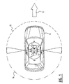
- a vehicle 10 ( figure 1 ) moving in the direction of the arrow 17 is shown with two diametrically placed cameras 11 and 12 located on top of the vehicle.
- the first camera 11 is located in a position relatively forward of the second camera 12 with regard to the moving direction of the vehicle 10.
- the first camera is facing substantially in the moving direction of the vehicle 10.
- the second camera 12 located backwards of the first camera with regard to the moving direction of the vehicle 10 faces in substantially the opposite direction of the first camera 11.
- the first camera 11 has a viewing angle ⁇ .
- the second camera 12 has a viewing angle ⁇ .
- the sum of the viewing angles ⁇ and ⁇ are such that they exceed 360° so that some overlap in the fields of view allows for the two images to be stitched together.
- the viewing angles ⁇ and ⁇ are about 185°, see the respective circle segments 15 and 16. In the figures the angles ⁇ and ⁇ have been exaggerated for viewing purposes.
- the centre of the circle segments is defined by the respective entrance pupils 13 and 14 of the lens systems of the respective cameras 11 and 12.
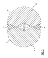
- the fields of view 15 and 16 partially overlap in areas 27 and 28; see also figure 2 .
- This overlap allows for the first image of the first camera 11 and the second image of the second camera 12 to be stitched together.
- the field of view 15 further comprises an area 25 that is only covered by the first image of the first camera 11.
- the field of view 16 also comprises an area 26 that is only covered by the second image of the second camera 12. Area 29 is not covered by any of the two cameras.
- the first image and second image are shot in such a way that the position of the entrance pupil 13 of the first camera 11 coincides as much as possible with the entrance pupil 14 of the second camera 12.
- the two entrance pupils 13 and 14 are made to coincide sufficiently by locating the entrance pupils in substantially the same position, but at different moments in time. This is realised by taking an image with the first camera 11 and then while the vehicle 10 moves further, waiting for the entrance pupil 14 of the second camera 12 to move to the position where the first entrance pupil 13 of the first camera 11 actually was when the first image was taken by the first camera 11.
- the entrance pupil 14 of the second camera 12 has reached the original position of the first entrance pupil 13 of the first camera 11, the second image is taken by the second camera 12. This is denoted by the arrow 21. So in fact the entrance pupil 14 of the second image is virtually moved to the entrance pupil 13 of the first image, resulting in more or less coinciding entrance pupils.
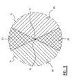
- one of the overlap areas 27 or 28 might disappear resulting in a gap in the omnidirectional image. This happens for example when the vehicle takes a turn between taking the first image and the second image.
- the optical axes will turn with the vehicle causing the second image to be taken with an optical axis being directed differently from the optical axis of the first image.
- This causes the overlap area 27 or 28 at the outer side of the turn to show less overlap and the respective other overlap area 28 or 27 to become larger and subsequently causes one of the overlap areas in the stitching process to become smaller and the other overlap area to become larger.
- the overlap area that has become smaller may become too small for containing information necessary to perform a proper stitch operation.
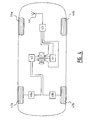
- the diagram of figure 4 shows a first camera 11, facing in a first direction and a second camera 12 facing in a second direction being opposite of the direction of the first camera.
- Odometers 48a and 48b are connected to wheels 47a and 47b.
- the odometers are connected to the non-driven wheels.
- the odometers 48a and 48b are connected to a camera control 42.
- Camera control means 42 control the first and second cameras 11 and 12, sending commands to the cameras when it determines that a first or a second image is to be taken.
- the vehicle is also equipped with a position determining system, in this embodiment with a GPS, comprising an antenna 44 to receive information from navigation satellites and the receiver 43 for detecting and decoding the received signals and calculating the present position of the vehicle.
- the receiver 43 provides a computing means 41 with position information. Based on the position information received from receiver 43 the computing means 41 determines when an omnidirectional image should be acquired.
- the computing means 41 is connected to the camera control 42 and sends a command to start the acquisition of the omnidirectional image. After receiving the command to acquire an image from the computing means 41 camera control 42 sends a command to the first camera 11 to start the acquisition of the first image in the first direction. In the meantime it starts monitoring the distance covered by the vehicle since the first image has been taken by the first camera 11 by monitoring the information supplied by the odometers 48a and 48b.
- the computing means 41 store the first and second images together with the position information received from the position determining system constituted by antenna 44 and receiver 43. Additionally the date and time the images where taken are stored. Next, the computing means 41 starts the stitching process to generate an omnidirectional image. In an alternative embodiment of the present invention the omnidirectional image is not generated on the vehicle itself, but the computing means 41 only stores the first and second image in order to be stitched together at a later stage preferably on a powerful non-mobile computing means external to the vehicle.
Landscapes
- Physics & Mathematics (AREA)
- General Physics & Mathematics (AREA)
- Studio Devices (AREA)
- Image Processing (AREA)
- Image Analysis (AREA)
- Steering-Linkage Mechanisms And Four-Wheel Steering (AREA)
- Control And Safety Of Cranes (AREA)
Claims (26)
- Procédé pour produire une image à partir d'un véhicule en mouvement (10), comprenant les étapes consistant à :- monter une première caméra (11) sur le véhicule (10), la première caméra ayant un champ de vue (15) ;- monter une seconde caméra (12) sur le véhicule (10) et sur une position prédéterminée par rapport à la première caméra (11), la seconde caméra (12) ayant un champ de vue (16) ;- acquérir une première image avec la première caméra (11) ;- acquérir une seconde image avec la seconde caméra (12) après que la première image a été acquise lorsque la position de la seconde caméra est suffisamment proche de ou même coïncide avec la position à partir de laquelle la première image a été prise du fait du mouvement du véhicule, moyennant quoi le champ de vue (16) de la seconde caméra (12) chevauche partiellement le champ de vue (15) de la première caméra (11) lorsque la première image a été prise ;- générer une image en assemblant la première image et la seconde image ensemble.
- Procédé selon la revendication 1, dans lequel la première caméra (11) comprend une première pupille d'entrée (13) et la seconde caméra (12) comprend une seconde pupille d'entrée (14) et dans lequel la première pupille d'entrée (13) et la pupille d'entrée (14) sont situées sur une ligne qui est sensiblement parallèle à la direction prédominante du mouvement du véhicule (10).
- Procédé selon la revendication 1 ou 2, dans lequel la première caméra (11) fait sensiblement face dans la direction prédominante de mouvement du véhicule (10) et la seconde caméra (12) fait sensiblement face dans la direction opposée à celle où la première caméra fait face.
- Procédé selon la revendication 1, 2, ou 3, dans lequel la première caméra (11) est positionnée relativement à l'avant de la seconde caméra (12) en considérant la direction prédominante de mouvement du véhicule (10).
- Procédé selon l'une quelconque des revendications 1 à 4, dans lequel la somme des angles de vue de la première et de la seconde caméra (11, 12) dépasse 360°.
- Procédé selon l'une quelconque des revendications 1 à 5, dans lequel l'angle de vue d'au moins une de la première et de la seconde caméra (11, 12) est d'environ 185°.
- Procédé selon l'une quelconque des revendications 1 à 6, dans lequel la position de la seconde caméra (12) est suffisamment proche de la position à partir de laquelle la première image a été prise si la pupille d'entrée (14) de la seconde caméra (12) est à une distance prédéterminée de la position où la pupille d'entrée (13) de la première caméra (11) se trouvait lorsque la première image a été prise.
- Procédé selon la revendication 7, dans lequel la distance prédéterminée s'élève à 5 centimètres.
- Procédé selon la revendication 7, dans lequel la distance prédéterminée s'élève à 1 centimètre.
- Procédé selon l'une quelconque des revendications 1 à 9, dans lequel la distance parcourue est déterminée au moyen d'au moins un odomètre (48a, 48b).
- Procédé selon l'une quelconque des revendications 1 à 9, dans lequel la distance parcourue est mesurée au moyen d'au moins un système de détermination de position (43).
- Procédé selon la revendication 11, dans lequel le système de détermination de position (43) comprend un système de navigation par satellite.
- Procédé selon la revendication 12, dans lequel le système de navigation par satellite comprend le système mondial de positionnement (GPS).
- Procédé selon l'une quelconque des revendications 1 à 9, dans lequel la distance parcourue est déterminée au moyen d'une combinaison d'un système de détermination de position (43) et d'au moins un odomètre (48a, 48b).
- Procédé selon l'une quelconque des revendications 1 à 14, dans lequel la distance parcourue est mesurée au moyen d'au moins un système de navigation inertielle (INS).
- Procédé selon l'une quelconque des revendications 1 à 15, dans lequel des moyens de détermination d'orientation déterminent l'orientation du véhicule lorsqu'une image est acquise et utilisent l'orientation du véhicule pendant le processus d'assemblage.
- Procédé selon l'une quelconque des revendications 1 à 16, comprenant les étapes consistant à :- monter au moins une caméra additionnelle sur le véhicule (10) sur une position prédéterminée par rapport à la première caméra (11), ayant un champ de vue ;- acquérir une image additionnelle avec la caméra additionnelle lorsque la position de la caméra additionnelle est suffisamment proche de ou même coïncide avec la position à partir de laquelle la première image a été prise, moyennant quoi le champ de vue de la caméra additionnelle chevauche partiellement le champ de vue (15) de la première caméra (11), le champ de vue (16) de la seconde caméra (12), et/ou le champ de vue d'une quelconque autre caméra qui a acquis une image après que la première caméra (11) a acquis la première image lorsque la première image, la seconde image, ou l'autre image a été prise.
- Procédé selon la revendication 17, caractérisé en ce qu'il y a deux caméras additionnelles, chaque caméra couvrant un angle de vue d'un peu plus de 90°.
- Procédé selon la revendication 17 ou 18, incluant plus de deux caméras additionnelles.
- Système pour générer une image à partir d'un véhicule, comprenant :- des premiers moyens d'imagerie devant être montés sur le véhicule (10) ;- des seconds moyens d'imagerie devant être montés sur le véhicule (10) sur une position prédéterminée par rapport aux premiers moyens d'imagerie ;- des moyens de mesure de distance parcourue pour mesurer la distance parcourue par le véhicule (10) ; et- des moyens de commande (42) connectés aux premiers et seconds moyens d'imagerie pour commander l'acquisition d'une première image par les premiers moyens d'imagerie et d'une seconde image par les seconds moyens d'imagerie et connectés aux moyens de mesure de distance parcourue pour initier l'acquisition de la seconde image après le parcours du véhicule (10) de sorte que la position des seconds moyens d'imagerie soit suffisamment proche de la position des premiers moyens d'imagerie pendant l'acquisition de la première image.
- Système selon la revendication 20, dans lequel les moyens de mesure de distance parcourue comprennent au moins un odomètre (48a, 48b).
- Système selon la revendication 21, dans lequel le véhicule (10) comprend au moins une roue non motrice et l'odomètre (48a, 48b) est connecté à la roue non motrice.
- Système selon la revendication 20, dans lequel les moyens de mesure de distance parcourue comprennent un système de détermination de position (43).
- Système selon la revendication 20, dans lequel les moyens de détermination de position (43) comprennent un système de navigation par satellite.
- Système selon la revendication 20, dans lequel les moyens de mesure de distance parcourue comprennent une combinaison d'un système de détermination de position (43) et d'au moins un odomètre (48a, 48b).
- Véhicule (10) avec un système conformément à l'une des revendications 20 à 25 monté dessus.
Priority Applications (12)
| Application Number | Priority Date | Filing Date | Title |
|---|---|---|---|
| PT06019920T PT1903534E (pt) | 2006-09-22 | 2006-09-22 | Método e sistema para produzir uma imagem panorâmica a partir de um veículo |
| EP06019920A EP1903534B1 (fr) | 2006-09-22 | 2006-09-22 | Méthode et système pour produire une image panoramique à partir d'un véhicule. |
| PL06019920T PL1903534T3 (pl) | 2006-09-22 | 2006-09-22 | Sposób i system generowania obrazu panoramicznego z pokładu pojazdu |
| DK06019920T DK1903534T3 (da) | 2006-09-22 | 2006-09-22 | Fremgangsmåde og anlæg til tilvejebringelse af et billede fra et fartöj eller et köretöj |
| ES06019920T ES2317394T3 (es) | 2006-09-22 | 2006-09-22 | Metodo y sistema para producir una imagen panomarica desde un vehiculo. |
| DE602006004215T DE602006004215D1 (de) | 2006-09-22 | 2006-09-22 | Methode und System zum Erzeugen eines Panoramabildes ausgehend von einem Fahrzeug |
| AT06019920T ATE417342T1 (de) | 2006-09-22 | 2006-09-22 | Methode und system zum erzeugen eines panoramabildes ausgehend von einem fahrzeug |
| SI200630162T SI1903534T1 (sl) | 2006-09-22 | 2006-09-22 | Metoda in sistem za izdelavo panoramske slike z vozila med voĺ˝njo |
| CA2603329A CA2603329C (fr) | 2006-09-22 | 2007-09-20 | Methode et systeme pour produire une image a partir d'un vehicule |
| US11/859,538 US7961979B2 (en) | 2006-09-22 | 2007-09-21 | Method and system for producing an image from a vehicle |
| BRPI0704526-3A BRPI0704526A (pt) | 2006-09-22 | 2007-09-21 | método para produção de uma imagem a partir de um veìculo, sistema para geração de uma imagem a partir de um veìculo, e veìculo |
| CY20091100052T CY1109538T1 (el) | 2006-09-22 | 2009-01-15 | Μεθοδος και συστημα για την παραγωγη μιας πανοραμικης εικονας απο ενα οχημα |
Applications Claiming Priority (1)
| Application Number | Priority Date | Filing Date | Title |
|---|---|---|---|
| EP06019920A EP1903534B1 (fr) | 2006-09-22 | 2006-09-22 | Méthode et système pour produire une image panoramique à partir d'un véhicule. |
Publications (2)
| Publication Number | Publication Date |
|---|---|
| EP1903534A1 EP1903534A1 (fr) | 2008-03-26 |
| EP1903534B1 true EP1903534B1 (fr) | 2008-12-10 |
Family
ID=37713812
Family Applications (1)
| Application Number | Title | Priority Date | Filing Date |
|---|---|---|---|
| EP06019920A Active EP1903534B1 (fr) | 2006-09-22 | 2006-09-22 | Méthode et système pour produire une image panoramique à partir d'un véhicule. |
Country Status (12)
| Country | Link |
|---|---|
| US (1) | US7961979B2 (fr) |
| EP (1) | EP1903534B1 (fr) |
| AT (1) | ATE417342T1 (fr) |
| BR (1) | BRPI0704526A (fr) |
| CA (1) | CA2603329C (fr) |
| CY (1) | CY1109538T1 (fr) |
| DE (1) | DE602006004215D1 (fr) |
| DK (1) | DK1903534T3 (fr) |
| ES (1) | ES2317394T3 (fr) |
| PL (1) | PL1903534T3 (fr) |
| PT (1) | PT1903534E (fr) |
| SI (1) | SI1903534T1 (fr) |
Families Citing this family (14)
| Publication number | Priority date | Publication date | Assignee | Title |
|---|---|---|---|---|
| US8850011B2 (en) * | 2005-04-21 | 2014-09-30 | Microsoft Corporation | Obtaining and displaying virtual earth images |
| CA2684516C (fr) | 2007-04-22 | 2018-02-06 | Ilookabout Inc. | Procede d'obtention d'images geographiquement liees utilisant un vehicule |
| TWI401612B (zh) * | 2010-03-23 | 2013-07-11 | Ind Tech Res Inst | 全周鳥瞰影像亮度均化方法及全周鳥瞰影像形成系統 |
| NL2004996C2 (nl) * | 2010-06-29 | 2011-12-30 | Cyclomedia Technology B V | Werkwijze voor het vervaardigen van een digitale foto, waarbij ten minste een deel van de beeldelementen positieinformatie omvatten en een dergelijke digitale foto. |
| DE102012215026A1 (de) * | 2012-08-23 | 2014-05-28 | Bayerische Motoren Werke Aktiengesellschaft | Verfahren und Vorrichtung zum Betreiben eines Fahrzeugs |
| NL2010463C2 (nl) | 2013-03-15 | 2014-09-16 | Cyclomedia Technology B V | Werkwijze voor het genereren van een panoramabeeld. |
| DE102013213872B4 (de) | 2013-07-16 | 2023-10-05 | Bayerische Motoren Werke Aktiengesellschaft | Fahrzeug mit Auslöseeinrichtung |
| DE102013012522A1 (de) | 2013-07-27 | 2015-01-29 | Daimler Ag | Bilderfassungseinrichtung für einen Kraftwagen, Kraftwagen mit einer Bilderfassungseinrichtung und Verfahren zum Betreiben einer Bilderfassungseinrichtung |
| EP3190460A1 (fr) * | 2016-01-05 | 2017-07-12 | Giroptic | Dispositif de capture d'image sur un corps mobile |
| CN109029364A (zh) * | 2018-06-04 | 2018-12-18 | 江西冠翔科技有限公司 | 一种车载式现场勘查系统 |
| CN110246081B (zh) * | 2018-11-07 | 2023-03-17 | 浙江大华技术股份有限公司 | 一种图像拼接方法、装置及可读存储介质 |
| GB2591278A (en) * | 2020-01-24 | 2021-07-28 | Bombardier Transp Gmbh | A monitoring system of a rail vehicle, a method for monitoring and a rail vehicle |
| NL2028357B1 (en) * | 2021-06-01 | 2022-12-13 | Cyclomedia Tech B V | Method for training a neural network |
| NL2028779B1 (en) | 2021-07-19 | 2023-01-25 | Cyclomedia Tech B V | Triggering system |
Family Cites Families (7)
| Publication number | Priority date | Publication date | Assignee | Title |
|---|---|---|---|---|
| WO1997000425A2 (fr) * | 1995-06-16 | 1997-01-03 | Philips Electronics N.V. | Systeme permettant de rattacher des elements a des intersections et des liaisons complexes dans la representation d'un reseau routier pour les vehicules |
| US6331869B1 (en) * | 1998-08-07 | 2001-12-18 | Be Here Corporation | Method and apparatus for electronically distributing motion panoramic images |
| US6563960B1 (en) | 1999-09-28 | 2003-05-13 | Hewlett-Packard Company | Method for merging images |
| US6411742B1 (en) | 2000-05-16 | 2002-06-25 | Adobe Systems Incorporated | Merging images to form a panoramic image |
| JP2002209208A (ja) * | 2001-01-11 | 2002-07-26 | Mixed Reality Systems Laboratory Inc | 画像処理装置及びその方法並びに記憶媒体 |
| US7126630B1 (en) * | 2001-02-09 | 2006-10-24 | Kujin Lee | Method and apparatus for omni-directional image and 3-dimensional data acquisition with data annotation and dynamic range extension method |
| DE10303015A1 (de) * | 2003-01-27 | 2004-08-12 | Daimlerchrysler Ag | System aus laserscanner und katadioptrischer Kamera |
-
2006
- 2006-09-22 EP EP06019920A patent/EP1903534B1/fr active Active
- 2006-09-22 ES ES06019920T patent/ES2317394T3/es active Active
- 2006-09-22 DE DE602006004215T patent/DE602006004215D1/de active Active
- 2006-09-22 SI SI200630162T patent/SI1903534T1/sl unknown
- 2006-09-22 AT AT06019920T patent/ATE417342T1/de active
- 2006-09-22 DK DK06019920T patent/DK1903534T3/da active
- 2006-09-22 PL PL06019920T patent/PL1903534T3/pl unknown
- 2006-09-22 PT PT06019920T patent/PT1903534E/pt unknown
-
2007
- 2007-09-20 CA CA2603329A patent/CA2603329C/fr active Active
- 2007-09-21 BR BRPI0704526-3A patent/BRPI0704526A/pt not_active Application Discontinuation
- 2007-09-21 US US11/859,538 patent/US7961979B2/en active Active
-
2009
- 2009-01-15 CY CY20091100052T patent/CY1109538T1/el unknown
Also Published As
| Publication number | Publication date |
|---|---|
| DE602006004215D1 (de) | 2009-01-22 |
| BRPI0704526A (pt) | 2008-05-13 |
| ATE417342T1 (de) | 2008-12-15 |
| US7961979B2 (en) | 2011-06-14 |
| PT1903534E (pt) | 2009-02-03 |
| CA2603329A1 (fr) | 2008-03-22 |
| CA2603329C (fr) | 2016-01-12 |
| SI1903534T1 (sl) | 2009-04-30 |
| US20080075391A1 (en) | 2008-03-27 |
| CY1109538T1 (el) | 2014-08-13 |
| EP1903534A1 (fr) | 2008-03-26 |
| DK1903534T3 (da) | 2009-04-14 |
| PL1903534T3 (pl) | 2009-05-29 |
| ES2317394T3 (es) | 2009-04-16 |
Similar Documents
| Publication | Publication Date | Title |
|---|---|---|
| CA2603329C (fr) | Methode et systeme pour produire une image a partir d'un vehicule | |
| CN1896684B (zh) | 地理数据收集装置 | |
| US9564047B2 (en) | Traffic monitoring system and traffic monitoring method in which a traffic control center configured a three dimensional traffic image | |
| US6650360B1 (en) | Camera guidance system | |
| US20110050903A1 (en) | Method for determining position and orientation of vehicle trailers | |
| JP4469471B2 (ja) | 移動体用広視野角多方向画像取得装置及び移動体用広視野角多方向画像取得システム | |
| US8174562B2 (en) | Stereo camera having 360 degree field of view | |
| US10613231B2 (en) | Portable GNSS survey system | |
| US20160035096A1 (en) | Scene documentation | |
| JP6764693B2 (ja) | 衛星信号処理方法及び衛星信号処理装置 | |
| US8363928B1 (en) | General orientation positioning system | |
| US20140049654A1 (en) | Information providing system, information providing device, image capture device, and computer program | |
| US20200025943A1 (en) | Methods for geospatial positioning and portable positioning devices thereof | |
| US6879284B2 (en) | Method and apparatus for identifying objects | |
| FR2999303A1 (fr) | Procede de geo localisation precise d'un capteur d'images embarque a bord d'un aeronef | |
| Niu et al. | A continuous positioning algorithm based on RTK and VI-SLAM with smartphones | |
| WO2015168460A1 (fr) | Système de navigation à l'estime basé sur un mesurage local du mouvement | |
| KR20030070553A (ko) | 촬영영상 처리방법 | |
| CN113296133A (zh) | 一种基于双目视觉测量与高精度定位融合技术实现位置标定的装置及方法 | |
| CA2569209A1 (fr) | Systeme et methode de navigation inertielle augmentee d'images (image-augmented inertial navigation system, iains) | |
| US9019348B2 (en) | Display device, image pickup device, and video display system | |
| US20100085467A1 (en) | Image pickup device capable of providing gps coordinates of subject to be shot and method for detecting gps coordinates thereof | |
| JP5920807B2 (ja) | 光軸方向特定方法、光軸方向特定装置、及び光軸方向特定プログラム | |
| CN115856959B (zh) | 手机相机辅助的多卫星导航系统选星方法及系统 | |
| KR101220266B1 (ko) | 수치지도 이미지 제작을 위한 항공영상 이미지 기반 정밀 영상도화 시스템 |
Legal Events
| Date | Code | Title | Description |
|---|---|---|---|
| PUAI | Public reference made under article 153(3) epc to a published international application that has entered the european phase |
Free format text: ORIGINAL CODE: 0009012 |
|
| 17P | Request for examination filed |
Effective date: 20070713 |
|
| AK | Designated contracting states |
Kind code of ref document: A1 Designated state(s): AT BE BG CH CY CZ DE DK EE ES FI FR GB GR HU IE IS IT LI LT LU LV MC NL PL PT RO SE SI SK TR |
|
| AX | Request for extension of the european patent |
Extension state: AL BA HR MK YU |
|
| GRAP | Despatch of communication of intention to grant a patent |
Free format text: ORIGINAL CODE: EPIDOSNIGR1 |
|
| GRAS | Grant fee paid |
Free format text: ORIGINAL CODE: EPIDOSNIGR3 |
|
| GRAA | (expected) grant |
Free format text: ORIGINAL CODE: 0009210 |
|
| AKX | Designation fees paid |
Designated state(s): AT BE BG CH CY CZ DE DK EE ES FI FR GB GR HU IE IS IT LI LT LU LV MC NL PL PT RO SE SI SK TR |
|
| AK | Designated contracting states |
Kind code of ref document: B1 Designated state(s): AT BE BG CH CY CZ DE DK EE ES FI FR GB GR HU IE IS IT LI LT LU LV MC NL PL PT RO SE SI SK TR |
|
| REG | Reference to a national code |
Ref country code: GB Ref legal event code: FG4D |
|
| REG | Reference to a national code |
Ref country code: CH Ref legal event code: EP Ref country code: CH Ref legal event code: NV Representative=s name: ARNOLD & SIEDSMA AG |
|
| REG | Reference to a national code |
Ref country code: GR Ref legal event code: EP Ref document number: 20080403481 Country of ref document: GR |
|
| REG | Reference to a national code |
Ref country code: IE Ref legal event code: FG4D |
|
| REF | Corresponds to: |
Ref document number: 602006004215 Country of ref document: DE Date of ref document: 20090122 Kind code of ref document: P |
|
| REG | Reference to a national code |
Ref country code: PT Ref legal event code: SC4A Free format text: AVAILABILITY OF NATIONAL TRANSLATION Effective date: 20090122 |
|
| REG | Reference to a national code |
Ref country code: SE Ref legal event code: TRGR |
|
| REG | Reference to a national code |
Ref country code: RO Ref legal event code: EPE |
|
| REG | Reference to a national code |
Ref country code: DK Ref legal event code: T3 |
|
| REG | Reference to a national code |
Ref country code: ES Ref legal event code: FG2A Ref document number: 2317394 Country of ref document: ES Kind code of ref document: T3 |
|
| REG | Reference to a national code |
Ref country code: PL Ref legal event code: T3 |
|
| REG | Reference to a national code |
Ref country code: HU Ref legal event code: AG4A Ref document number: E005292 Country of ref document: HU |
|
| PLBE | No opposition filed within time limit |
Free format text: ORIGINAL CODE: 0009261 |
|
| STAA | Information on the status of an ep patent application or granted ep patent |
Free format text: STATUS: NO OPPOSITION FILED WITHIN TIME LIMIT |
|
| 26N | No opposition filed |
Effective date: 20090911 |
|
| REG | Reference to a national code |
Ref country code: FR Ref legal event code: PLFP Year of fee payment: 11 |
|
| REG | Reference to a national code |
Ref country code: FR Ref legal event code: PLFP Year of fee payment: 12 |
|
| REG | Reference to a national code |
Ref country code: FR Ref legal event code: PLFP Year of fee payment: 13 |
|
| REG | Reference to a national code |
Ref country code: NL Ref legal event code: RF Free format text: RIGHT OF PLEDGE, REMOVED Effective date: 20181109 |
|
| REG | Reference to a national code |
Ref country code: NL Ref legal event code: RC Free format text: DETAILS LICENCE OR PLEDGE: RIGHT OF PLEDGE, ESTABLISHED Name of requester: COOEPERATIEVE RABOBANK U.A Effective date: 20190215 |
|
| P01 | Opt-out of the competence of the unified patent court (upc) registered |
Effective date: 20230507 |
|
| REG | Reference to a national code |
Ref country code: NL Ref legal event code: RF Free format text: RIGHT OF PLEDGE, REMOVED Effective date: 20231201 |
|
| REG | Reference to a national code |
Ref country code: CH Ref legal event code: U11 Free format text: ST27 STATUS EVENT CODE: U-0-0-U10-U11 (AS PROVIDED BY THE NATIONAL OFFICE) Effective date: 20251001 |
|
| PGFP | Annual fee paid to national office [announced via postgrant information from national office to epo] |
Ref country code: PT Payment date: 20250904 Year of fee payment: 20 Ref country code: FI Payment date: 20250925 Year of fee payment: 20 |
|
| PGFP | Annual fee paid to national office [announced via postgrant information from national office to epo] |
Ref country code: LT Payment date: 20250903 Year of fee payment: 20 Ref country code: DK Payment date: 20250925 Year of fee payment: 20 Ref country code: DE Payment date: 20250929 Year of fee payment: 20 |
|
| PGFP | Annual fee paid to national office [announced via postgrant information from national office to epo] |
Ref country code: MC Payment date: 20250905 Year of fee payment: 20 Ref country code: GR Payment date: 20250926 Year of fee payment: 20 |
|
| PGFP | Annual fee paid to national office [announced via postgrant information from national office to epo] |
Ref country code: PL Payment date: 20250909 Year of fee payment: 20 Ref country code: TR Payment date: 20250908 Year of fee payment: 20 Ref country code: NL Payment date: 20250926 Year of fee payment: 20 Ref country code: LU Payment date: 20250929 Year of fee payment: 20 Ref country code: IT Payment date: 20250919 Year of fee payment: 20 |
|
| PGFP | Annual fee paid to national office [announced via postgrant information from national office to epo] |
Ref country code: BE Payment date: 20250929 Year of fee payment: 20 Ref country code: HU Payment date: 20250910 Year of fee payment: 20 Ref country code: BG Payment date: 20250917 Year of fee payment: 20 Ref country code: GB Payment date: 20250929 Year of fee payment: 20 |
|
| PGFP | Annual fee paid to national office [announced via postgrant information from national office to epo] |
Ref country code: AT Payment date: 20250929 Year of fee payment: 20 Ref country code: FR Payment date: 20250925 Year of fee payment: 20 |
|
| PGFP | Annual fee paid to national office [announced via postgrant information from national office to epo] |
Ref country code: SE Payment date: 20250927 Year of fee payment: 20 |
|
| PGFP | Annual fee paid to national office [announced via postgrant information from national office to epo] |
Ref country code: EE Payment date: 20250909 Year of fee payment: 20 Ref country code: CZ Payment date: 20250908 Year of fee payment: 20 Ref country code: IE Payment date: 20250929 Year of fee payment: 20 |
|
| PGFP | Annual fee paid to national office [announced via postgrant information from national office to epo] |
Ref country code: RO Payment date: 20250909 Year of fee payment: 20 |
|
| PGFP | Annual fee paid to national office [announced via postgrant information from national office to epo] |
Ref country code: SK Payment date: 20250903 Year of fee payment: 20 |
|
| PGFP | Annual fee paid to national office [announced via postgrant information from national office to epo] |
Ref country code: IS Payment date: 20250918 Year of fee payment: 20 |
|
| PGFP | Annual fee paid to national office [announced via postgrant information from national office to epo] |
Ref country code: LV Payment date: 20250903 Year of fee payment: 20 |
|
| PGFP | Annual fee paid to national office [announced via postgrant information from national office to epo] |
Ref country code: SI Payment date: 20250901 Year of fee payment: 20 |
|
| PGFP | Annual fee paid to national office [announced via postgrant information from national office to epo] |
Ref country code: CH Payment date: 20251001 Year of fee payment: 20 |
|
| PGFP | Annual fee paid to national office [announced via postgrant information from national office to epo] |
Ref country code: CY Payment date: 20250909 Year of fee payment: 20 |
|
| PGFP | Annual fee paid to national office [announced via postgrant information from national office to epo] |
Ref country code: ES Payment date: 20251001 Year of fee payment: 20 |