EP1903638A2 - Connecteur électrique - Google Patents
Connecteur électrique Download PDFInfo
- Publication number
- EP1903638A2 EP1903638A2 EP07075792A EP07075792A EP1903638A2 EP 1903638 A2 EP1903638 A2 EP 1903638A2 EP 07075792 A EP07075792 A EP 07075792A EP 07075792 A EP07075792 A EP 07075792A EP 1903638 A2 EP1903638 A2 EP 1903638A2
- Authority
- EP
- European Patent Office
- Prior art keywords
- terminal
- lock
- rigid
- electrical connector
- connector body
- Prior art date
- Legal status (The legal status is an assumption and is not a legal conclusion. Google has not performed a legal analysis and makes no representation as to the accuracy of the status listed.)
- Granted
Links
- 230000013011 mating Effects 0.000 claims description 8
- 230000014759 maintenance of location Effects 0.000 claims description 5
- 238000003780 insertion Methods 0.000 claims description 3
- 230000037431 insertion Effects 0.000 claims description 3
- 230000006978 adaptation Effects 0.000 description 2
- 239000004020 conductor Substances 0.000 description 2
- 230000000994 depressogenic effect Effects 0.000 description 2
- 230000009977 dual effect Effects 0.000 description 2
- 238000012986 modification Methods 0.000 description 2
- 230000004048 modification Effects 0.000 description 2
- 230000000881 depressing effect Effects 0.000 description 1
- 230000002708 enhancing effect Effects 0.000 description 1
- 239000000126 substance Substances 0.000 description 1
Images

Classifications
-
- H—ELECTRICITY
- H01—ELECTRIC ELEMENTS
- H01R—ELECTRICALLY-CONDUCTIVE CONNECTIONS; STRUCTURAL ASSOCIATIONS OF A PLURALITY OF MUTUALLY-INSULATED ELECTRICAL CONNECTING ELEMENTS; COUPLING DEVICES; CURRENT COLLECTORS
- H01R13/00—Details of coupling devices of the kinds covered by groups H01R12/70 or H01R24/00 - H01R33/00
- H01R13/62—Means for facilitating engagement or disengagement of coupling parts or for holding them in engagement
- H01R13/639—Additional means for holding or locking coupling parts together, after engagement, e.g. separate keylock, retainer strap
-
- H—ELECTRICITY
- H01—ELECTRIC ELEMENTS
- H01R—ELECTRICALLY-CONDUCTIVE CONNECTIONS; STRUCTURAL ASSOCIATIONS OF A PLURALITY OF MUTUALLY-INSULATED ELECTRICAL CONNECTING ELEMENTS; COUPLING DEVICES; CURRENT COLLECTORS
- H01R13/00—Details of coupling devices of the kinds covered by groups H01R12/70 or H01R24/00 - H01R33/00
- H01R13/40—Securing contact members in or to a base or case; Insulating of contact members
- H01R13/42—Securing in a demountable manner
- H01R13/422—Securing in resilient one-piece base or case, e.g. by friction; One-piece base or case formed with resilient locking means
- H01R13/4223—Securing in resilient one-piece base or case, e.g. by friction; One-piece base or case formed with resilient locking means comprising integral flexible contact retaining fingers
Definitions
- This invention relates generally to an electrical connector and more particularly to an electrical connector in which the connector body has a flexible beam for enhancing terminal retention.
- U.S. Patent No. 5,980,318 granted to John Morello et al. November 9, 1999 discloses an electrical connector comprising a connector body that has a plurality of terminal receiving cavities. Each terminal receiving cavity is defined in part by a rigid floor and opposed upright walls. A rigid lock nib extends upwardly from the rigid floor into the terminal receiving cavity. A flexible beam opposes the rigid floor and engages a terminal in the cavity to hold the terminal against the rigid lock nib to retain the terminal in the terminal receiving cavity.
- the connector body is constructed and arranged for receiving a terminal in each terminal receiving cavity. This electrical connector is well suited for its intended purpose of housing and retaining terminals. However, terminal retention may be enhanced.
- This invention provides an electrical connector comprising a connector body that has a terminal receiving cavity.
- the terminal receiving cavity is defined in part by a rigid wall and opposed upright walls.
- a rigid lock nib extends inwardly from the rigid wall into the terminal receiving cavity to retain a terminal in the receiving cavity.
- the connector body has a dual function flexible beam opposite the rigid wall of the terminal cavity. The flexible beam engages the terminal in the cavity to hold the terminal against the rigid lock nib to retain the terminal in the terminal receiving cavity.
- the flexible beam has a second rigid lock nib to enhance terminal retention.
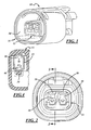
- Figure 1 is a perspective view of an electrical connector illustrating an embodiment of the invention
- Figure 2 is a front view of the electrical connector of figure 1;
- Figure 3 is a longitudinal section of the electrical connector of figure 1 taken substantially along the line 3-3 of figure 2 looking in the direction of the arrows;
- Figure 4 is a transverse section of the electrical connector of figure 1 taken substantially along the line 4-4 of figure 3 looking in the direction of the arrows.
- electrical connector 10 comprises a connector body 12, a plurality of terminals 14 attached to insulated conductor wires 16.
- Connector body 12 has two terminal cavities 20 that extend through the connector body 12 from openings at an insertion end 22 to openings into an integral socket 24 at a mating end 26 of the connector body.
- Connector body 12 has rigid lock nibs 28 that project inward into the terminal cavities 20 from a rigid wall 18 for retaining the terminals 14 in the connector body 12.
- Flexible beams 30 opposite the rigid lock nibs 28 push the terminals 14 against the rigid wall 18 for retaining engagement with the rigid lock nibs 28 as best shown in figure 3.
- the flexible beams 30 comprise second rigid lock nibs 32 and thus perform a dual function that enhances retention of terminals 14 in the terminal cavities 20 of connector body 12.
- rigid lock nib 28 comprises a first ramp 34 that slopes inwardly and forwardly toward the mating end 26 of connector body 12.
- Ramp 34 leads to a first lock shoulder 36.
- the first lock shoulder 36 is preferably but not necessarily set at a slight back angle.
- the connector body 12 may include an access slot 38 for each terminal cavity 20 that extends inwardly from an opening at the mating end 26 of connector body 12 to the lock shoulder 36. The purpose of the access slot 38 is explained below.
- the flexible beam 30 is attached at each end to longitudinally spaced rigid spaced wall portions 40 and 42 of connector body 12 that are opposite the rigid wall 18.
- the flexible beam 30 has a second rigid lock nib 32 comprising a second ramp 44 that also slopes inwardly and forwardly toward the mating end 26 of connector body 12.
- the second ramp 44 of the flexible beam 30 may have a lower slope so that terminal engages the second ramp 44 of the flexible beam 30 prior to engaging the ramp 34 of the rigid lock nib 28. This arrangement reduces the force required to insert and lock the terminal 14 in the terminal cavities 20 because the terminals do not engage the ramps 34 and 44 simultaneously.
- Ramp 44 leads to a second lock shoulder 46.
- the second lock shoulder 46 is also preferably, but not necessarily, set at a slight back angle.
- the flexible beam 30 includes a pressure pad 48 forwardly of the second lock shoulder 46.
- the forward contact portion 50 of terminal 14 has laterally spaced lock surfaces 56 and 58.
- the forward contact portion 50 also preferably has ramps 60 and 62 that slant outwardly and rearwardly and lead to the respective lock surfaces 56 and 58.
- the forward contact portion 50 also preferably includes flats 64 and 66 located between the ramps 60 and 62 and the respective lock surfaces 56 and 58.
- Terminals 14 are inserted into the respective terminal cavities 20 through openings at the insertion end 22 of the connector body 12.
- the flexible beam 20 is depressed.
- the flexible beam 20 is then continuously depressed further and further as the contact portion 50 rides along ramp 44, eventually engaging ramp 34 and then also riding along ramp 34.
- terminal lock surfaces 56 and 58 reach lock shoulders 36 and 46, flexible beam 20 springs up whereupon pressure pad 48 engages flat 66 so that the flexible beam 30 pushes terminal 14 against rigid wall 18 and the two rigid lock nibs 28 and 32 engage behind the respective lock surfaces 56 and 58 of terminal 14.
- Terminals 14 are preferably but not necessarily symmetrical about a horizontal plane so that the terminals 14 are insertable into the respective terminal cavities 20 either right side up as best shown in figure 3 or upside down.
- Each terminal 14 can be removed from its terminal cavity 20 by inserting a tool into access slot 38 and depressing the terminal 14 until the lock surfaces 56 and 58 are released by the lock shoulders 36 and 46 rigid lock nibs 28 and 32.
- electrical connector 10 is illustrated with two terminal cavities 20, the electrical connector may have one or any multiple number of terminal cavities.
Landscapes
- Connector Housings Or Holding Contact Members (AREA)
- Coupling Device And Connection With Printed Circuit (AREA)
- Multi-Conductor Connections (AREA)
Applications Claiming Priority (1)
| Application Number | Priority Date | Filing Date | Title |
|---|---|---|---|
| US11/523,414 US7396255B2 (en) | 2006-09-19 | 2006-09-19 | Electrical connector |
Publications (3)
| Publication Number | Publication Date |
|---|---|
| EP1903638A2 true EP1903638A2 (fr) | 2008-03-26 |
| EP1903638A3 EP1903638A3 (fr) | 2008-07-09 |
| EP1903638B1 EP1903638B1 (fr) | 2015-11-11 |
Family
ID=38829223
Family Applications (1)
| Application Number | Title | Priority Date | Filing Date |
|---|---|---|---|
| EP07075792.7A Not-in-force EP1903638B1 (fr) | 2006-09-19 | 2007-09-11 | Connecteur électrique |
Country Status (5)
| Country | Link |
|---|---|
| US (1) | US7396255B2 (fr) |
| EP (1) | EP1903638B1 (fr) |
| JP (1) | JP4827814B2 (fr) |
| KR (1) | KR100943136B1 (fr) |
| CN (1) | CN101150231B (fr) |
Cited By (1)
| Publication number | Priority date | Publication date | Assignee | Title |
|---|---|---|---|---|
| WO2012017064A1 (fr) * | 2010-08-05 | 2012-02-09 | Phoenix Contact Gmbh & Co. Kg | Corps de base pour un connecteur enfichable et connecteur enfichable |
Families Citing this family (19)
| Publication number | Priority date | Publication date | Assignee | Title |
|---|---|---|---|---|
| KR20090105164A (ko) * | 2008-04-01 | 2009-10-07 | 한국단자공업 주식회사 | 커넥터 |
| US7780485B2 (en) * | 2008-08-12 | 2010-08-24 | Delphi Technologies, Inc. | Electrical connector |
| US7658645B1 (en) | 2008-08-12 | 2010-02-09 | Delphi Technologies, Inc. | Electrical connector |
| US7635286B1 (en) | 2008-10-14 | 2009-12-22 | Delphi Technologies, Inc. | Electrical connector |
| ATE542270T1 (de) * | 2009-03-11 | 2012-02-15 | Delphi Tech Inc | Steckverbindergehäuse |
| JP5301351B2 (ja) * | 2009-05-20 | 2013-09-25 | モレックス インコーポレイテド | 電線対基板コネクタ及び電線コネクタ |
| JP5682061B2 (ja) * | 2010-12-21 | 2015-03-11 | 矢崎総業株式会社 | コネクタ |
| JP6141612B2 (ja) * | 2012-09-21 | 2017-06-07 | 矢崎総業株式会社 | コネクタ |
| JP6125891B2 (ja) * | 2013-05-07 | 2017-05-10 | 矢崎総業株式会社 | 端子金具の保持構造 |
| US9071016B2 (en) | 2013-10-03 | 2015-06-30 | Delphi Technologies, Inc. | Electrical connector with a sliding flexible cantilever beam terminal retainer |
| US9407026B2 (en) | 2014-07-14 | 2016-08-02 | Delphi Technologies, Inc. | Electrical connector with a terminal position assurance device |
| US9472885B2 (en) * | 2014-12-08 | 2016-10-18 | Delphi Technologies, Inc. | Electrical connector assembly with low terminal insertion force |
| CN104934752B (zh) * | 2015-06-30 | 2017-05-10 | 威灵(芜湖)电机制造有限公司 | 电连接器及电机 |
| US9735491B2 (en) * | 2015-07-15 | 2017-08-15 | Dynomax Inc. | Easily removable contacts for micro connectors |
| US10333241B2 (en) * | 2016-07-12 | 2019-06-25 | Dynomax Inc. | Easily removable contacts for micro connectors |
| US9899758B1 (en) * | 2017-01-25 | 2018-02-20 | Delphi Technologies, Inc. | Electrical connector system with enhanced terminal retaining beam |
| US9793639B1 (en) * | 2017-02-02 | 2017-10-17 | Delphi Technologies, Inc. | Electrical connector system with multiple flexible terminal retaining beams |
| US9917381B1 (en) | 2017-02-14 | 2018-03-13 | Delphi Technologies, Inc. | Electrical connector with a terminal position assurance device having rigid and flexible locking features |
| US12237608B2 (en) | 2022-06-21 | 2025-02-25 | Aptiv Technologies AG | Electrical connector assembly with flexible and rigid terminal locking features |
Citations (1)
| Publication number | Priority date | Publication date | Assignee | Title |
|---|---|---|---|---|
| US5980318A (en) | 1997-06-25 | 1999-11-09 | General Motors Corporation | Connector with a flexible beam for holding a terminal down and in position |
Family Cites Families (16)
| Publication number | Priority date | Publication date | Assignee | Title |
|---|---|---|---|---|
| JPH0611945B2 (ja) * | 1986-10-24 | 1994-02-16 | 東リ株式会社 | 導電性化粧シ−ト |
| FR2615664B1 (fr) * | 1987-05-22 | 1989-07-13 | Labinal | Connecteur electrique |
| EP0361771A3 (fr) * | 1988-09-26 | 1990-10-31 | Interlock Corporation | Assemblage de bornes avec des rétentions de contacts à clapets |
| JPH0355674A (ja) * | 1989-07-24 | 1991-03-11 | Nippon Telegr & Teleph Corp <Ntt> | 情景解釈処理方法 |
| US4998896A (en) * | 1989-09-25 | 1991-03-12 | Amp Incorporated | Sealed stamped and formed pin |
| JPH0472565A (ja) * | 1990-07-13 | 1992-03-06 | Canon Inc | 検出試薬 |
| JPH0713399B2 (ja) * | 1990-08-25 | 1995-02-15 | 典明 正木 | 構築物用吊り足場の鋼管固定部材 |
| US5520553A (en) * | 1994-12-08 | 1996-05-28 | Molex Incorporated | Connector with a front end mounted terminal position assurance system |
| US5879174A (en) | 1997-08-06 | 1999-03-09 | General Motors Corporation | Dimensional variance spring |
| JPH1174016A (ja) * | 1997-08-28 | 1999-03-16 | Union Mach Kk | コネクタ |
| JP2003257532A (ja) * | 2002-03-01 | 2003-09-12 | Sumitomo Wiring Syst Ltd | コネクタ |
| JP3415141B1 (ja) * | 2002-07-23 | 2003-06-09 | 住友電装株式会社 | コネクタ |
| JP4705354B2 (ja) * | 2003-09-18 | 2011-06-22 | 日本圧着端子製造株式会社 | コネクタ |
| JP2005158418A (ja) * | 2003-11-25 | 2005-06-16 | Sumitomo Wiring Syst Ltd | コネクタ |
| US20060292928A1 (en) * | 2005-06-23 | 2006-12-28 | Morello John R | Electrical connector |
| US7048584B1 (en) * | 2005-06-23 | 2006-05-23 | Delphi Technologies, Inc. | Electrical connector |
-
2006
- 2006-09-19 US US11/523,414 patent/US7396255B2/en active Active
-
2007
- 2007-09-11 EP EP07075792.7A patent/EP1903638B1/fr not_active Not-in-force
- 2007-09-18 KR KR1020070094472A patent/KR100943136B1/ko not_active Expired - Fee Related
- 2007-09-18 CN CN2007101528734A patent/CN101150231B/zh not_active Expired - Fee Related
- 2007-09-19 JP JP2007241700A patent/JP4827814B2/ja not_active Expired - Fee Related
Patent Citations (1)
| Publication number | Priority date | Publication date | Assignee | Title |
|---|---|---|---|---|
| US5980318A (en) | 1997-06-25 | 1999-11-09 | General Motors Corporation | Connector with a flexible beam for holding a terminal down and in position |
Cited By (1)
| Publication number | Priority date | Publication date | Assignee | Title |
|---|---|---|---|---|
| WO2012017064A1 (fr) * | 2010-08-05 | 2012-02-09 | Phoenix Contact Gmbh & Co. Kg | Corps de base pour un connecteur enfichable et connecteur enfichable |
Also Published As
| Publication number | Publication date |
|---|---|
| KR20080026043A (ko) | 2008-03-24 |
| US20080070440A1 (en) | 2008-03-20 |
| CN101150231B (zh) | 2012-11-14 |
| US7396255B2 (en) | 2008-07-08 |
| KR100943136B1 (ko) | 2010-02-18 |
| CN101150231A (zh) | 2008-03-26 |
| EP1903638B1 (fr) | 2015-11-11 |
| EP1903638A3 (fr) | 2008-07-09 |
| JP2008078138A (ja) | 2008-04-03 |
| JP4827814B2 (ja) | 2011-11-30 |
Similar Documents
| Publication | Publication Date | Title |
|---|---|---|
| EP1903638B1 (fr) | Connecteur électrique | |
| CN105281125B (zh) | 带有端子位置保证装置的电连接器 | |
| US7497721B2 (en) | Tool extractable contacts for electrical connectors | |
| US9071016B2 (en) | Electrical connector with a sliding flexible cantilever beam terminal retainer | |
| JP4549373B2 (ja) | 電気的接続装置 | |
| US5980318A (en) | Connector with a flexible beam for holding a terminal down and in position | |
| JP4555223B2 (ja) | 接続端子 | |
| US8747156B2 (en) | Terminal fitting | |
| JP2018139209A (ja) | 端子位置保証装置を有する電気コネクタ | |
| US20090269975A1 (en) | Shorting terminal, connector and shorting method | |
| EP1215765A2 (fr) | Borne femelle à sertir | |
| US7114998B2 (en) | Divided connector and connector assembly | |
| EP0954060A3 (fr) | Connecteur électrique d'éléments de verrouillage secondaires déviables | |
| US20090142958A1 (en) | Connector | |
| US6482035B2 (en) | Press-connecting connector | |
| EP1335456A3 (fr) | Disposition de connecteur électrique | |
| EP1351339A1 (fr) | Un connecteur miniaturisé | |
| US7344419B2 (en) | Connector | |
| JP3039313B2 (ja) | ロック機構 | |
| JP7202531B2 (ja) | コネクタ | |
| CN101208838B (zh) | 电连接器 | |
| US7347748B2 (en) | Terminal fitting and connector provided therewith | |
| JP2014107235A (ja) | コネクタ |
Legal Events
| Date | Code | Title | Description |
|---|---|---|---|
| PUAI | Public reference made under article 153(3) epc to a published international application that has entered the european phase |
Free format text: ORIGINAL CODE: 0009012 |
|
| AK | Designated contracting states |
Kind code of ref document: A2 Designated state(s): AT BE BG CH CY CZ DE DK EE ES FI FR GB GR HU IE IS IT LI LT LU LV MC MT NL PL PT RO SE SI SK TR |
|
| AX | Request for extension of the european patent |
Extension state: AL BA HR MK YU |
|
| RIN1 | Information on inventor provided before grant (corrected) |
Inventor name: STRANG, WILLIAM G. Inventor name: MORELLO, JOHN R. Inventor name: RHINEHART JR., GERALD A. Inventor name: MORELLO, THOMAS G. |
|
| PUAL | Search report despatched |
Free format text: ORIGINAL CODE: 0009013 |
|
| AK | Designated contracting states |
Kind code of ref document: A3 Designated state(s): AT BE BG CH CY CZ DE DK EE ES FI FR GB GR HU IE IS IT LI LT LU LV MC MT NL PL PT RO SE SI SK TR |
|
| AX | Request for extension of the european patent |
Extension state: AL BA HR MK RS |
|
| 17P | Request for examination filed |
Effective date: 20090109 |
|
| 17Q | First examination report despatched |
Effective date: 20090211 |
|
| AKX | Designation fees paid |
Designated state(s): AT BE BG CH CY CZ DE DK EE ES FI FR GB GR HU IE IS IT LI LT LU LV MC MT NL PL PT RO SE SI SK TR |
|
| GRAP | Despatch of communication of intention to grant a patent |
Free format text: ORIGINAL CODE: EPIDOSNIGR1 |
|
| INTG | Intention to grant announced |
Effective date: 20150702 |
|
| GRAS | Grant fee paid |
Free format text: ORIGINAL CODE: EPIDOSNIGR3 |
|
| GRAA | (expected) grant |
Free format text: ORIGINAL CODE: 0009210 |
|
| AK | Designated contracting states |
Kind code of ref document: B1 Designated state(s): AT BE BG CH CY CZ DE DK EE ES FI FR GB GR HU IE IS IT LI LT LU LV MC MT NL PL PT RO SE SI SK TR |
|
| REG | Reference to a national code |
Ref country code: GB Ref legal event code: FG4D |
|
| REG | Reference to a national code |
Ref country code: CH Ref legal event code: EP |
|
| REG | Reference to a national code |
Ref country code: IE Ref legal event code: FG4D |
|
| REG | Reference to a national code |
Ref country code: AT Ref legal event code: REF Ref document number: 760867 Country of ref document: AT Kind code of ref document: T Effective date: 20151215 |
|
| REG | Reference to a national code |
Ref country code: DE Ref legal event code: R096 Ref document number: 602007043833 Country of ref document: DE |
|
| REG | Reference to a national code |
Ref country code: LT Ref legal event code: MG4D |
|
| REG | Reference to a national code |
Ref country code: NL Ref legal event code: MP Effective date: 20160211 |
|
| REG | Reference to a national code |
Ref country code: AT Ref legal event code: MK05 Ref document number: 760867 Country of ref document: AT Kind code of ref document: T Effective date: 20151111 |
|
| PG25 | Lapsed in a contracting state [announced via postgrant information from national office to epo] |
Ref country code: LT Free format text: LAPSE BECAUSE OF FAILURE TO SUBMIT A TRANSLATION OF THE DESCRIPTION OR TO PAY THE FEE WITHIN THE PRESCRIBED TIME-LIMIT Effective date: 20151111 Ref country code: ES Free format text: LAPSE BECAUSE OF FAILURE TO SUBMIT A TRANSLATION OF THE DESCRIPTION OR TO PAY THE FEE WITHIN THE PRESCRIBED TIME-LIMIT Effective date: 20151111 Ref country code: IS Free format text: LAPSE BECAUSE OF FAILURE TO SUBMIT A TRANSLATION OF THE DESCRIPTION OR TO PAY THE FEE WITHIN THE PRESCRIBED TIME-LIMIT Effective date: 20160311 Ref country code: NL Free format text: LAPSE BECAUSE OF FAILURE TO SUBMIT A TRANSLATION OF THE DESCRIPTION OR TO PAY THE FEE WITHIN THE PRESCRIBED TIME-LIMIT Effective date: 20151111 |
|
| PG25 | Lapsed in a contracting state [announced via postgrant information from national office to epo] |
Ref country code: PT Free format text: LAPSE BECAUSE OF FAILURE TO SUBMIT A TRANSLATION OF THE DESCRIPTION OR TO PAY THE FEE WITHIN THE PRESCRIBED TIME-LIMIT Effective date: 20160311 Ref country code: PL Free format text: LAPSE BECAUSE OF FAILURE TO SUBMIT A TRANSLATION OF THE DESCRIPTION OR TO PAY THE FEE WITHIN THE PRESCRIBED TIME-LIMIT Effective date: 20151111 Ref country code: LV Free format text: LAPSE BECAUSE OF FAILURE TO SUBMIT A TRANSLATION OF THE DESCRIPTION OR TO PAY THE FEE WITHIN THE PRESCRIBED TIME-LIMIT Effective date: 20151111 Ref country code: FI Free format text: LAPSE BECAUSE OF FAILURE TO SUBMIT A TRANSLATION OF THE DESCRIPTION OR TO PAY THE FEE WITHIN THE PRESCRIBED TIME-LIMIT Effective date: 20151111 Ref country code: SE Free format text: LAPSE BECAUSE OF FAILURE TO SUBMIT A TRANSLATION OF THE DESCRIPTION OR TO PAY THE FEE WITHIN THE PRESCRIBED TIME-LIMIT Effective date: 20151111 Ref country code: GR Free format text: LAPSE BECAUSE OF FAILURE TO SUBMIT A TRANSLATION OF THE DESCRIPTION OR TO PAY THE FEE WITHIN THE PRESCRIBED TIME-LIMIT Effective date: 20160212 Ref country code: AT Free format text: LAPSE BECAUSE OF FAILURE TO SUBMIT A TRANSLATION OF THE DESCRIPTION OR TO PAY THE FEE WITHIN THE PRESCRIBED TIME-LIMIT Effective date: 20151111 |
|
| PG25 | Lapsed in a contracting state [announced via postgrant information from national office to epo] |
Ref country code: CZ Free format text: LAPSE BECAUSE OF FAILURE TO SUBMIT A TRANSLATION OF THE DESCRIPTION OR TO PAY THE FEE WITHIN THE PRESCRIBED TIME-LIMIT Effective date: 20151111 |
|
| REG | Reference to a national code |
Ref country code: DE Ref legal event code: R097 Ref document number: 602007043833 Country of ref document: DE |
|
| PG25 | Lapsed in a contracting state [announced via postgrant information from national office to epo] |
Ref country code: SK Free format text: LAPSE BECAUSE OF FAILURE TO SUBMIT A TRANSLATION OF THE DESCRIPTION OR TO PAY THE FEE WITHIN THE PRESCRIBED TIME-LIMIT Effective date: 20151111 Ref country code: DK Free format text: LAPSE BECAUSE OF FAILURE TO SUBMIT A TRANSLATION OF THE DESCRIPTION OR TO PAY THE FEE WITHIN THE PRESCRIBED TIME-LIMIT Effective date: 20151111 Ref country code: RO Free format text: LAPSE BECAUSE OF FAILURE TO SUBMIT A TRANSLATION OF THE DESCRIPTION OR TO PAY THE FEE WITHIN THE PRESCRIBED TIME-LIMIT Effective date: 20151111 Ref country code: EE Free format text: LAPSE BECAUSE OF FAILURE TO SUBMIT A TRANSLATION OF THE DESCRIPTION OR TO PAY THE FEE WITHIN THE PRESCRIBED TIME-LIMIT Effective date: 20151111 |
|
| PLBE | No opposition filed within time limit |
Free format text: ORIGINAL CODE: 0009261 |
|
| STAA | Information on the status of an ep patent application or granted ep patent |
Free format text: STATUS: NO OPPOSITION FILED WITHIN TIME LIMIT |
|
| REG | Reference to a national code |
Ref country code: FR Ref legal event code: PLFP Year of fee payment: 10 |
|
| 26N | No opposition filed |
Effective date: 20160812 |
|
| PG25 | Lapsed in a contracting state [announced via postgrant information from national office to epo] |
Ref country code: SI Free format text: LAPSE BECAUSE OF FAILURE TO SUBMIT A TRANSLATION OF THE DESCRIPTION OR TO PAY THE FEE WITHIN THE PRESCRIBED TIME-LIMIT Effective date: 20151111 |
|
| PG25 | Lapsed in a contracting state [announced via postgrant information from national office to epo] |
Ref country code: BE Free format text: LAPSE BECAUSE OF FAILURE TO SUBMIT A TRANSLATION OF THE DESCRIPTION OR TO PAY THE FEE WITHIN THE PRESCRIBED TIME-LIMIT Effective date: 20151111 |
|
| PG25 | Lapsed in a contracting state [announced via postgrant information from national office to epo] |
Ref country code: MC Free format text: LAPSE BECAUSE OF FAILURE TO SUBMIT A TRANSLATION OF THE DESCRIPTION OR TO PAY THE FEE WITHIN THE PRESCRIBED TIME-LIMIT Effective date: 20151111 |
|
| REG | Reference to a national code |
Ref country code: CH Ref legal event code: PL |
|
| REG | Reference to a national code |
Ref country code: IE Ref legal event code: MM4A |
|
| PG25 | Lapsed in a contracting state [announced via postgrant information from national office to epo] |
Ref country code: LI Free format text: LAPSE BECAUSE OF NON-PAYMENT OF DUE FEES Effective date: 20160930 Ref country code: IE Free format text: LAPSE BECAUSE OF NON-PAYMENT OF DUE FEES Effective date: 20160911 Ref country code: CH Free format text: LAPSE BECAUSE OF NON-PAYMENT OF DUE FEES Effective date: 20160930 |
|
| PG25 | Lapsed in a contracting state [announced via postgrant information from national office to epo] |
Ref country code: LU Free format text: LAPSE BECAUSE OF NON-PAYMENT OF DUE FEES Effective date: 20160911 |
|
| REG | Reference to a national code |
Ref country code: FR Ref legal event code: PLFP Year of fee payment: 11 |
|
| PG25 | Lapsed in a contracting state [announced via postgrant information from national office to epo] |
Ref country code: CY Free format text: LAPSE BECAUSE OF FAILURE TO SUBMIT A TRANSLATION OF THE DESCRIPTION OR TO PAY THE FEE WITHIN THE PRESCRIBED TIME-LIMIT Effective date: 20151111 Ref country code: HU Free format text: LAPSE BECAUSE OF FAILURE TO SUBMIT A TRANSLATION OF THE DESCRIPTION OR TO PAY THE FEE WITHIN THE PRESCRIBED TIME-LIMIT; INVALID AB INITIO Effective date: 20070911 |
|
| PG25 | Lapsed in a contracting state [announced via postgrant information from national office to epo] |
Ref country code: MT Free format text: LAPSE BECAUSE OF NON-PAYMENT OF DUE FEES Effective date: 20160930 Ref country code: TR Free format text: LAPSE BECAUSE OF FAILURE TO SUBMIT A TRANSLATION OF THE DESCRIPTION OR TO PAY THE FEE WITHIN THE PRESCRIBED TIME-LIMIT Effective date: 20151111 |
|
| PG25 | Lapsed in a contracting state [announced via postgrant information from national office to epo] |
Ref country code: BG Free format text: LAPSE BECAUSE OF FAILURE TO SUBMIT A TRANSLATION OF THE DESCRIPTION OR TO PAY THE FEE WITHIN THE PRESCRIBED TIME-LIMIT Effective date: 20151111 |
|
| REG | Reference to a national code |
Ref country code: FR Ref legal event code: PLFP Year of fee payment: 12 |
|
| REG | Reference to a national code |
Ref country code: DE Ref legal event code: R081 Ref document number: 602007043833 Country of ref document: DE Owner name: APTIV TECHNOLOGIES LIMITED, BB Free format text: FORMER OWNER: DELPHI TECHNOLOGIES, INC., TROY, MICH., US |
|
| REG | Reference to a national code |
Ref country code: GB Ref legal event code: 732E Free format text: REGISTERED BETWEEN 20190117 AND 20190123 |
|
| REG | Reference to a national code |
Ref country code: GB Ref legal event code: 732E Free format text: REGISTERED BETWEEN 20190124 AND 20190130 |
|
| PGFP | Annual fee paid to national office [announced via postgrant information from national office to epo] |
Ref country code: FR Payment date: 20210928 Year of fee payment: 15 |
|
| PGFP | Annual fee paid to national office [announced via postgrant information from national office to epo] |
Ref country code: GB Payment date: 20210923 Year of fee payment: 15 Ref country code: DE Payment date: 20210910 Year of fee payment: 15 |
|
| PGFP | Annual fee paid to national office [announced via postgrant information from national office to epo] |
Ref country code: IT Payment date: 20210928 Year of fee payment: 15 |
|
| REG | Reference to a national code |
Ref country code: DE Ref legal event code: R119 Ref document number: 602007043833 Country of ref document: DE |
|
| GBPC | Gb: european patent ceased through non-payment of renewal fee |
Effective date: 20220911 |
|
| P01 | Opt-out of the competence of the unified patent court (upc) registered |
Effective date: 20230425 |
|
| PG25 | Lapsed in a contracting state [announced via postgrant information from national office to epo] |
Ref country code: FR Free format text: LAPSE BECAUSE OF NON-PAYMENT OF DUE FEES Effective date: 20220930 Ref country code: DE Free format text: LAPSE BECAUSE OF NON-PAYMENT OF DUE FEES Effective date: 20230401 |
|
| PG25 | Lapsed in a contracting state [announced via postgrant information from national office to epo] |
Ref country code: IT Free format text: LAPSE BECAUSE OF NON-PAYMENT OF DUE FEES Effective date: 20220911 Ref country code: GB Free format text: LAPSE BECAUSE OF NON-PAYMENT OF DUE FEES Effective date: 20220911 |