EP1903665B1 - Procédé de fixation des pôles magnétiques en aimants sur le rotor d'une machine électrique, rotor et moule de fixation des aimants - Google Patents
Procédé de fixation des pôles magnétiques en aimants sur le rotor d'une machine électrique, rotor et moule de fixation des aimants Download PDFInfo
- Publication number
- EP1903665B1 EP1903665B1 EP07017625.0A EP07017625A EP1903665B1 EP 1903665 B1 EP1903665 B1 EP 1903665B1 EP 07017625 A EP07017625 A EP 07017625A EP 1903665 B1 EP1903665 B1 EP 1903665B1
- Authority
- EP
- European Patent Office
- Prior art keywords
- mould
- carrier surface
- permanent magnet
- rotor
- permanent magnets
- Prior art date
- Legal status (The legal status is an assumption and is not a legal conclusion. Google has not performed a legal analysis and makes no representation as to the accuracy of the status listed.)
- Active
Links
Images

Classifications
-
- H—ELECTRICITY
- H02—GENERATION; CONVERSION OR DISTRIBUTION OF ELECTRIC POWER
- H02K—DYNAMO-ELECTRIC MACHINES
- H02K15/00—Processes or apparatus specially adapted for manufacturing, assembling, maintaining or repairing of dynamo-electric machines
- H02K15/02—Processes or apparatus specially adapted for manufacturing, assembling, maintaining or repairing of dynamo-electric machines of stator or rotor bodies
- H02K15/03—Processes or apparatus specially adapted for manufacturing, assembling, maintaining or repairing of dynamo-electric machines of stator or rotor bodies having permanent magnets
-
- H—ELECTRICITY
- H02—GENERATION; CONVERSION OR DISTRIBUTION OF ELECTRIC POWER
- H02K—DYNAMO-ELECTRIC MACHINES
- H02K1/00—Details of the magnetic circuit
- H02K1/06—Details of the magnetic circuit characterised by the shape, form or construction
- H02K1/22—Rotating parts of the magnetic circuit
- H02K1/27—Rotor cores with permanent magnets
- H02K1/2786—Outer rotors
- H02K1/2787—Outer rotors the magnetisation axis of the magnets being perpendicular to the rotor axis
- H02K1/2788—Outer rotors the magnetisation axis of the magnets being perpendicular to the rotor axis the rotor consisting of a single magnet or two or more axially juxtaposed single magnets
-
- H—ELECTRICITY
- H02—GENERATION; CONVERSION OR DISTRIBUTION OF ELECTRIC POWER
- H02K—DYNAMO-ELECTRIC MACHINES
- H02K15/00—Processes or apparatus specially adapted for manufacturing, assembling, maintaining or repairing of dynamo-electric machines
- H02K15/12—Impregnating, moulding insulation, heating or drying of windings, stators, rotors or machines
-
- H—ELECTRICITY
- H02—GENERATION; CONVERSION OR DISTRIBUTION OF ELECTRIC POWER
- H02K—DYNAMO-ELECTRIC MACHINES
- H02K7/00—Arrangements for handling mechanical energy structurally associated with dynamo-electric machines, e.g. structural association with mechanical driving motors or auxiliary dynamo-electric machines
- H02K7/18—Structural association of electric generators with mechanical driving motors, e.g. with turbines
- H02K7/1807—Rotary generators
- H02K7/1823—Rotary generators structurally associated with turbines or similar engines
- H02K7/183—Rotary generators structurally associated with turbines or similar engines wherein the turbine is a wind turbine
- H02K7/1838—Generators mounted in a nacelle or similar structure of a horizontal axis wind turbine
Definitions
- the invention relates to a method for fixing magnetic poles forming permanent magnets on a support surface of the rotor of an electric machine, in which by forming a mold element to the support surface a mold is formed, wherein the mold cavity of the mold formed is bounded on one side by the support surface, a permanent magnet is placed in the formed mold in a desired position and a curing adhesive is filled in the formed mold, wherein the adhesive fills under bonding of the permanent magnet with the support surface between the permanent magnet and the wall of the mold cavity formed spaces.
- Such a method of the type mentioned is from the US 2002/0158532 A1 out.
- a cylindrical resin mold is provided, on the outside of which the permanent magnets are arranged and held by means of a magnet holding mechanism.
- the rotor having a cylindrical peripheral wall and a bottom portion terminating the rotor on one side is set on the resin mold provided with the magnets, and the rotor Gaps formed between the rotor and the resin mold are filled with resin.
- Other methods for mounting permanent magnets on the rotor of electrical machines go, for example, from DE 39 13 618 A1 , of the EP 0 410 048 B1 and the EP 1 473 816 A1 out.
- the invention has for its object to provide a method that simplifies a positionally accurate and secure connection of permanent magnets with the runners of electrical machines.
- the problem solving method according to the invention is characterized in that the permanent magnet is introduced for ease of arrangement in the desired position after the application of the formula element to the support surface in the formed mold and held with respect to the support surface.
- the mold makes it possible to arrange the permanent magnet precisely in the starting position required for the bonding and to produce an extremely stable adhesive bond.
- the permanent magnet can be arranged in the mold at a distance from the wall of the mold cavity so that almost the entire surface of the permanent magnet covered with cured adhesive material and the permanent magnet is thereby protected from corrosion. Accordingly, very susceptible to corrosion, but extremely strong high-energy magnets can be used.
- the adhesive is expediently filled from below into an open-top mold with slight pressure.
- the adhesive may then rise slowly while avoiding the inclusion of air bubbles in the mold, and air may escape upward.
- the permanent magnet is preferably inserted from above into an open-top mold, wherein in a preferred embodiment of the invention, the permanent magnet is assembled from sections by inserting the sections into the mold within the mold.
- the smaller pieces can be made easier and easier to handle than a one-piece overall magnet.
- the mold element is made of a soft magnetic material and thus reduced by magnetic inference with the mold element directed to the support surface, acting on the permanent magnet or the parts of the attractive force.
- the mold element When inserting the permanent magnet or the sections into the mold, only relatively low frictional forces occur by attracting the permanent magnet or the sections against the carrier surface.
- a plurality of sections to be inserted into the mold can be arranged on a slide track of a slide-in device in the insertion direction offset from each other in an initial position for the insertion process. The offset avoids the arrangement on the slide obstructing repulsive forces between the sections.
- reference magnets can be arranged, which prevent by repositioning the arrangement of parts in the starting position in the wrong polarity.
- the mold element is pivotally mounted about a hinge axis on the rotor, so that it can be lifted by pivoting from the support surface and so the cast-in magnetic pole can be removed from the mold.
- the insertion of the permanent magnets or sections takes place at a small, adjustable distance of the mold element from the support surface and the mold element is then applied to the support surface by sealing the mold cavity by a strand seal.
- the small distance from the support surface facilitates the insertion of the permanent magnet or the sections in the still somewhat open and thereby more game bidding mold cavity.
- the mold can be heated.
- the curing adhesive forms a permanently elastic material.
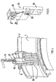
- rotor rotors of a synchronous machine shown in detail are rectangular parallelepiped 25 to fix, which alternately form a magnetic north and a magnetic south pole.
- a device 3 by means of which at the same time a total of four such magnets can be attached to the carrier surface 1 at a predetermined tangential distance, serves for fastening.
- the fastening device 3 comprises a form element 4 which can be placed on the carrier surface 1 and which is stiffened on its side facing away from the carrier surface 1 by ribs 5 and 6 and, as explained below, forms casting molds together with the carrier surface 1.
- the mold element 4 is mounted pivotably about a rotation axis 7 on a holding device 8 connected to the rotor ring 2. About screws 9 and 10, the distance between the mold element 4 and the support surface 1 can be varied.
- Fig. 2 which shows the side of the element 4 facing the support surface 1, reveals four compartments 11 each for insertion of a permanent magnet 25.
- the permanent magnets 25 consist of sections 12, which are arranged in thirteen rows and four columns, so that each permanent magnet 25 is composed of fifty-two sections 12 in the relevant embodiment.
- the open to the support surface 1 compartments 11 are closed only on its underside by a boundary wall 14. At the top they are open. At the bottom 22 of the compartments 11 a Teflon coating is provided.
- Fig. 4 shown arrangement of the formula element 4 sections 12 can be inserted into four, formed by the compartments 11 and the support wall 1 chambers by means of a motor-driven insertion device 15.
- the insertion device 15 has a slide 16 for a total of eight sections. Through windows 17 in a cover 20, the portions can be placed on the slide 16 in a starting position for the insertion operation, wherein the starting positions are offset in the insertion direction to each other, so that the placement of the sections in the starting position is not hindered by mutual repulsion.
- a lower portion 18 of the insertion device 15 is used for connection with the fastening device 3.
- a motor-driven slide 19 moves the arranged in the initial position four sections 12 via driver 21 in the direction of the mold element 4, wherein the sections held by the cover 20 on the slide 16 become.
- a total of 4992 sections are to be attached to the circumference of the rotor ring 2, which form permanent magnets or poles composed of respectively fifty-two sections.
- the fastening device 3 is fixed in the required position on the rotor ring 2 and in the in the Fig. 1 and 4 brought shown pivot position.
- a desired distance between the mold element 4 and the support wall 1 can be produced.
- Eight sections can be introduced at the same time by means of the insertion device 15 in the chambers formed by compartments 11 and the support wall 1. Reference magnets on the opposite side of the windows 17 of the slide 16 (not shown) ensure that the sections 12 can be arranged only in the correct polarity in the starting position on the slide 16.
- the slide 16 formed from several individual tracks is made of non-soft magnetic material. During the advancement of the sections 12 on the slide, therefore, no frictional forces due to attraction of the sections are to be overcome against the slide. At the transition to the compartments 11 and chambers stops 26 are formed by which the sections 12 are aligned for simultaneous entry into the chambers in a straight line. The alignment could alternatively or in addition also take place in that an end portion of the slideway is made of soft magnetic material.
- the molded part 4 consists of a soft magnetic material and thus a magnetic inference to the molding.
- the force of attraction in the direction of the support surface could be completely overcome and even an attractive force can be generated in the direction of the molded part.
- the mold element 4 is further lowered by means of the adjusting screws 9 and 10 on the support surface 2, wherein (not shown) elastomer seals seal by the mold part 4 and the support wall formed molds.
- the cuboid portions 12 abut with two side edges against the slightly rounded support surface 2, wherein between the sections and the support surface in each case a gap is formed. Further, existing gaps between the side surfaces of the outer portions and the webs 13, which are slightly conical. Also, the Teflon-coated bottom surfaces 22 of the compartments 11 have a small distance from the side facing away from the support surface 1 of the sections 12.
- a liquid adhesive is now filled under slight pressure.
- the adhesive rises slowly in said gaps and spaces.
- the increase of the adhesive is promoted by indicated at 23 longitudinal grooves in the sections 12. Through the longitudinal grooves and air can escape, which emerges upwards.
- transversely extending grooves may be formed in the support surface 1. The filling of adhesive is stopped when the adhesive level exceeds the upper ends of the uppermost portions.
- the mold element 4 After curing, the mold element 4 is pivoted about the axis of rotation 7 under demolding of the four permanent magnets 25.
- the permanent magnets are not only glued to the support surface 1 but almost completely embedded in the cured adhesive and protected from corrosion.
- the demolding is made possible by the Teflon coating on the bottom 22 of the compartments 11 and by applying release agent on the flanks of the webs 13 and the boundary wall 14.
- the Teflon coating ensures that the sections 12 can slide smoothly when inserted into the mold.
- a hammer-like tool For arranging the sections 12 in the starting position on the slide 16, a hammer-like tool can be used, the head of which consists of a soft magnetic material with a non-magnetizable coating.
- the thickness of the coating may be selected to provide a desired force of attraction between the section and the hammerhead.
- the bonded to the support surface 1 magnetic poles can be additionally secured by a bandage or other suitable cover against loosening.
Landscapes
- Engineering & Computer Science (AREA)
- Power Engineering (AREA)
- Manufacturing & Machinery (AREA)
- Permanent Field Magnets Of Synchronous Machinery (AREA)
- Manufacture Of Motors, Generators (AREA)
Claims (15)
- Procédé pour la fixation d'aimants permanents (25), formant des pôles magnétiques, sur une surface porteuse (1) du rotor (2) d'une machine électrique, dans lequel on forme, par application d'un élément de moule (4) sur la surface porteuse (1), un moule de coulée, dans lequel la cavité de moulage du moule de coulée formé est limitée sur un côté par la surface porteuse (1), on agence un aimant permanent (25) dans une position souhaitée dans le moule de coulée formé, et on remplit dans le moule de coulée formé un agent collant durcissable, dans lequel l'agent collant remplit les intervalles formés entre l'élément permanent (25) et la paroi de la cavité de moulage en collant l'aimant permanent (25) avec la surface porteuse (1),
caractérisé en ce que
l'aimant permanent (25) est introduit dans le moule de coulée formé, pour faciliter l'agencement dans la position après application de l'élément de moule (4) sur la surface porteuse (1), et il est maintenu par référence à la surface porteuse (1). - Procédé selon la revendication 1,
caractérisé en ce que l'agent collant est rempli depuis le dessous dans le moule de coulée ouvert en haut. - Procédé selon la revendication 1 ou 2,
caractérisé en ce que l'aimant permanent (25) est introduit depuis le haut dans le moule de coulée ouvert en haut. - Procédé selon la revendication 3,
caractérisé en ce que l'aimant permanent (25) est assemblé dans le moule de coulée à partir de morceaux partiels (12) par introduction des morceaux partiels (12) dans le moule de coulée. - Procédé selon l'une des revendications 1 à 4,
caractérisé en ce que l'élément de moule (4) est fabriqué en un matériau magnétique doux et ainsi par fermeture d'un circuit magnétique avec l'élément de moule (4) on réduit la force d'attraction dirigée vers la surface porteuse (1) et agissant sur l'aimant permanent (25) ou respectivement sur les morceaux partiels (12). - Procédé selon l'une des revendications 1 à 5,
caractérisé en ce que l'aimant permanent (25) ou respectivement les morceaux partiels est/sont introduit(s) dans le moule de coulée avec l'aide d'un moyen d'introduction (15) de préférence entraîné par moteur. - Procédé selon la revendication 6,
caractérisé en ce que plusieurs morceaux partiels (12) à introduire dans le moule de coulée sont agencés sur une voie de coulissement (16) du dispositif d'introduction, en décalage les uns par rapport aux autres en direction d'introduction, dans une position de départ pour l'opération d'introduction. - Procédé selon la revendication 6 ou 7,
caractérisé en ce que l'on agence dans les positions de départ des aimants de référence qui, par répulsion, empêchent l'agencement de morceaux partiels dans la position de départ avec une polarité erronée. - Procédé selon l'une des revendications 1 à 8,
caractérisé en ce que l'élément de moule (8) est fixé sur le rotor (2) avec possibilité de pivotement autour d'un axe d'articulation (7), et l'élément de moule (14) est soulevé, pour le démoulage, par pivotement depuis la surface porteuse et depuis l'aimant permanent (25) intégré par moulage. - Procédé selon l'une des revendications 1 à 9,
caractérisé en ce que l'introduction des aimants permanents (25) ou respectivement des morceaux partiels (12) a lieu alors que l'élément de moule (4) est à faible distance de la surface porteuse (1) et l'élément de moule (4) est ensuite appliqué contre la surface porteuse (1) en actionnant un dispositif de réglage de distance (9, 10) et en étanchant la cavité de moulage. - Procédé selon l'une des revendications 1 à 10,
caractérisé en ce que l'aimant permanent (25) et/ou la surface porteuse (1) est doté(e) de rainures (28) dans lesquelles l'agent collant peut s'écouler et/ou l'air qui s'échappe peut s'écouler. - Rotor (2) d'une machine électrique, avec une surface porteuse (1) sur laquelle sont rapportés des aimants permanents (25) formant des pôles magnétiques, dans lequel les aimants permanents (25) sont reliés avec la surface porteuse (1) par un agent collant durcissable qui est coulé dans un moule de coulée qui reçoit les aimants permanents (25) et la cavité de moulage est limitée sur un côté par la surface porteuse (1), en remplissant les espaces intermédiaires entre l'aimant permanent et la paroi de la cavité de moulage,
caractérisé en ce que
les aimants permanents (25) sont respectivement constitués d'une pluralité de morceaux partiels (12). - Élément de moule pour la fixation d'aimants permanents (25) formant des pôles magnétiques sur une surface porteuse (1) d'un rotor (2) d'une machine électrique, qui est prévu, en l'appliquant contre la surface porteuse (1), pour former un moule de coulée dont la cavité de moulage est limitée sur un côté par la surface porteuse (1),
caractérisé en ce que
l'élément de moule (4) comporte, pour la réception des aimants permanents (25), des surfaces qui sont ouvertes au niveau de leur côté supérieur, de sorte que le moule de coulée formé en agençant l'élément de moule (4) sur la surface porteuse (1) est ouvert pour l'introduction des aimants permanents (25). - Élément de moule selon la revendication 13,
caractérisé en ce que l'élément de moule (4) est réalisé en un matériau magnétique doux. - Élément de moule selon la revendication 13 ou 14,
caractérisé en ce que l'élément de moule (4) est susceptible d'être fixé sur le rotor avec possibilité de pivotement autour d'un axe d'articulation (7) et l'élément de moule, pour le démoulage, est susceptible d'être soulevé par pivotement depuis la surface porteuse (1) et depuis l'aimant permanent (25) intégré par moulage.
Applications Claiming Priority (1)
| Application Number | Priority Date | Filing Date | Title |
|---|---|---|---|
| DE102006044268A DE102006044268A1 (de) | 2006-09-20 | 2006-09-20 | Verfahren zur Befestigung Magnetpole bildender Permanentmagneten am Läufer einer elektrischen Maschine |
Publications (3)
| Publication Number | Publication Date |
|---|---|
| EP1903665A2 EP1903665A2 (fr) | 2008-03-26 |
| EP1903665A3 EP1903665A3 (fr) | 2011-02-16 |
| EP1903665B1 true EP1903665B1 (fr) | 2016-02-24 |
Family
ID=38521150
Family Applications (1)
| Application Number | Title | Priority Date | Filing Date |
|---|---|---|---|
| EP07017625.0A Active EP1903665B1 (fr) | 2006-09-20 | 2007-09-08 | Procédé de fixation des pôles magnétiques en aimants sur le rotor d'une machine électrique, rotor et moule de fixation des aimants |
Country Status (4)
| Country | Link |
|---|---|
| EP (1) | EP1903665B1 (fr) |
| CN (1) | CN101159399B (fr) |
| DE (1) | DE102006044268A1 (fr) |
| ES (1) | ES2568930T3 (fr) |
Families Citing this family (12)
| Publication number | Priority date | Publication date | Assignee | Title |
|---|---|---|---|---|
| EP2192674A1 (fr) * | 2008-11-28 | 2010-06-02 | ThyssenKrupp Elevator AG | Procédé destiné à l'application d'aimants |
| CN102013770B (zh) * | 2010-09-30 | 2012-10-03 | 江苏新誉重工科技有限公司 | 外转子永磁电机永磁体的密封装置及密封方法 |
| CN102611258B (zh) * | 2012-03-20 | 2014-12-10 | 精进百思特电动(上海)有限公司 | 一种磁钢装配机 |
| CN102710071B (zh) * | 2012-06-19 | 2014-11-05 | 新疆金风科技股份有限公司 | 一种风力发电机转子的制造方法 |
| CN102780332A (zh) * | 2012-07-18 | 2012-11-14 | 广东通鑫起重机科技有限公司 | 永磁电机转子磁钢固定方法 |
| CN103066772B (zh) * | 2012-12-26 | 2015-04-01 | 南车株洲电机有限公司 | 一种永磁电机磁钢装配工装 |
| CN104467225B (zh) * | 2014-11-19 | 2017-09-12 | 新疆金风科技股份有限公司 | 转子的磁极模块及其装配方法和转子 |
| CN105119430A (zh) * | 2015-08-26 | 2015-12-02 | 抚顺天工元科技有限责任公司 | 一种集中绕组结构定子铁芯的装配设备及装配方法 |
| CN109962587A (zh) * | 2017-12-25 | 2019-07-02 | 上海铼钠克数控科技股份有限公司 | 磁板治具 |
| CN110601398B (zh) * | 2019-08-14 | 2020-12-11 | 浙江大学 | 磁极固定装置及其磁极模组安装方法 |
| CN111817514A (zh) * | 2020-07-28 | 2020-10-23 | 龙城电装(常州)有限公司 | 一种电机转子制造工艺 |
| EP4195460A1 (fr) | 2021-12-07 | 2023-06-14 | Siemens Gamesa Renewable Energy A/S | Rotor pour une machine électrique à aimant permanent |
Family Cites Families (11)
| Publication number | Priority date | Publication date | Assignee | Title |
|---|---|---|---|---|
| DE951022C (de) * | 1954-12-08 | 1956-10-18 | Bosch Gmbh Robert | Wechselstromgenerator, insbesondere Schwungmagnet- oder Schwunglichtmagnetzuender |
| US3368275A (en) * | 1962-07-03 | 1968-02-13 | Syncro Corp | Casting, machining, and assembling a magnetic motor ring structure |
| DE3614191A1 (de) * | 1985-06-27 | 1987-01-08 | Man Technologie Gmbh | Verfahren zur bildung einer oberflaeche hoher guete auf einem bauteil |
| GB2217924B (en) | 1988-04-25 | 1992-10-07 | Matsushita Electric Works Ltd | Permanent magnet rotor |
| IT1232425B (it) | 1989-07-28 | 1992-02-17 | Techfab Motori Per Automazione | Procedimento per il fissaggio di magneti permanenti sul rotore di motori elettrici senza spazzole e prodotto relativo |
| FR2707813B1 (fr) * | 1993-07-16 | 2000-12-29 | Mitsuba Electric Mfg C | Rotor de magnéto-générateur et procédé pour sa fabrication. |
| JPH1155881A (ja) * | 1997-07-28 | 1999-02-26 | Sankyo Seiki Mfg Co Ltd | 永久磁石の取付方法 |
| JP2001238375A (ja) * | 2000-02-22 | 2001-08-31 | Moric Co Ltd | 永久磁石界磁モータおよび永久磁石の固着方法 |
| JP2002325403A (ja) * | 2001-04-27 | 2002-11-08 | Mitsubishi Electric Corp | 磁石発電機、磁石発電機の製造方法及び磁石発電機製造用の樹脂モールド金型 |
| US7262526B2 (en) * | 2002-06-20 | 2007-08-28 | Kabushiki Kaisha Toshiba | Rotor for permanent magnet motor of outer rotor type |
| DE10319188A1 (de) | 2003-04-29 | 2004-11-18 | Robert Bosch Gmbh | Elektrische Maschine mit Permanentmagnet |
-
2006
- 2006-09-20 DE DE102006044268A patent/DE102006044268A1/de not_active Withdrawn
-
2007
- 2007-09-08 ES ES07017625.0T patent/ES2568930T3/es active Active
- 2007-09-08 EP EP07017625.0A patent/EP1903665B1/fr active Active
- 2007-09-20 CN CN200710153770XA patent/CN101159399B/zh active Active
Also Published As
| Publication number | Publication date |
|---|---|
| EP1903665A2 (fr) | 2008-03-26 |
| CN101159399A (zh) | 2008-04-09 |
| EP1903665A3 (fr) | 2011-02-16 |
| DE102006044268A1 (de) | 2008-04-03 |
| CN101159399B (zh) | 2012-04-18 |
| ES2568930T3 (es) | 2016-05-05 |
Similar Documents
| Publication | Publication Date | Title |
|---|---|---|
| EP1903665B1 (fr) | Procédé de fixation des pôles magnétiques en aimants sur le rotor d'une machine électrique, rotor et moule de fixation des aimants | |
| EP1826889B1 (fr) | Méthode et dispositif pour monter des aimants | |
| DE102012207243A1 (de) | Positionierung eines Dauermagneten in einem Rotor oder Stator | |
| DE102004020852B4 (de) | Eingussdübel | |
| DE3211810C2 (de) | Halter für eine elektrische Zahnbürste | |
| DE19618959A1 (de) | Seitenanguß-Spritzgußvorrichtung mit radial angebrachten Angußeinsätzen | |
| AT506606A1 (de) | Spritzgiesswerkzeug | |
| EP3000571B1 (fr) | Dispositif de fabrication d'elements de formage en beton | |
| DE102017215528A1 (de) | Napf oder Napfstreifen und Verfahren zu seiner Herstellung | |
| EP0631741B1 (fr) | Procédé pour la fabrication d'un bâton adhésif et dispositif de mise en oeuvre de ce procédé | |
| DE102017010559A1 (de) | Interdentalreiniger und Spritzgussvorrichtung zur Herstellung eines Interdentalreinigers | |
| DE102014203078A1 (de) | Vorrichtung zum Einbringen einer Dübelmasse in eine Öffnung | |
| DE102006028816A1 (de) | Verfahren zur Herstellung von Spritzgussteilen mit integrierter flexibler Leiterplatte | |
| DE19720060C1 (de) | Haltevorrichtung für ein zahntechnisches Arbeitsmodell | |
| DE19810612A1 (de) | Haftmagnetleiste | |
| DE4331148A1 (de) | Dublierküvette und Verfahren zum Dublieren von Meistermodellen | |
| DE10224117A1 (de) | Kunststoffdübel | |
| DE202006007425U1 (de) | Vorrichtung zum Vermischen einer Binder- und einer Härter-Komponente zur Herstellung einer gebrauchsfertigen Spachtelmasse | |
| EP1623811B1 (fr) | Moule d'injection pour produire des pièces en matière plastique, en particulier moule d'injection pour produire un angle de connexion entre des profilés en matière plastique | |
| AT224606B (de) | Werkzeug zur Herstellung von Bürsten-, Besen- und Pinselwaren | |
| EP1409796B1 (fr) | Procede pour la production d'une couverture de puits amortie | |
| EP0673738B1 (fr) | Evier moulé à encastrer avec pièce d'insertion, et procédé pour sa fabrication | |
| DE102024130545A1 (de) | Abdichtsystem an Durchbrechungen in Formwerkzeugen oder Schalungen für die Fertigung von mit textilen Gebilden verstärkten vorgespannten Betonbauteilen | |
| DE102006010392A1 (de) | Befestigungs-Vorrichtung | |
| DE835529C (de) | Verfahren und Vorrichtung zum Aufbringen der Lochscheiben auf die Kernstifte von Vulkanisierformen |
Legal Events
| Date | Code | Title | Description |
|---|---|---|---|
| PUAI | Public reference made under article 153(3) epc to a published international application that has entered the european phase |
Free format text: ORIGINAL CODE: 0009012 |
|
| AK | Designated contracting states |
Kind code of ref document: A2 Designated state(s): AT BE BG CH CY CZ DE DK EE ES FI FR GB GR HU IE IS IT LI LT LU LV MC MT NL PL PT RO SE SI SK TR |
|
| AX | Request for extension of the european patent |
Extension state: AL BA HR MK YU |
|
| RAP1 | Party data changed (applicant data changed or rights of an application transferred) |
Owner name: VENSYS ENERGY AG |
|
| PUAL | Search report despatched |
Free format text: ORIGINAL CODE: 0009013 |
|
| AK | Designated contracting states |
Kind code of ref document: A3 Designated state(s): AT BE BG CH CY CZ DE DK EE ES FI FR GB GR HU IE IS IT LI LT LU LV MC MT NL PL PT RO SE SI SK TR |
|
| AX | Request for extension of the european patent |
Extension state: AL BA HR MK RS |
|
| 17P | Request for examination filed |
Effective date: 20110816 |
|
| AKX | Designation fees paid |
Designated state(s): DE ES FR GB IT |
|
| GRAP | Despatch of communication of intention to grant a patent |
Free format text: ORIGINAL CODE: EPIDOSNIGR1 |
|
| RIC1 | Information provided on ipc code assigned before grant |
Ipc: H02K 7/18 20060101ALN20150814BHEP Ipc: H02K 15/12 20060101ALN20150814BHEP Ipc: H02K 1/27 20060101ALN20150814BHEP Ipc: H02K 15/03 20060101AFI20150814BHEP |
|
| INTG | Intention to grant announced |
Effective date: 20150921 |
|
| GRAS | Grant fee paid |
Free format text: ORIGINAL CODE: EPIDOSNIGR3 |
|
| GRAA | (expected) grant |
Free format text: ORIGINAL CODE: 0009210 |
|
| AK | Designated contracting states |
Kind code of ref document: B1 Designated state(s): DE ES FR GB IT |
|
| REG | Reference to a national code |
Ref country code: GB Ref legal event code: FG4D Free format text: NOT ENGLISH |
|
| REG | Reference to a national code |
Ref country code: DE Ref legal event code: R096 Ref document number: 502007014569 Country of ref document: DE |
|
| REG | Reference to a national code |
Ref country code: ES Ref legal event code: FG2A Ref document number: 2568930 Country of ref document: ES Kind code of ref document: T3 Effective date: 20160505 |
|
| REG | Reference to a national code |
Ref country code: FR Ref legal event code: PLFP Year of fee payment: 10 |
|
| REG | Reference to a national code |
Ref country code: DE Ref legal event code: R097 Ref document number: 502007014569 Country of ref document: DE |
|
| PLBE | No opposition filed within time limit |
Free format text: ORIGINAL CODE: 0009261 |
|
| STAA | Information on the status of an ep patent application or granted ep patent |
Free format text: STATUS: NO OPPOSITION FILED WITHIN TIME LIMIT |
|
| 26N | No opposition filed |
Effective date: 20161125 |
|
| REG | Reference to a national code |
Ref country code: FR Ref legal event code: PLFP Year of fee payment: 11 |
|
| REG | Reference to a national code |
Ref country code: FR Ref legal event code: PLFP Year of fee payment: 12 |
|
| REG | Reference to a national code |
Ref country code: FR Ref legal event code: PLFP Year of fee payment: 16 |
|
| PGFP | Annual fee paid to national office [announced via postgrant information from national office to epo] |
Ref country code: DE Payment date: 20250828 Year of fee payment: 19 |
|
| PGFP | Annual fee paid to national office [announced via postgrant information from national office to epo] |
Ref country code: GB Payment date: 20250923 Year of fee payment: 19 |
|
| PGFP | Annual fee paid to national office [announced via postgrant information from national office to epo] |
Ref country code: FR Payment date: 20250826 Year of fee payment: 19 |
|
| PGFP | Annual fee paid to national office [announced via postgrant information from national office to epo] |
Ref country code: IT Payment date: 20250930 Year of fee payment: 19 |
|
| PGFP | Annual fee paid to national office [announced via postgrant information from national office to epo] |
Ref country code: ES Payment date: 20251020 Year of fee payment: 19 |