EP1903737B1 - Adaptation de schéma de modulation dans les systèmes de communication sans-fil à une porteuse - Google Patents
Adaptation de schéma de modulation dans les systèmes de communication sans-fil à une porteuse Download PDFInfo
- Publication number
- EP1903737B1 EP1903737B1 EP20060254656 EP06254656A EP1903737B1 EP 1903737 B1 EP1903737 B1 EP 1903737B1 EP 20060254656 EP20060254656 EP 20060254656 EP 06254656 A EP06254656 A EP 06254656A EP 1903737 B1 EP1903737 B1 EP 1903737B1
- Authority
- EP
- European Patent Office
- Prior art keywords
- modulation scheme
- constellation point
- transmission signal
- available
- transmitter
- Prior art date
- Legal status (The legal status is an assumption and is not a legal conclusion. Google has not performed a legal analysis and makes no representation as to the accuracy of the status listed.)
- Not-in-force
Links
Images






Classifications
-
- H—ELECTRICITY
- H04—ELECTRIC COMMUNICATION TECHNIQUE
- H04L—TRANSMISSION OF DIGITAL INFORMATION, e.g. TELEGRAPHIC COMMUNICATION
- H04L27/00—Modulated-carrier systems
- H04L27/0008—Modulated-carrier systems arrangements for allowing a transmitter or receiver to use more than one type of modulation
-
- H—ELECTRICITY
- H04—ELECTRIC COMMUNICATION TECHNIQUE
- H04L—TRANSMISSION OF DIGITAL INFORMATION, e.g. TELEGRAPHIC COMMUNICATION
- H04L27/00—Modulated-carrier systems
- H04L27/32—Carrier systems characterised by combinations of two or more of the types covered by groups H04L27/02, H04L27/10, H04L27/18 or H04L27/26
- H04L27/34—Amplitude- and phase-modulated carrier systems, e.g. quadrature-amplitude modulated carrier systems
- H04L27/3405—Modifications of the signal space to increase the efficiency of transmission, e.g. reduction of the bit error rate, bandwidth, or average power
- H04L27/3411—Modifications of the signal space to increase the efficiency of transmission, e.g. reduction of the bit error rate, bandwidth, or average power reducing the peak to average power ratio or the mean power of the constellation; Arrangements for increasing the shape gain of a signal set
-
- H—ELECTRICITY
- H04—ELECTRIC COMMUNICATION TECHNIQUE
- H04L—TRANSMISSION OF DIGITAL INFORMATION, e.g. TELEGRAPHIC COMMUNICATION
- H04L27/00—Modulated-carrier systems
- H04L27/32—Carrier systems characterised by combinations of two or more of the types covered by groups H04L27/02, H04L27/10, H04L27/18 or H04L27/26
- H04L27/34—Amplitude- and phase-modulated carrier systems, e.g. quadrature-amplitude modulated carrier systems
- H04L27/36—Modulator circuits; Transmitter circuits
- H04L27/362—Modulation using more than one carrier, e.g. with quadrature carriers, separately amplitude modulated
- H04L27/364—Arrangements for overcoming imperfections in the modulator, e.g. quadrature error or unbalanced I and Q levels
-
- H—ELECTRICITY
- H04—ELECTRIC COMMUNICATION TECHNIQUE
- H04B—TRANSMISSION
- H04B1/00—Details of transmission systems, not covered by a single one of groups H04B3/00 - H04B13/00; Details of transmission systems not characterised by the medium used for transmission
- H04B1/02—Transmitters
- H04B1/04—Circuits
- H04B1/0475—Circuits with means for limiting noise, interference or distortion
Definitions
- the present invention relates to modulation scheme adaptation in single carrier frequency-division wireless communication systems.
- SC-FDMA Single-carrier frequency-division multiple-access
- UE user equipment
- node-B base station
- LTE long term evolution
- UMTS Universal Mobile Telecommunications System
- UTRAN Universal Mobile Telecommunications System
- SC-FDMA with cyclic prefix is capable of achieving uplink inter-user orthogonality and efficient frequency-domain equalisation at the receiver side. Further information on SC-FDMA can be found, for example, in 3GPP TR 25,814 v.1.2.2. (2006-3), 3 rd Generation Partnership Project; Technical Specification Group Radio Access Network; Physical Layer Aspects for Evolved UTRA, section 9.1.
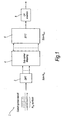
- FIG. 1 of the accompanying drawings shows parts of a transmitter 1 adapted for use in a SC-FDMA wireless communication system.
- the transmitter 1 comprises a discrete Fourier transform (DFT) unit 2, a sub-carrier mapping unit 4, an inverse fast Fourier transform (IFFT) unit 6 and a cyclic prefix (CP) insertion unit 8.
- DFT discrete Fourier transform
- IFFT inverse fast Fourier transform
- CP cyclic prefix
- the DFT unit 2 receives N TX symbols which have been subject to coding at a rate R and modulation in accordance with a particular modulation scheme, for example QPSK or 16QAM.
- the DFT unit 2 generates DFT output signals based on the N TX symbols and supplies these DFT output signals to the sub-carrier mapping unit 2.
- the sub-carrier mapping unit 2 determines which part of the spectrum is used for transmission by inserting a suitable number of zeros in sub-carrier positions that will not be used.
- the mapping carried out by the sub-carrier mapping unit 4 may be a localised mapping, i.e. a mapping in which the DFT output signals are mapped to consecutive sub-carriers.
- the sub-carrier mapping unit 4 may apply a distributed mapping, in which the DFT output signals are mapped in a distributed manner to different non-consecutive sub-carriers.
- the sub-carrier mapping unit 4 outputs mapped DFT signals corresponding respectively to the different sub-carriers to the IFFT unit 6.
- the IFFT unit 6 performs IFFT processing of size N FFT on the mapped DFT signals to produce a series of time domain symbols. These time domain symbols are supplied to the CP insertion unit 8 which inserts a cyclic prefix (CP) at the beginning of each symbol. This cyclic prefix is inserted to prevent intersymbol interference whilst preserving the orthogonality of the carriers.
- CP cyclic prefix
- the elements shown in Figure 1 operate in the digital domain. After the insertion of the cyclic prefix, the time domain symbols including the cyclic prefixes are then converted into an analog signal by a digital-to-analog converter (DAC) (not shown) and are then up-converted into radio-frequency (RF) signals by an RF block (not shown).
- DAC digital-to-analog converter
- RF radio-frequency
- the RF signal is transmitted by the transmitter to a receiver (e.g. a node B) via a radio channel.
- SC systems have the advantage of low peak-to-average power ratio (PAPR), when used in the uplink (i.e. when the transmitter is part of a UE) a major problem is limited available amplifier back-off (i.e. low efficient clipping level).
- PAPR peak-to-average power ratio
- an enhanced circular QAM modulation scheme may achieve a better PAPR level than a rectangular QAM modulation but its performance in a deep fade may be poor compared to that of the rectangular QAM scheme.
- US6748021 discloses a cellular radio communication system for transmitting data over a plurality of transmission links comprising:a generator for producing a modulated signal by applying a modulation scheme to data to be transmitted across a transmission link; an amplifier having a non-linear mode of amplification and a linear mode of amplification; and a processor for determining the quality of said transmission link, wherein a constant envelope modulation scheme and said non-linear mode of amplification is used for transmitting said data when said quality determination falls below a threshold, and a second modulation scheme and said linear mode of amplification is used for transmitting said data when said quality determination exceeds said threshold.
- US2002193078 discloses a communication system having remote power amplifier linearization, said system comprising:at least one user radio having a power amplifier linearizer that applies a transfer function to a modulated data stream, is coupled to a power amplifier, and is configured to transmit a communication signal generated by said power amplifier of said user radio; and a hub radio configured to receive said communication signal transmitted from said at least one user radio, to generate a signal quality measurement for said communication signal, to formulate commands in response to said signal quality measurement for said communication signal, and to transmit said commands; wherein said one user radio is further configured to adjust said transfer function of said power amplifier linearizer of said user radio in response to one of said commands so that said user radio power amplifier becomes remotely linearized.
- a method of adapting a modulation scheme applied by a transmitter to a transmission signal in a single-carrier frequency-division wireless communication system comprising: receiving at the transmitter N symbols to be transmitted using said transmission signal, where N is a natural number greater than or equal to 1, and, for each of a plurality of available modulation schemes, determining a constellation point of the or each said symbol if the modulation scheme concerned is applied to transmit the symbol; for each of said plurality of available modulation schemes, producing, based on the determined constellation point(s), at least one measure of an expected transmission performance if the available modulation scheme is applied to the transmission signal when transmitting said N symbols; selecting one of the available modulation schemes based on the or at least one said measure; and transmitting the N symbols using said transmission signal whilst applying thereto the selected modulation scheme.
- Such a method can provide worthwhile improvements in transmission performance without imposing a significant processing burden on the transmitter.
- At least one determined constellation point is a distorted constellation point reflecting an expected distortion of the transmission signal.
- the transmitter itself may distort the transmission signal prior to wireless transmission, e.g. in an amplifier.
- an amplifier behaviour model may be used to estimate how the amplifier will distort the transmission signal and hence obtain distorted constellation points.
- determining the distorted constellation point(s) for each said available modulation scheme comprises: generating a potential transmission signal for the modulation scheme concerned; processing the potential transmission signal to apply thereto an expected distortion; and determining the distorted constellation point(s) based on the processed potential transmission signal having said distortion.
- the transmitter may generate the transmission signal by using N-point DFT processing and M-point IFFT processing, where M is different from N, so that the transmission signal based on the received N symbols has M constellation points. This can be done to reduce the effective power of the transmission signal. In this case, producing the measures of expected transmission performance is complicated by the fact that the number of final constellation points is reduced and the amplifier behaviour model must be applied to the final constellation points, resulting in the number of distorted constellation points being different from the number of ideal (non-distorted) constellation points.
- determining the distorted constellation point(s) for each said available modulation scheme may comprise: generating a potential transmission signal for the modulation scheme concerned having M constellation points; processing the potential transmission signal having said M constellation points to apply thereto an expected distortion; and, in the transmitter, applying to the processed potential transmission signal having M distorted constellation points processing conforming substantially to processing carried out in a receiver of the wireless communication system on the received transmission signal to generate a distorted signal having N distorted constellation points.
- the processing of the potential transmission signal to apply thereto an expected distortion may comprise comparing an amplitude of the potential transmission signal with a predetermined value and, if the amplitude exceeds the predetermined value, limiting the amplitude of the potential transmission signal to said predetermined value and adjusting a phase of the potential transmission signal in dependence upon the original unlimited amplitude.
- Such processing is simple to perform but provides a useful guide to actual distortion in the transmitter.
- At least one determined constellation point is an ideal constellation point assuming that there is no distortion of the transmission signal. This can be useful for taking into account the effect of post-antenna distortion and is, of course, simple to produce.
- the or one said measure for a particular available modulation scheme is a distance measure that is dependent on a distance between the determined constellation point of the or each said symbol in the particular modulation scheme concerned and at least one other constellation point available in the particular modulation scheme concerned.
- a distance measure is relatively easy to produce without a large processing burden.
- the distances between different constellation points can be calculated in advance and held in a memory, reducing the processing burden in operation.
- Such a distance measure is preferably dependent on the respective distances between said determined constellation point and a plurality of other available constellation points neighbouring the determined constellation point. For example, the nearest 4 constellation points to the selected constellation point may be considered. This gives a reasonable guide to performance without requiring all the available constellation points to be considered. Alternatively, such a distance measure may be dependent on the respective distances between said determined constellation point and all other available constellation points in the particular modulation scheme concerned.
- the method involves determining for the or each said symbol an ideal constellation point and a distorted constellation point, and producing first and second such distance measures for a particular available modulation scheme, the first distance measure being dependent on a distance between the determined ideal constellation point of the or each said symbol in the particular modulation scheme concerned and at least one other constellation point available in the particular modulation scheme concerned, and the second distance measure being dependent on a distance between the determined distorted constellation point of the or each said symbol in the particular modulation scheme concerned and at least one other available constellation point.
- Such a probability measure would measure the probability that the distance(s) between a determined constellation point and at least one available constellation point was below (or above) some threshold. In the selecting step the selection would be based on which modulation scheme would have the best probability of having a distance below the threshold.
- the method may comprise judging if it is expected that the transmitter will distort the transmission signal significantly prior to wireless transmission and, if not, modifying the basis on which the available modulation scheme is selected in the selecting step. For example, if no distortion is expected, different measures may be used to select the modulation scheme from the measures used when distortion is expected. Alternatively, if the judgement is that no significant distortion by the transmitter is expected, the modulation scheme may be selected in the selecting step without taking into account the second distance measure mentioned above.
- the judgement may involve generating a potential transmission signal for at least one said available modulation scheme, and estimating an expected distortion of that potential transmission signal in the transmitter.
- the method may also comprise judging if it is expected that fading loss in a wireless channel from the transmitter to a receiver of said wireless communication system will be significant and, if so, modifying the basis on which the modulation scheme is selected in the selecting step. For example, if no significant fading loss is expected, different measures may be used to select the modulation scheme from the measures used when significant fading loss is expected.
- the fading loss may be estimated in the receiver. In this case the receiver may supply to the transmitter information relating to the estimated fading loss and the transmitter may modify the basis on which the modulation scheme is selected in the selecting step in dependence upon the supplied information.
- At least two such measures of expected transmission performance are produced, each based on the determined constellation point(s) but calculated in a different way from each other said measure, and the method further comprises switching between a first selection mode, in which the selection of the modulation scheme is based on a first one, or a first combination, of said measures, and a second selection mode in which the selection of the modulation scheme is based on a second one of the measures, different from said first measure, or on a second combination of the measures different from said first combination.
- the measures may be distance measures or probability measures or any other suitable measures, or any combination of these.
- the switching may be done by an operator of the transmitter but is preferably carried out dynamically in use of the transmitter, for example based on fading loss information or on pre-antenna distortion information.
- the measures are based on determined constellation points they may also be influenced by other factors, too.
- at least one said measure for each said available modulation scheme may also be dependent on an expected power loss in the transmitter if the available modulation scheme concerned is applied to the transmission signal when transmitting said N symbols. Such an expected power loss in a measure of pre-antenna distortion expected in the transmitter.
- a transmitter for use in a single-carrier frequency-division wireless communication system, the transmitter comprising: receiving means for receiving N symbols to be transmitted using a transmission signal, where N is a natural number greater than or equal to 1; constellation point determining means for determining, for each of a plurality of available modulation schemes, a constellation point of the or each said symbol if the modulation scheme concerned is applied to transmit the symbol; measure producing means for producing, for each of said plurality of available modulation schemes, at least one measure of an expected transmission performance if the available modulation scheme is applied to the transmission signal when transmitting said N symbols, the or each said measure being based on the determined constellation point(s); selecting means for selecting one of the available modulation schemes based on the or at least one said measure; and transmitting means for transmitting the N symbols using said transmission signal whilst applying thereto the selected modulation scheme.
- a third aspect of the present invention there is provided user equipment, for use in a single-carrier frequency-division wireless communication system, comprising a transmitter embodying the aforesaid second aspect of the present invention, said transmission signal being an uplink signal transmitted by the user equipment to a base station of the system.
- a single-carrier frequency-division wireless communication system comprising a transmitter embodying the aforesaid second aspect of the present invention and at least one receiver adapted to receive the transmission signal.
- the transmitter may be a UE and the receiver may be a base station (node B), or vice versa.
- a method embodying the present invention may be implemented by a processor such as a digital signal processor (DSP) operating according to a program.
- DSP digital signal processor
- an operating program which, when executed by a processor in a transmitter of a single-carrier frequency-division wireless communication system, causes the transmitter to: receive N symbols to be transmitted using a transmission signal, where N is a natural number greater than or equal to 1, and, for each of a plurality of available modulation schemes, to determine a constellation point of the or each said symbol if the modulation scheme concerned is applied to transmit the symbol; produce, for each of said plurality of available modulation schemes, based on the determined constellation point(s), at least one measure of an expected transmission performance if the available modulation scheme is applied to the transmission signal when transmitting said N symbols; select one of the available modulation schemes based on the or at least one said measure; and transmit the N symbols using said transmission signal whilst applying thereto the selected modulation scheme.
- the program may be provided by itself or on a carrier medium.
- the invention may be implemented in hardware instead of software, or in a combination of the two.
- a transmitter for use in a SC system embodying the present invention is capable of using any one of a plurality of available modulation schemes.
- the available modulation schemes may be as shown in Figures 2A and 2B .
- Figure 2A shows a circular 16 QAM modulation scheme 10 having 16 constellation points 12.
- Four constellation points are arranged in an inner ring 14 and 12 constellation points are arranged in an outer ring 16.
- a radius of the inner ring is a1 and a radius of the outer ring is a2.
- a1/a2 1/1.4.
- Figure 2B shows a rectangular 16 QAM scheme 20.
- the 16 constellation points 12 are arranged in a grid-like configuration.
- Each of the four innermost constellation points is arranged at a distance a1 from the origin in the I-direction and the Q-direction, and each of the 12 outermost constellation points 12 is arranged at a distance a 2 from the origin in the I-direction and the Q-direction.
- a1/a2 1/1.4.
- a transmitter embodying the present invention can select a different one of the available modulation schemes for each new frame of data.
- a frame of data consists of N data symbols, where N is a natural number greater than or equal to 1.
- N is chosen so that fading remains substantially constant over the time period of transmission of the frame.
- N is not particularly limited.
- N may be 16 or may be a much larger number such as 1800.
- the smaller the value of N the greater the signalling required in the SC system, so in general N should be set as high as possible, consistent with the fading being substantially constant over the frame period.
- the flowchart of Figure 3 operates on a frame-by-frame basis.
- a constellation point for each of the symbols is determined. For example, for the circular 16 QAM scheme 10 of Figure 2A one of the constellation points 12 is selected. Similarly, for the rectangular 16 QAM scheme 20 shown in Figure 2B one of the constellation points 12 is selected for each symbol.
- the determined constellation point may be an ideal constellation point taking no account of pre-antenna distortion such as amplifier clipping.
- the determined constellation point may be a distorted constellation point taking into account such pre-antenna distortion.
- both an ideal constellation point and a distorted constellation point are determined for each symbol.
- step S3 at least one measure of expected transmission performance is produced for each available modulation scheme.
- the measures are produced based on the determined constellation points in step S2. For example, a first measure may be produced based on the ideal constellation points and a second measure may be produced based on the distorted constellation points.
- step S4 one of the available modulation schemes is selected based on the measures produced in step S3.
- the way in which the selection is carried out based on the measures may be changed to take account of expected transmission characteristics, for example whether or not significant fading loss variation is expected.
- step S5 the frame of data made up of the N symbols is transmitted using the selected modulation scheme.
- step S6 it is determined whether or not there are more data symbols to be transmitted. If so, processing returns to step S1 for the next frame. Otherwise processing ends.
- a constellation point C mn is determined for each of the N data symbols of a frame of data.
- the determined constellation point C mn is an ideal constellation point, not taking account of any pre-antenna distortion in the transmitter.
- the present embodiment also applies an amplifier behaviour model to determine a distorted constellation point for each symbol, again on a per-modulation-scheme basis.
- a data frame i is made up of N symbols.
- an ideal constellation point is determined. Referring to Figure 4 , for the first available modulation scheme of Figure 2A (the circular 16 QAM scheme) a set C 1 of ideal constellation points (C 11 to C 1N ) is determined for the symbols, including an ideal constellation point C 11 for symbol 1 and an ideal constellation point C 1N for symbol N.
- a set ⁇ 1 of distorted constellation points ⁇ 11 to ⁇ 1N is determined, including a distorted constellation point ⁇ 11 for symbol 1 and a distorted constellation point ⁇ 1N for symbol N.
- a set of ⁇ 2 ideal constellation points c 21 to c 2N is determined and a set ⁇ 2 of distorted constellation points ⁇ 21 to ⁇ 2N is determined.
- the set of distorted constellation points for each available modulation scheme is then determined based on the amplifier output signal y modelled by equation (5).
- a potential transmission signal is generated for the available modulation scheme, i.e. a DFT-IFFT operation is carried out for the available candidate modulation scheme.
- the amplifier behaviour model is applied to obtain y for each potential transmittal signal x.
- the transmitter can operate either in a first selection mode or in a second selection mode.
- the first selection mode is intended to be used when both pre-antenna distortion and post-antenna distortion are significant.
- the second selection mode is intended to be used when only pre-antenna distortion is significant.
- the selection mode may be fixed in advance or it may be switched dynamically in use of the transmitter.
- the transmitter produces four different sub-metrics in this embodiment.
- the modulation scheme is selected based on a combination of a first pair of the sub-metrics and in the second selection mode the modulation scheme is selected based on a combination of a second pair of the sub-metrics.
- Each sub-metric is produced based on either the set of ideal or distorted constellation points.
- a first sub-metric a m is produced for each modulation scheme based on the ideal constellation points and for the modulation scheme concerned.
- This first sub-metric is a measure of the overall distance between the set of ideal constellation points selected for the frame and all the available constellation points in the scheme concerned.
- P is the total number of constellation points in the modulation scheme under consideration (e.g. 16 in the examples of Figures 2A and 2B ).
- this first sub-metric takes account of post-antenna distortion.
- the first sub-metric takes account of all available constellation points when calculating the overall distance, this is not essential. For example, it would be possible to take account only of the distances between a selected ideal constellation point and a cluster of neighbouring constellation points, for example the nearest four constellation points.
- a second sub-metric b m is produced for each modulation scheme based on the distorted constellation points ⁇ for the modulation scheme concerned.
- the second metric represents the overall distance between the set of distorted constellation points selected for the frame and all the available constellation points (except for the selected (ideal) constellation points, see below) for the modulation scheme concerned.
- Figure 6 is an I-Q graph illustrating how the second sub-metric b M is calculated for a particular selected distorted constellation point ⁇ .
- the calculation of the second sub-metric b m ignores the distance of each distorted constellation point from its corresponding selected (ideal) constellation point c (shown in a dotted outline in Figure 6 ). This is because the higher the distance of the distorted constellation point ⁇ from the ideal selected constellation point c the worse the performance is expected to be, whereas for other constellation points the higher the distance of the distorted constellation point the better the performance is expected to be.
- the second sub-metric b m it is not necessary in calculating the second sub-metric b m to take account of the distance of a selected distorted constellation point from all other available constellation points. For example, it would be possible simply to consider the distance of the selected distorted constellation point from a set of neighbouring available constellation points, for example the nearest four constellation points.
- a third sub-metric y m is also produced in this embodiment.
- the I-Q space may be considered to be a grid with LxL squares, where L is 10, for example. It would then be sufficient to represent any given constellation point by its grid position, i.e. the square in which it is located. This can reduce the storage capacity required and the processing burden.
- Each of the three sub-metrics a m , b m and y m is subject to a normalisation.
- a fourth sub-metric ⁇ m is calculated in dependence on the second normalised sub-metric ⁇ m of equation (12).
- This fourth sub-metric ⁇ m is intended to take into account pre-antenna distortion.
- a metric related to pre-antenna distortion is calculated for each available modulation scheme by considering the total lost power due to PAPR and inefficiency of the amplifier.
- A is the same as in equation (5) above, i.e. the amplitude limit at which the amplifier begins to clip the input signal x.
- the present embodiment is intended to be capable of selecting the modulation scheme under different conditions.
- a first condition is when both pre-antenna distortion (e.g. due to PAPR) and post-antenna distortion (e.g. due to fast-varying fading) are present.
- this first condition it is found to be effective to use a first measure, formed by adding together the first normalised sub-metric ⁇ m and the second normalised sub-metric ⁇ m , to make the selection.
- a second measure is preferably used to make the selection.
- This second measure is produced by adding together the third normalised sub-metric ⁇ m and the fourth normalised sub-metric ⁇ m . This corresponds to the second selection mode mentioned above.
- the transmitter signals to the receiver (i.e. in this case the base station) identification information identifying the selected modulation scheme m ⁇ .
- the receiver i.e. in this case the base station identification information identifying the selected modulation scheme m ⁇ .
- the signalling it is sufficient for the signalling to use a single bit which may be zero for one modulation scheme and one for the other modulation scheme. This is illustrated schematically in Figure 7 .
- the transmitter may switch selectively between using the first measure ⁇ m + ⁇ m as in equation (20) and the second measure ⁇ m + ⁇ m of equation (21). This switching between the first and second selection modes may be made dynamically in dependence upon a fading loss measure F supplied by the receiver to the transmitter, as shown schematically in Figure 8 .
- ⁇ m ⁇ max m ⁇ ⁇ m + ⁇ m F > 0
- m ⁇ max m ⁇ ⁇ m + ⁇ m F ⁇ 0
- a new value of F is supplied for each frame.
- the performance of a transmitter according to the present embodiment was simulated and compared with the performance of a first comparable transmitter (a) using circular 16 QAM exclusively for all frames and a second comparable transmitter (b) using rectangular 16 QAM exclusively for all frames.
- the channel between the transmitter and the receiver was assumed to be a AWGN channel. It was also assumed that fading coefficients are generated through complex Gaussian distributions where amplitude and phase of the generated random variables represent the fading distortions. No coding was considered.
- Figures 9 to 11 a variation of the bit error rate (BER) with signal-to-noise ratio (ratio of bit energy to noise power spectral density Eb/No expressed in dB) is considered for the present embodiment (c) and the comparable transmitters (a) and (b) under different conditions.
- the conditions for Figure 9 are a clipping level of 2.5dB and a fading variance of 0.00001.
- the conditions are a clipping level of 1.0dB and a fading variance of 0.00001.
- Figure 11 the conditions are a clipping level of 1.0dB and a fading variance of 0.05.
- the fading variance is very small, i.e. there is negligible post-antenna distortion.
- the amplifier clipping level is relatively high, whereas in the case of Figures 10 and 11 the amplifier clipping level is relatively low. In other words, the amplifier in Figure 9 is better than the amplifier in Figures 10 and 11 .
- the first embodiment described above relies on the fact that the size of the DFT processing carried out by the DFT unit 2 is the same as the size N FFT of the IFFT processing carried out by the IFFT unit 6. In that case, there is a one-to-one correspondence between the constellation points c 1 to c N of the N symbols received at the input of the DFT unit 2 and the constellation points output from the IFFT unit 6.
- the second and third sub-metrics b m and y m each require N distorted constellation points.
- the number of constellation points is deliberately reduced, compared to the original number of symbols N. This has the effect of reducing the effective transmission power.
- Figure 12A shows parts of a transmitter having no DFT-IFFT mismatch.
- N distorted constellation points ⁇ 1 to ⁇ N can be obtained by an amplifier behaviour model unit 22 based on the N ideal constellation points c 1 to c N . Accordingly, there is no difficulty in producing the second and third sub-metrics b m and y m of equations (8) and (9).
- Figure 12B shows parts of a transmitter having a DFT-IFFT mismatch.
- the transmitter converts the original N ideal constellation points c 1 to c N into M transmission constellation points q 1 to q M , where M ⁇ N. It is these transmission constellation points which will be amplified (and possibly distorted) by the pre-antenna circuitry such as the amplifier.
- the amplifier behaviour model unit 22 must consider how the pre-antenna distortion will affect these M transmission constellation points. Accordingly, the distorted constellation points q ⁇ 1 , to q ⁇ M need to be considered. However, because these are fewer in number than the original ideal constellation points, equations (8) and (9) are inapplicable.
- FIG 13 shows parts of a transmitter according to a second embodiment of the present invention, in which this mismatch problem is solved.
- the transmitter 40 comprises processing circuitry 42 having a DFT-IFFT mismatch.
- N is relatively large, for example 1,800.
- the processing circuitry 42 produces a set of M transmission constellation points q 1 to q M per frame based on the original N symbols. These are applied to a pre-antenna distortion modelling unit 44 which applies the expected pre-antenna distortion to the transmission constellation points to produce a set of M distorted transmission constellation points q ⁇ 1 to q ⁇ M .
- the distorted transmission constellation points are applied to a reverse chain unit 46.
- This reverse chain unit 46 applies to the set of M distorted transmission constellation points the same or similar processing to that which is carried out in the receiver (base station) to recover the N original constellation points from the M transmission constellation points. Details of the processing carried out in the reverse chain unit 46 will be described later with reference to Figure 14 .
- the reverse chain unit 46 therefore outputs N distorted constellation points which capture the impact of the pre-antenna distortion in the transmitter but remove the impact of mismatch. Accordingly, the N distorted constellation points output from the reverse chain unit 46 are usable in producing the second and third sub-metrics b m and y m in equations (8) and (9).
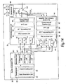
- FIG 14 shows in more detail than Figure 13 parts of the transmitter 40 of the second embodiment.
- the transmitter 40 comprises a symbol generation unit 50, an OFDM modulation unit 70, a decision unit 90, a selector 110 and a reverse chain unit 46.
- the symbol generation unit 50 comprises an encoding unit 52 and a symbol modulation unit 60.
- the encoding unit 52 comprises a data generation unit 54 and a channel coding unit 56.
- the data generation unit 54 produces a group of N symbols, which may include user data symbols and/or pilot symbols, and these N symbols are subject to channel coding by the channel coding unit 56.
- the resulting coded symbols are supplied to the symbol modulation unit 60.
- the first available modulation scheme is a square 16 QAM scheme.
- a first mapping unit 62 is included in the symbol modulation unit to carry out such square 16 QAM modulation.
- the second available modulation scheme in this example is (8,8) circular 16 QAM having a first ratio between the radii of the inner and outer rings of constellation points (radius 1).
- (8,8) means that there are 8 constellation points in each ring.
- This mapping is implemented by a second mapping unit 64 within the symbol modulation unit 60.
- the third available modulation scheme in this example is (8,8) circular 16 QAM modulation having a second radii ratio (radius 2) different from the first radii ratio.
- This modulation scheme is implemented by a third mapping unit 66 in the symbol modulation unit 60.
- the set of N symbols is subject to modulation by each of the mapping units 62, 64 and 66 to produce three sets of ideal constellation points C 1 , C 2 , C 3 corresponding respectively to the different available modulation schemes.
- the three sets of ideal constellation points are supplied to the OFDM modulation unit 70 and to the reverse chain unit 46.
- the OFDM modulation unit 70 comprises respective first, second and third metric determining units 72, 74 and 76.
- the first metric determining unit 72 subjects the set of constellation points C 1 for the first available modulation scheme to processing in accordance with equations (6) and (11) to produce a first normalised sub-metric ⁇ 1 for that modulation scheme.
- the second metric determining unit 74 carries out the processing of equations (6) and (11) on the set of constellation points C 2 for the second available modulation scheme to produce a first normalised sub-metric ⁇ 2 for that modulation scheme.
- the third metric determining unit 76 subjects the set of constellation points C 3 for the third available modulation scheme to the processing of equations (6) and (11) to produce a first normalised sub-metric ⁇ 3 for that modulation scheme.
- each set of N modulated symbols is also subjected to the usual processing to produce time-domain samples for each available modulation scheme.
- the OFDM modulation unit 70 comprises a pilot insertion unit 80, a DFT spreading unit 82, an IFFT unit 84 and a guard interval (cyclic prefix) insertion unit 86.
- the purpose and constitution of each of these units is well known in the art and is not described further here.
- a series of time domain samples TDS 1 , TDS 2 or TDS 3 is output from the OFDM modulation unit 70 to the selector 110. Because of the DFT-IFFT mismatch, the number of constellation points embodied in each series of time domain samples is M, where M ⁇ N. Thus, there are M time-domain symbols, and each time-domain symbol has a constellation point. Of course, there are several time-domain samples per time-domain symbol, but do all samples for a particular symbol have the same constellation point.
- the respective series of time domain samples TDS 1 , TDS 2 and TDS 3 for the three available modulation schemes are supplied to the reverse chain unit 46.
- the reverse chain unit 46 comprises a pre-antenna distortion modelling unit 44 which applies to each series of time-domain samples an expected pre-antenna distortion in accordance, for example, with equation (5) described above. After subjecting the time-domain samples to such expected pre-antenna distortion, the series of time domain samples for the three available modulation schemes are each subjected to processing which corresponds to that carried out in the receiver on receipt of the transmission signal to recover therefrom the original N symbols.
- the reverse chain unit 46 further comprises a guard interval removal unit 92, an FFT processing unit 96, an IDFT despreading unit 96 and a pilot removal unit 98. Again, the purpose and constitution of each of these units is well-known in the art and is not described further here.
- the result of the processing carried out by the units 92, 94, 96 and 98 is that at respective outputs of the pilot removal unit 98 a set of distorted constellation points ⁇ 1 is available for the first modulation scheme, a set ⁇ 2 of distorted constellation points is available for the second modulation scheme, and a set ⁇ 3 of distorted constellation points is available for the third modulation scheme.
- Each of these sets of distorted constellation points comprises N constellation points.
- the reverse chain unit 46 also comprises first, second and third metric determining units 100, 102 and 104.
- the first metric determining unit 100 corresponds to the first available modulation scheme and receives the set C 1 of ideal constellation points for that modulation scheme and the set ⁇ 1 of distorted constellation points for that scheme.
- the second metric determining unit 102 corresponds to the second available modulation scheme and receives the set C 2 of ideal constellation points for that modulation scheme and the set ⁇ 2 of distorted constellation points for that modulation scheme.
- the third metric determining unit 104 corresponds to the third available modulation scheme and receives the set C 3 of ideal constellation points for that modulation scheme and the set ⁇ 3 of distorted constellation points for that modulation scheme.
- Each of the first, second and third metric determining units 100, 102 and 104 carries out the processing of equations (8) and (12) on the two sets of constellation points it receives to produce for its corresponding available modulation scheme a second normalised sub-metric ⁇ 1 , ⁇ 2 or ⁇ 3 .
- the first normalised sub-metrics ⁇ 1 , ⁇ 2 and ⁇ 3 produced by the metric determining units 72, 74 and 76 respectively and the second normalised sub-metrics ⁇ 1 , ⁇ 2 and ⁇ 3 produced respectively by the metric determining units 100, 102 and 104 are supplied to the decision unit 90.
- m ⁇ is the selected modulation scheme.
- the decision unit 90 calculates a total power loss measure for the frame similar to that described above with reference to equations (14) to (17).
- T is a loss threshold.
- the transmitter operates in a first selection mode in which the modulation scheme is selected based on both the first and second sub-metrics ⁇ m and ⁇ m .
- the transmitter switches to a second selection mode in which the selection is based solely on the first sub-metrics ⁇ m .
- the decision unit 90 supplies a control signal to the selector 110 to select the series of time-domain sample corresponding to the selected modulation scheme.
- a sub-frame 200 is of duration 0.5m sec.
- the sub-frame comprises six long blocks LB#1 to LB#6 202 and two short blocks SB#1 and SB#2 204. Each block is preceded by a cyclic prefix (CP) 206.
- Short blocks 204 are used for reference signals for coherent demodulation and/or control/data transmission.
- Long blocks 202 are used for control and/or data transmission.
- the duration of the short blocks is half the duration of each of the long blocks.
- the number N of symbols transmitted per sub-frame may be, for example, 450, 900,1800, 3600, 5400 or 7200.
- a new modulation scheme could be selected only once per entire frame (i.e. multiple successive subframes) or more than once per frame but less than every sub-frame.
- Table 1 Simulation Parameters Parameters Values Carrier Frequency 2GHz Propagation conditions AWGN and 6-ray TU channel Sampling Frequency 7.679 MHz Bandwidth 5 MHz Roll-off factor of filter No used Sub frame length (TTI) 0.5ms Transmission Scheme Localised FDMA Modulation Schemes Square 16QAM, (8,8) Circular 16QAM Data Block size (Long Block Size) 6 with each occupying 300 sub carriers Pilot Block size (Short Block Size) 2 with each occupying 150 sub carriers.
- TTI Transmission Scheme Localised FDMA Modulation Schemes
- Square 16QAM (8,8) Circular 16QAM Data Block size (Long Block Size) 6 with each occupying 300 sub carriers Pilot Block size (Short Block Size) 2 with each occupying 150 sub carriers.
- the performance of different individual modulation schemes was investigated under different conditions.
- the channel between the transmitter and the receiver was assumed to be an AWGN channel. It was also assumed that no coding is performed.
- the two modulation schemes under consideration were (8,8) circular QAM and square QAM.
- Figures 16 to 19 each show a variation of a bit error rate with ratio of bit energy to noise power spectral density Eb/No in dB.
- the amplifier clipping level was assumed to be 1dB.
- the clipping level was assumed to be 4dB.
- the amplifier clipping level was assumed to be 5dB.
- the amplifier clipping level was assumed to be 6dB.
- Figures 16 to 19 show that by increasing the clipping level (i.e. providing an amplifier with a better back-off capability) the performance of both schemes improves (i.e. the BER for a given Eb/No value decreases).
- the circular QAM scheme has a better performance at high Eb/No values whereas the square QAM scheme has a better performance for lower Eb/No values.
- the square QAM scheme outperformed the circular QAM scheme at all of the Eb/No values considered.
- Figure 20 is a graph showing a variation of a block error rate (BLER) with Eb/No for (a) a transmitter according to the second embodiment of the present invention, (b) a transmitter employing exclusively (8,8) circular QAM with a radii ratio of 2.0, and (c) a transmitter employing exclusively a square QAM scheme.
- BLER block error rate
- Figure 20 it was assumed that for half of the transmission period the clipping level was 4dB (as in Figure 17 ) and for the other half of the transmission period the clipping level was 6dB (as in Figure 19 ). By varying the clipping level in this way, the intention is to simulate real conditions.
- the transmitter will have different limited power availabilities under different transmission conditions, for example depending on the position of the transmitter (UE) within a cell.
- the changes of power availability are equivalent to having different amplifier clipping levels.
- a transmitter embodying the present invention manages to follow closely the performance of the best modulation scheme at each different Eb/No value.
- the performance is almost the same as that of the superior circular QAM scheme, whilst at relatively low Eb/No values the performance follows closely that of the superior square QAM scheme.
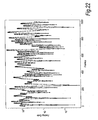
- FIG. 21 shows the assumed fading gain over a series of 1,000 frames considered for the simulation using a non-logarithmic scale.
- Figure 22 shows the same variation of fading gain over the frames but to a logarithmic scale.
- the second embodiment of the invention has three available modulation schemes and that coding is used. In all cases, two of the three available modulation schemes were (8,8) QAM schemes having different radii ratios. The third available modulation scheme was assumed to be a square QAM scheme.
- Figures 23 and 24 For the first scenario the simulation results are shown in Figures 23 and 24 . Both figures are graphs showing a variation of BLER with Eb/No per receive antenna branch. It is assumed that there is two antenna receive diversity. The clipping level is assumed to be 1dB.
- Figure 23 the coding is assumed to be 1/3 rate coding. In this case, and in all other cases in which 1/3 rate coding is assumed, the two available circular QAM schemes in a transmitter (a) according to the second embodiment of the invention are assumed to have radii ratios of 1.5 and 1.8 respectively.
- the third available modulation scheme is assumed to be square QAM.
- Figure 23 compares the performance of the transmitter (a) according to the invention with (b) a transmitter employing exclusively the 1.5 circular QAM scheme, (c) a transmitter employing exclusively the 1.8 circular QAM scheme and (d) a transmitter employing exclusively the square QAM scheme.
- the second scenario considered in the second experiment was that feedback from link adaptation is available.
- a predetermined threshold 0.2 in this second scenario
- 16QAM is not used and instead the transmitter switches to QPSK modulation.
- Figures 25 and 26 present performance results for the transmitters (a) to (d) using a coding rate of 1/3 and assuming a clipping level of 1dB.
- Figure 25 presents a variation of the block error rate with Eb/No per receive antenna branch
- Figure 26 presents a variation of the bit error rate with Eb/No per receive antenna branch.
- Figures 27 and 28 correspond to Figures 25 and 26 respectively but for a higher clipping level of 3dB.
- Figures 29 and 30 also correspond respectively to Figures 25 and 26 respectively but for a clipping level of 6dB.
- Figures 31 and 32 present performance results for the transmitters (a') to (d') using a coding rate of 1/2.
- Figure 31 presents BLER variation with Eb/No and
- Figure 31 presents BER variation with Eb/No.
- the clipping level is 3dB.
- Figures 33 and 34 correspond respectively to Figures 31 and 32 but assume a higher clipping level of 6dB.
- the transmitters (a) and (a') according to the second embodiment perform better than the comparable transmitters (b) to (d) and (b') to (d') using a single 16 QAM scheme (or switching between a single 16 QAM scheme and QPSK in the case of the second scenario).
- CM cubic metric
- PAPR peak-to-average power ratio
- the second column presents the mean value of the cubic metric over all of the simulated frames. It can be seen that the mean CM value for the transmitter (a) according to the invention is almost as good as that of the transmitter (b) using the best circular 16 QAM scheme.
- the third column in Table 2 presents the maximum CM value over the series of simulated frames. Although this maximum CM value represents only the situation for one frame and is not a measure of the overall performance for the entire transmission period, it can be seen that the maximum CM value for a transmitter (a) according to the invention is lower than that of the transmitter (d) using 16 square QAM.
- Figure 35 is a histogram showing statistics relating to the selection of the three available modulation schemes in the transmitter (a) according to the invention for different clipping levels. A series of 10,000 frames were considered. As can be seen from Figure 35 , for lower clipping levels the transmitter (a) selects the circular 1.5 QAM scheme more often than it selects the other modulation schemes. As the amplifier clipping level is increased, the frequency of selection of this circular modulation scheme declines while the frequencies of selection of the other modulation schemes increase. At a clipping level of 6dB, it can be seen that the square 16 QAM scheme is selected most frequently.
- a transmitter embodying the present invention is able to switch to the best possible modulation scheme among the available modulation schemes, achieving almost 0.5dB better performance in terms of mean cubic metric than square 16 QAM while outperforming it in terms of BLER in the case of a radio channel with fading.
Landscapes
- Engineering & Computer Science (AREA)
- Signal Processing (AREA)
- Computer Networks & Wireless Communication (AREA)
- Digital Transmission Methods That Use Modulated Carrier Waves (AREA)
- Transmitters (AREA)
Claims (20)
- Procédé d'adaptation d'un schéma de modulation appliqué par un émetteur à une signal de transmission dans un système de communication sans fil par répartition en fréquence à porteuse unique, le procédé comprenant :la réception au niveau ce l'émetteur de N symboles devant être transmis en utilisant ledit signal de transmission, où N est un nombre naturel supérieur ou égal à 1, est, pour chacun d'une pluralité de schémas de modulation disponibles, la détermination, d'un point de constellation du ou de chaque dit symbole si le schéma de modulation concerné est appliqué pour transmettre le symbole ;pour chacun de ladite pluralité de schémas de modulation disponibles, la production, sur la base du ou des points de constellation déterminés, d'au moins une mesure d'une performance de transmission escomptée si le schéma de modulation disponible est appliqué au signal de transmission lors de à transmission desdits N symboles ;la sélection d'un des schémas de modulation disponibles sur la base de la ou d'au moins une dite mesure ; etla transmission des N symboles en utilisant ladit signal de transmission tout en y appliquant le schéma de modulation sélectionné, oùla ou au moins ladite mesure pour un schéma de modulation particulier disponible est une métrique obtenue par une première métrique ou une combinaison d'une première et d'une seconde métrique, et où le procédé comprend en outre :la détermination pour le ou chaque dit symbole d'un point de constellation idéal et d'un point de constellation distordu, où le point de constellation distordu est détermine en utilisant un modèle de comportement d'amplificateur, et la production desdites première est seconde métriques pour un schéma de modulation particulier disponible, la première métrique dépendant d'une distance entre le point de constellation idéal, détermine du ou de chaque dit symbole dans le schéma de modulation particulier concerné et au moins un autre point de constellation disponible dans le schéma de modulation particulier concerné, et la seconde métrique dépendant d'une distance entre le point de constellation distordu déterminé du ou de chaque dit symbole dans le schéma de modulation particulier concerné et au moins un autre point de constellation disponible.
- Procédé selon la revendication 1, dans lequel au moins un point de constellation déterminé est un point de constellation, distordu reflétant une distorsion escomptée du signal de transmission.
- Procédé selon la revendication 2, dans lequel la détermination du ou des points de constellation distordus pour chaque dit schéma de modulation disponible comprend :la génération d'un signal de transmission potentiel pour le schéma de modulation concerné ;le traitement du signal de transmission potentiel pour y appliquer une distorsion escomptée ; etla détermination du(des) point (s) de constellation distordu (s) sur la base du signal de transmission potentiel traité ayant ladite distorsion.
- Procédé selon la revendication 2, dans lequel l'émetteur génère le signal de transmission en utilisant un traitement DFT à N point et un traitement IFFT à M point, où M est différent de N, de sorte que le signal de transmission basé sur les N symboles reçus ait M points de constellation, et la détermination du ou des points de constellation distordus pour chaque dit schéma de modulation disponible comprend :la génération d'un signal de transmission potentiel pour le schéma de modulation concerné ayant M points de constellation ;le traitement, du signal de transmission potentiel ayant lesdits M points de constellation pour y appliquer une distorsion escomptée ;dans l'émetteur, l'application au signal de transmission potentiel traité ayant M points de constellation distordus d'un traitement se conformant sensiblement au traitement effectué dans un récepteur du système de communication sans fil sur le signal de transmission reçu afin de générer un signal distordu ayant. N points de constellation distordus.
- Procédé selon la revendication 3 ou 4, dans lequel ledit traitement du signal de transmission potentiel pour appliquer une distorsion escomptée comprend la comparaison d'une amplitude du signal de transmission potentiel avec une valeur prédéterminée et, si l'amplitude dépasse la valeur prédéterminée, limiter l'amplitude du signal de transmission potentiel à ladite valeur prédéterminée et ajuster une phase du signal de transmission potentiel en fonction de l'amplitude illimitée d'origine.
- Procédé selon la revendication 2, 3, 4 ou 5, dans lequel ledit point de constellation distordu est déterminé en tenant compte de la distorsion escomptée du signal de transmission dans l'émetteur avant la transmission sans fil.
- Procédé selon l'une quelconque des revendications précédentes, dans lequel au moins un point de constellation déterminé est un point de constellation idéal en supposant qu'il n'y ait pas de distorsion du signal de transmission.
- Procédé selon l'une quelconque des revendications précédentes, dans lequel ladite métrique dépend des distances respectives entre ledit point de constellation déterminé et une pluralité d'autres points de constellation disponibles avoisinant le point de constellation déterminé.
- Procédé selon l'une quelconque des revendications précédentes, dans lequel ladite métrique dépend des distances respective entre ledit point de constellation déterminé et tous les autres points de constellation disponibles dans le schéma de modulation particulier concerné.
- Procédé selon l'une quelconque des revendications précédentes, comprenant en outre le fait de juger s'il est escompté que l'émetteur distordra le signal de transmission de manière significative avant la transmission sans fil et, si non, modifier la base sur laquelle le schéma de modulation disponible est sélectionné à l'étape de sélection.
- Procédé selon la revendication 10, dans lequel le jugement implique la génération d'un signal de transmission potentiel pour au moins un dit schéma de modulation disponible, et l'estimation d'une distorsion escomptée de ce signal de transmission potentiel dans l'émetteur.
- Procédé selon la revendication 10 ou 11 lorsque lues comme annexées à la revendication 1, dans lequel si le jugement est qu'aucune distorsion significative par l'émetteur n'est escomptée, le schéma de modulation est sélectionné à l'étape de sélection sans prendre en compte la seconde mesure de distance.
- Procédé selon l'une quelconque des revendications précédentes, comprenant en outre le fait de juger s'il est escompté qu'un affaiblissement d'évanouissement dans un canal sans fil de l'émetteur à un récepteur dudit système de communication sans fil sera significatif et, si oui, modifier la base sur laquelle le schéma de modulation est sélectionné à l'étape de sélection.
- Procédé selon la revendication 13, comprenant en outre l'estimation de l'affaiblissement d'évanouissement dans le récepteur et la fourniture du récepteur à l'émetteur d'informations relatives à l'affaiblissement d'évanouissement estimé et la modification de la base sur laquelle le schéma de modulation est sélectionné à l'étape de sélection en fonction des informations fournies.
- Procédé selon l'une quelconque des revendications précédentes, dans lequel au moins deux telles métriques sont produites, chacune basée sur le ou les points de constellation déterminés mais calculée d'une façon différente de ladite autre métrique, et le procédé comprend en outre la commutation entre un premier mode de sélection, dans lequel la sélection du schéma de modulation est basée sur une première, ou une première combinaison, desdites métriques, et un second mode de sélection dans lequel la sélection du schéma de modulation est basée sur une seconde des métriques, différente de ladite première métrique, ou sur une seconde combinaison des métriques différente de ladite première combinaison.
- Procédé selon l'une quelconque des revendications précédentes, dans lequel au moins une dite métrique pour chaque dit schéma de modulation disponible dépend également d'un affaiblissement en puissance escompté dans l'émetteur si le schéma de modulation disponible concerné est appliqué au signal de transmission lors de la transmission desdits N symboles.
- Emetteur destiné à être utilisé dans un système de communication sans fil par répartition en fréquence à porteuse unique, l'émetteur comprenant :un moyen de réception pour recevoir N symboles devant être transmis en utilisant un signal de transmission, où N est un nombre naturel supérieur ou égal à 1 ;un moyen de détermination de point de constellation pour déterminer, pour chacun d'une pluralité de schémas de modulation disponibles, un point de constellation du ou de chaque dit symbole si le schéma de modulation concerné est appliqué pour transmettre le symbole ;un moyen de production de mesure pour produire, pour chacun de ladite pluralité de schémas de modulation disponibles, au moins une mesure d'une performance de transmission escomptée si le schéma de modulation disponible est appliqué au signal de transmission lors de la transmission desdits N symboles, la ou chaque dite mesure étant basée sur le ou les points de constellation détérminés ;un moyen de sélection pour sélectionner un des schémas de modulation disponibles sur la base de la ou d'au moins une dite mesure ; etun moyen de transmission pour transmettre les N symboles en utilisant ledit signal de transmission tout en y appliquant le schéma de modulation sélectionné, oùle moyen de détermination de point de constellation est en outre adapté pour déterminer pour le ou chaque dit symbole un point de constellation idéal et un point de constellation distordu, où le point de constellation distordu est déterminé en utilisant un modèle de comportement d'amplificateur, et oùla au moins une mesure pour un schéma de modulation particulier disponible, produit par ledit moyen de production de mesure, est une métrique obtenue par une première métrique ou une combinaison d'une première et d'une seconde métrique, et oùle moyen de production de mesure est en outre adapté pour produire lesdites première et seconde métriques pour une schéma de modulation particulier disponible, la première métrique dépendant d'une distance entre le point de constellation idéal déterminé du ou de chaque dit symbole dans le schéma de modulation particulier concerné et au moins un autre point de constellation disponible dans le schéma de modulation particulier concerné, et la seconde métrique dépendant d'une distance entre le point de constellation distordu déterminé du ou de chaque dit symbole dans le schéma de modulation particulier concerné et au moins un autre point de constellation disponible.
- Equipement utilisateur, destiné à être utilisé dans un système de communication sans fil par répartition en fréquence à porteuse unique, comprenant un émetteur selon la revendication 17, ledit signal de transmission étant un signal de liaison montante transmis par l'équipement utilisateur à une station de base du système.
- Système de communication sans fil par répartition en fréquence à porteuse unique comprenant un émetteur selon la revendication 17 et au moins un récepteur adapté pour recevoir le signal de transmission.
- Programme d'exploitation qui, lorsqu'il est exécuté par un processeur dans un émetteur d'un système de communication sans fil par répartition en fréquence à porteuse unique, amène l'émetteur à :recevoir N symboles devant être transmis en utilisant un signal de transmission, où N est un nombre naturel supérieur ou égal à 1, et, pour chacun d'une pluralité de schémas de modulation disponibles, déterminer un point de constellation du ou de chaque dit symbole si le schéma de modulation concerné est appliqué pour transmettre le symbole ;produire, pour chacun de ladite pluralité de schémas de modulation disponibles, sur la base du ou des points de constellation déterminés, au moins une mesure d'une performance de transmission escomptée si le schéma de modulation disponible est appliqué au signal de transmission lors de la transmission desdits N symboles ;sélectionner un des schémas de modulation disponibles sur la base de la ou d'au moins une dite mesure ; ettransmettre les N symboles en utilisant ledit signal de transmission tout en y appliquant le schéma de modulation sélectionné, oùla au moins une dite mesure pour un schéma de modulation particulier disponible est une métrique obtenue par une première métrique ou une combinaison d'une première et d'une seconde métrique, et où,pour le ou chaque dit symbole, un point de constellation idéal et un point de constellation distordu sont déterminés, où le point de constellation distordu est déterminé en utilisant un modèle de comportement d'amplificateur, et produire lesdites première et seconde métriques pour un schéma de modulation particulier disponible, la première métrique dépendant d'une distance entre le point de constellation idéal déterminé du ou de chaque dit symbole dans le schéma de modulation particulier concerné et au moins un autre point de constellation disponible dans le schéma de modulation particulier concerné, et la seconde métrique dépendant d'une distance entre le point de constellation distordu déterminé du ou de chaque dit symbole dans le schéma de modulation particulier concerné et au moins un autre point de constellation disponible.
Priority Applications (2)
| Application Number | Priority Date | Filing Date | Title |
|---|---|---|---|
| DE200660018306 DE602006018306D1 (de) | 2006-09-07 | 2006-09-07 | Anpassung des Modulierungsschemas in Einträger-Funkkommunikationssystemen |
| EP20060254656 EP1903737B1 (fr) | 2006-09-07 | 2006-09-07 | Adaptation de schéma de modulation dans les systèmes de communication sans-fil à une porteuse |
Applications Claiming Priority (1)
| Application Number | Priority Date | Filing Date | Title |
|---|---|---|---|
| EP20060254656 EP1903737B1 (fr) | 2006-09-07 | 2006-09-07 | Adaptation de schéma de modulation dans les systèmes de communication sans-fil à une porteuse |
Publications (2)
| Publication Number | Publication Date |
|---|---|
| EP1903737A1 EP1903737A1 (fr) | 2008-03-26 |
| EP1903737B1 true EP1903737B1 (fr) | 2010-11-17 |
Family
ID=37726931
Family Applications (1)
| Application Number | Title | Priority Date | Filing Date |
|---|---|---|---|
| EP20060254656 Not-in-force EP1903737B1 (fr) | 2006-09-07 | 2006-09-07 | Adaptation de schéma de modulation dans les systèmes de communication sans-fil à une porteuse |
Country Status (2)
| Country | Link |
|---|---|
| EP (1) | EP1903737B1 (fr) |
| DE (1) | DE602006018306D1 (fr) |
Families Citing this family (2)
| Publication number | Priority date | Publication date | Assignee | Title |
|---|---|---|---|---|
| JP2012508484A (ja) * | 2008-11-04 | 2012-04-05 | ノーテル・ネットワークス・リミテッド | 無線送信のための情報ブロックの処理 |
| CN106922213B (zh) * | 2014-11-21 | 2020-06-16 | 华为技术有限公司 | 传输信息的方法、装置和设备 |
Family Cites Families (2)
| Publication number | Priority date | Publication date | Assignee | Title |
|---|---|---|---|---|
| US6748021B1 (en) * | 2000-06-22 | 2004-06-08 | Nortel Networks Limited | Cellular radio communications system |
| US7088958B2 (en) * | 2001-06-19 | 2006-08-08 | Intersil Americas Inc. | Remote power amplifier linearization |
-
2006
- 2006-09-07 DE DE200660018306 patent/DE602006018306D1/de active Active
- 2006-09-07 EP EP20060254656 patent/EP1903737B1/fr not_active Not-in-force
Also Published As
| Publication number | Publication date |
|---|---|
| EP1903737A1 (fr) | 2008-03-26 |
| DE602006018306D1 (de) | 2010-12-30 |
Similar Documents
| Publication | Publication Date | Title |
|---|---|---|
| KR102283357B1 (ko) | 무선 주파수 캐리어 집성을 위한 시스템 및 방법 | |
| US8467801B2 (en) | Channel sounding techniques for a wireless communication system | |
| EP1791313B1 (fr) | Systèmes et procédés de communication utilisant le mappage selectionné pour signaux OFDM | |
| US20160036612A1 (en) | System and method for controlling combined radio signals | |
| Baig et al. | PAPR reduction in OFDM systems: Zadoff-Chu matrix transform based pre/post-coding techniques | |
| JP4002239B2 (ja) | 直交周波数分割多重化方式の移動通信システムでピーク電力対平均電力の減少装置及び方法 | |
| Sung et al. | Adaptive bit-interleaved coded OFDM with reduced feedback information | |
| JP2009267508A (ja) | 無線通信システム並びにそれに用いる送信装置 | |
| CN102510368B (zh) | 基于幅度分布变换的无线ofdm信号峰平比抑制方法 | |
| EP1694021A1 (fr) | Emetteur MROF pour réduction de la puissance de crête | |
| Wu et al. | Hardware impairments in millimeter wave communications using OFDM and SC-FDE | |
| JP2008022230A (ja) | ピーク抑圧制御装置 | |
| JP4932641B2 (ja) | 通信装置におけるピーク電力低減装置 | |
| US7974354B2 (en) | Peak-to-average-power-ratio reduction in communication systems | |
| Inoue et al. | Throughput/ACLR performance of CF-based adaptive PAPR reduction method for eigenmode MIMO-OFDM signals with AMC | |
| CN100421438C (zh) | 选频单载波分块传输系统中的比特加载方法 | |
| EP1903737A1 (fr) | Adaptation de schéma de modulation dans les systèmes de communication sans-fil à une porteuse | |
| Chouitem | EVM based AMC for an OFDM system | |
| Frank et al. | A survey on the envelope fluctuations of DFT precoded OFDMA signals | |
| Gazda et al. | Comparative evaluation of OFDMA and SC-FDMA based transmission systems | |
| Singh et al. | PAPR reduction techniques in LTE/LTE-A systems | |
| Ishihara et al. | Comparison of SCFDE and OFDM with adaptive modulation and coding in nonlinear fading channel | |
| Aizawa et al. | Effect of peak power suppression and adaptive predistortion on power amplification of an ofcdm signal | |
| Sterba et al. | Iterative algorithm for channel re-estimation and data recovery in nonlinearly distorted OFDM systems | |
| Kim et al. | A robust companding scheme against nonlinear distortion of high power amplifiers in OFDM systems |
Legal Events
| Date | Code | Title | Description |
|---|---|---|---|
| PUAI | Public reference made under article 153(3) epc to a published international application that has entered the european phase |
Free format text: ORIGINAL CODE: 0009012 |
|
| AK | Designated contracting states |
Kind code of ref document: A1 Designated state(s): AT BE BG CH CY CZ DE DK EE ES FI FR GB GR HU IE IS IT LI LT LU LV MC NL PL PT RO SE SI SK TR |
|
| AX | Request for extension of the european patent |
Extension state: AL BA HR MK YU |
|
| 17P | Request for examination filed |
Effective date: 20080325 |
|
| AKX | Designation fees paid |
Designated state(s): DE FR GB |
|
| GRAP | Despatch of communication of intention to grant a patent |
Free format text: ORIGINAL CODE: EPIDOSNIGR1 |
|
| GRAS | Grant fee paid |
Free format text: ORIGINAL CODE: EPIDOSNIGR3 |
|
| GRAA | (expected) grant |
Free format text: ORIGINAL CODE: 0009210 |
|
| AK | Designated contracting states |
Kind code of ref document: B1 Designated state(s): DE FR GB |
|
| REG | Reference to a national code |
Ref country code: GB Ref legal event code: FG4D |
|
| REF | Corresponds to: |
Ref document number: 602006018306 Country of ref document: DE Date of ref document: 20101230 Kind code of ref document: P |
|
| PLBE | No opposition filed within time limit |
Free format text: ORIGINAL CODE: 0009261 |
|
| STAA | Information on the status of an ep patent application or granted ep patent |
Free format text: STATUS: NO OPPOSITION FILED WITHIN TIME LIMIT |
|
| 26N | No opposition filed |
Effective date: 20110818 |
|
| REG | Reference to a national code |
Ref country code: DE Ref legal event code: R097 Ref document number: 602006018306 Country of ref document: DE Effective date: 20110818 |
|
| PGFP | Annual fee paid to national office [announced via postgrant information from national office to epo] |
Ref country code: DE Payment date: 20140903 Year of fee payment: 9 |
|
| PGFP | Annual fee paid to national office [announced via postgrant information from national office to epo] |
Ref country code: GB Payment date: 20140903 Year of fee payment: 9 |
|
| PGFP | Annual fee paid to national office [announced via postgrant information from national office to epo] |
Ref country code: FR Payment date: 20140906 Year of fee payment: 9 |
|
| REG | Reference to a national code |
Ref country code: DE Ref legal event code: R119 Ref document number: 602006018306 Country of ref document: DE |
|
| GBPC | Gb: european patent ceased through non-payment of renewal fee |
Effective date: 20150907 |
|
| REG | Reference to a national code |
Ref country code: FR Ref legal event code: ST Effective date: 20160531 |
|
| PG25 | Lapsed in a contracting state [announced via postgrant information from national office to epo] |
Ref country code: DE Free format text: LAPSE BECAUSE OF NON-PAYMENT OF DUE FEES Effective date: 20160401 Ref country code: GB Free format text: LAPSE BECAUSE OF NON-PAYMENT OF DUE FEES Effective date: 20150907 |
|
| PG25 | Lapsed in a contracting state [announced via postgrant information from national office to epo] |
Ref country code: FR Free format text: LAPSE BECAUSE OF NON-PAYMENT OF DUE FEES Effective date: 20150930 |