EP1903835A2 - Appareil auditif avec dispositif de protection supplémentaire - Google Patents
Appareil auditif avec dispositif de protection supplémentaire Download PDFInfo
- Publication number
- EP1903835A2 EP1903835A2 EP07113667A EP07113667A EP1903835A2 EP 1903835 A2 EP1903835 A2 EP 1903835A2 EP 07113667 A EP07113667 A EP 07113667A EP 07113667 A EP07113667 A EP 07113667A EP 1903835 A2 EP1903835 A2 EP 1903835A2
- Authority
- EP
- European Patent Office
- Prior art keywords
- housing
- shielding
- magnetic
- hearing
- induction coil
- Prior art date
- Legal status (The legal status is an assumption and is not a legal conclusion. Google has not performed a legal analysis and makes no representation as to the accuracy of the status listed.)
- Withdrawn
Links
Images
Classifications
-
- H—ELECTRICITY
- H04—ELECTRIC COMMUNICATION TECHNIQUE
- H04R—LOUDSPEAKERS, MICROPHONES, GRAMOPHONE PICK-UPS OR LIKE ACOUSTIC ELECTROMECHANICAL TRANSDUCERS; ELECTRIC HEARING AIDS; PUBLIC ADDRESS SYSTEMS
- H04R25/00—Electric hearing aids
- H04R25/60—Mounting or interconnection of hearing aid parts, e.g. inside tips, housings or to ossicles
- H04R25/604—Mounting or interconnection of hearing aid parts, e.g. inside tips, housings or to ossicles of acoustic or vibrational transducers
-
- H—ELECTRICITY
- H04—ELECTRIC COMMUNICATION TECHNIQUE
- H04R—LOUDSPEAKERS, MICROPHONES, GRAMOPHONE PICK-UPS OR LIKE ACOUSTIC ELECTROMECHANICAL TRANSDUCERS; ELECTRIC HEARING AIDS; PUBLIC ADDRESS SYSTEMS
- H04R25/00—Electric hearing aids
- H04R25/55—Electric hearing aids using an external connection, either wireless or wired
- H04R25/554—Electric hearing aids using an external connection, either wireless or wired using a wireless connection, e.g. between microphone and amplifier or using Tcoils
-
- H—ELECTRICITY
- H04—ELECTRIC COMMUNICATION TECHNIQUE
- H04R—LOUDSPEAKERS, MICROPHONES, GRAMOPHONE PICK-UPS OR LIKE ACOUSTIC ELECTROMECHANICAL TRANSDUCERS; ELECTRIC HEARING AIDS; PUBLIC ADDRESS SYSTEMS
- H04R2225/00—Details of deaf aids covered by H04R25/00, not provided for in any of its subgroups
- H04R2225/49—Reducing the effects of electromagnetic noise on the functioning of hearing aids, by, e.g. shielding, signal processing adaptation, selective (de)activation of electronic parts in hearing aid
Definitions
- the present invention relates to a handset for a portable in / on the ear hearing with a soft magnetic housing having on an outer wall a connection device, and an electro-acoustic transducer, which is arranged in the housing and can be controlled via the connection device from the outside.
- the present invention relates to a hearing device and in particular a hearing aid with such a handset.
- this handset can also be used for other hearing devices, such as headsets, headphones and the like.
- Hearing aids are portable hearing aids that are used to care for the hearing impaired.
- different types of hearing aids such as behind-the-ear hearing aids (BTE), in-the-ear hearing aids (IDO), Concha hearing aids are provided.
- BTE behind-the-ear hearing aids
- IDO in-the-ear hearing aids
- Concha hearing aids are provided.
- the hearing aids listed by way of example are worn on the outer ear or in the ear canal.
- bone conduction hearing aids, implantable or vibrotactile hearing aids are also available on the market. The stimulation of the damaged hearing takes place either mechanically or electrically.
- Hearing aids have in principle as essential components an input transducer, an amplifier and an output transducer.
- the input transducer is usually a sound receiver, z. As a microphone, and / or an electromagnetic receiver, for. B. an induction coil.
- the output transducer is usually used as an electroacoustic transducer, z. As miniature speaker, or as an electromechanical transducer, z. B. bone conduction, realized.
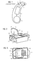
- the amplifier is usually integrated in a signal processing unit. This basic structure is shown in FIG 1 using the example of a behind-the-ear hearing aid. In a hearing aid housing 1 for Carrying behind the ear, one or more microphones 2 are installed for recording the sound from the environment.
- a signal processing unit 3 which is also integrated in the hearing aid housing 1, processes the microphone signals and amplifies them.
- the output signal of the signal processing unit 3 is transmitted to a loudspeaker or earpiece 4, which outputs an acoustic signal.
- the sound is optionally transmitted via a sound tube, which is fixed with an earmold in the ear canal, to the eardrum of the device carrier.
- the power supply of the hearing device and in particular of the signal processing unit 3 is carried out by a likewise integrated into the hearing aid housing 1 battery. 5
- an electrodynamic loudspeaker As an electroacoustic transducer, an electrodynamic loudspeaker is often used, which uses the Lorentz force as a power source.
- a voice coil drives a diaphragm, which generates the sound.
- This voice coil unintentionally emits magnetic fields to the outside, which disturb other components of the hearing device or of the hearing device.
- telemetry device which are integrated into the hearing device, affected by the strong interference of the listener with the electrodynamic coil. This is due in particular to the fact that the individual components in a hearing aid must necessarily be arranged very close to each other.
- the listeners are therefore usually in a soft magnetic housing with high magnetic permeability, which ensures the shielding of the magnetic fields embedded.
- the metal used is usually a nickel-iron alloy with about 75 to 80% nickel. Such an alloy is known by the name Mu-Metall (Mumetall®).
- Mu-Metall Mu-Metall
- a corresponding magnetically shielded electro-acoustic transducer is from the document US 4,956,868 A known. It has two housing halves with high magnetic permeability.
- the shield of a listener is usually broken on two sides, namely on the side of the sound lasses and on the side of the electrical connection (see FIG 2). For this reason disturbing magnetic fields occur on these pages despite the housing. These interference fields affect other hearing aid components in their function.
- a hearing aid is known with a handset, which is surrounded by a shielding plate or a shielding capsule.
- the hearing aid on a compensation coil, which is located in front of, next to or behind the listener. However, it is not inside the shielding capsule.
- the document describes DE 198 54 201 C2 a hearing aid with an induction coil or telecoil.
- the device also has a compensation inductor positioned so that its compensation field is directed against the magnetic field of the listener during operation of the induction coil and reduces coupling between the earpiece and the induction coil.
- the object of the present invention is thus to further reduce the magnetic interference emanating from a listener.
- this object is achieved by a handset for a portable in / on the ear hearing with a soft magnetic housing having an electrical connection means on an outer wall, and an electro-acoustic transducer which is arranged in the housing and via the connection device can be controlled from the outside, wherein a shielding device is installed in the magnetic shielding housing between the outer wall and the terminal device and the electroacoustic transducer.
- At least the part of the magnetic interference field is shielded to the outside by the shielding device in the receiver housing, which would penetrate through or on the connection device to the outside.
- the shielding means includes a magnetic shielding plate.
- a magnetic shielding plate which may also consist of a mu-metal is very inexpensive and can be mounted easily.
- the shielding device may comprise an induction coil. In this way, the interference field can be actively canceled by a corresponding opposing field.
- the induction coil may for example consist of an air coil. This has the advantage that it has a very wide dispersion.
- the induction coil can be arranged transversely to the magnetic axis of the electromagnetic transducer. This is favorable inasmuch as the working magnetic field of the electroacoustic transducer should be influenced as little as possible.
- the induction coil is connected in series with the electroacoustic transducer.
- the handset according to the invention is used in a hearing device, which furthermore has a telemetry device for electromagnetic communication with an external device.
- the telemetry device of the hearing aid can be operated relatively interference-free.
- a listener or miniature speaker of a hearing aid is shown in perspective. It is located in a housing 10 made of mu-metal, d. H. soft magnetic nickel-iron alloy of high magnetic permeability. On the front side of the receiver housing 10 is a Schallauslassstutzen 11. On the opposite side two terminal contacts 12, 13 are integrated into the housing wall. These serve for electrical connection of the electroacoustic transducer 14 located in the housing 10. This electroacoustic transducer has a winding with which an alternating magnetic field is generated.
- the magnetic interference fields of the winding of the electroacoustic transducer 14 are largely shielded by the housing 10.
- a noticeable leak results in the area of the electrical contacts 12, 13, which do not represent sufficient magnetic shielding.
- a Mu metal sheet 15 inserted between the electro-acoustic Transducer 14 and the electrical connection device, ie, the electrical contacts 12, 13, a Mu metal sheet 15 inserted.
- This has at its left and right upper corner in each case a recess 16, 17, through which the strands 18, which connect the contact points 12, 13 with the electro-acoustic transducer 14, are guided.
- FIG 2 is indicated by an arrow, as the additional shielding plate 15 is inserted into the housing 10.
- the handset is shown in a plan view with inserted shielding. From this perspective, it is easy to see how the strands 18 are guided by the recesses 16, 17 from the electroacoustic transducer 14 to the contact points 12, 13.
- the recesses 16, 17 should be kept as small as possible so that the shielding of the magnetic interference fields in the direction of the contact points 12, 13 remains as high-quality as possible.
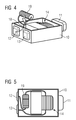
- FIG 4 and FIG 5 A second embodiment of a receiver according to the invention is shown in FIG 4 and FIG 5.
- the construction of the receiver essentially corresponds to that of FIG. 2 and FIG. 3. Accordingly, an electroacoustic transducer 14 is located in a mu-metal housing 10, of which only the bottom shell is shown in the drawing.
- the sound outlet 11 is located on the opposite side to the side with the connection points 12, 13.
- the electro-acoustic transducer 14 is electrically connected to the contact points 12, 13.
- an induction coil 19 is inserted into the housing 10 between the electroacoustic transducer 14 and the connection device with the connection points 12, 13.
- the induction coil 19 does not act as passive as the shielding plate 15, but actively to compensate for the stray field of the electro-acoustic transducer 14. To the outside, however, this compensation coil also acts like a shielding unit, so that it is generally understood by the term shielding device.
- the compensation coil 19 is designed here as an air coil. This means that it has no metal core. This has the advantage that it has a relatively high dispersion. Depending on requirements, however, it may also be completely or partially filled with a soft-magnetic core.
- FIG. 5 shows a plan view of the coil in the state installed in the housing 10. It can be seen that the compensation coil 19 is connected in series with the winding of the electroacoustic transducer 14. The compensation results from the fact that subtract the magnetic fields and thus can not be absorbed by the very sensitive telecoil. The optimal arrangement and alignment of the compensation coil must be determined individually for each handset.
- the shielding or compensation for some in-the-ear hearing aids makes it possible in the first place for telecoils or telemetry units to be integrated into the hearing aid.
Landscapes
- Engineering & Computer Science (AREA)
- Computer Networks & Wireless Communication (AREA)
- Health & Medical Sciences (AREA)
- General Health & Medical Sciences (AREA)
- Neurosurgery (AREA)
- Otolaryngology (AREA)
- Physics & Mathematics (AREA)
- Acoustics & Sound (AREA)
- Signal Processing (AREA)
- Telephone Set Structure (AREA)
- Measurement Of The Respiration, Hearing Ability, Form, And Blood Characteristics Of Living Organisms (AREA)
- Headphones And Earphones (AREA)
Applications Claiming Priority (1)
| Application Number | Priority Date | Filing Date | Title |
|---|---|---|---|
| DE102006043909A DE102006043909B3 (de) | 2006-09-19 | 2006-09-19 | Hörer mit zusätzlicher Abschirmeinrichtung und Hörgerät mit diesem Hörer |
Publications (2)
| Publication Number | Publication Date |
|---|---|
| EP1903835A2 true EP1903835A2 (fr) | 2008-03-26 |
| EP1903835A3 EP1903835A3 (fr) | 2011-03-16 |
Family
ID=38828391
Family Applications (1)
| Application Number | Title | Priority Date | Filing Date |
|---|---|---|---|
| EP07113667A Withdrawn EP1903835A3 (fr) | 2006-09-19 | 2007-08-02 | Appareil auditif avec dispositif de protection supplémentaire |
Country Status (3)
| Country | Link |
|---|---|
| US (1) | US20080226108A1 (fr) |
| EP (1) | EP1903835A3 (fr) |
| DE (1) | DE102006043909B3 (fr) |
Cited By (2)
| Publication number | Priority date | Publication date | Assignee | Title |
|---|---|---|---|---|
| EP1959712A2 (fr) | 2007-02-16 | 2008-08-20 | Siemens Audiologische Technik GmbH | Dispositif auditif doté d'une bobine de compensation auditive |
| EP2375784A3 (fr) * | 2010-03-26 | 2013-05-01 | Siemens Medical Instruments Pte. Ltd. | Appareil auditif doté d'un blindage de haut-parleur amorphe |
Families Citing this family (10)
| Publication number | Priority date | Publication date | Assignee | Title |
|---|---|---|---|---|
| US20100316896A1 (en) * | 2009-06-10 | 2010-12-16 | Research In Motion Limited | Battery for wireless mobile communication device |
| CA2768209C (fr) | 2009-07-14 | 2013-11-19 | Research In Motion Limited | Batterie a faible interference magnetique |
| US8357460B2 (en) * | 2009-07-14 | 2013-01-22 | Research In Motion Limited | Low magnetic interference battery and mobile communication device |
| DE102010012946B4 (de) * | 2010-03-26 | 2012-11-08 | Siemens Medical Instruments Pte. Ltd. | Hörgerät mit amorpher Lautsprecherabschirmung |
| DE112012003755T5 (de) * | 2011-09-09 | 2014-09-18 | Knowles Electronics, Llc | HF-Abschirmung für akustische Einrichtungen |
| DE102013210689B3 (de) * | 2013-06-07 | 2014-10-02 | Siemens Medical Instruments Pte. Ltd. | Antenneneinrichtung für Hörinstrumente |
| DE102014200524A1 (de) * | 2014-01-14 | 2015-07-16 | Siemens Medical Instruments Pte. Ltd. | Antenneneinrichtung für Hörinstrumente |
| DE102016202658A1 (de) * | 2016-02-22 | 2017-08-24 | Sivantos Pte. Ltd. | Lautsprechermodul für ein Hörgerät und Hörgerät |
| US10511920B2 (en) | 2018-04-13 | 2019-12-17 | Starkey Laboratories, Inc. | Ear-worn electronic device incorporating directional magnetic antenna |
| CN111479201A (zh) * | 2020-04-16 | 2020-07-31 | 杭州帮贡科技有限公司 | 一种使用效果好的音响 |
Family Cites Families (4)
| Publication number | Priority date | Publication date | Assignee | Title |
|---|---|---|---|---|
| US3671684A (en) * | 1970-11-06 | 1972-06-20 | Tibbetts Industries | Magnetic transducer |
| US4956868A (en) * | 1989-10-26 | 1990-09-11 | Industrial Research Products, Inc. | Magnetically shielded electromagnetic acoustic transducer |
| DE19854201C2 (de) * | 1998-11-24 | 2001-05-23 | Siemens Audiologische Technik | Hörhilfegerät mit Induktionsspule zur Reduzierung magnetischer Störfelder |
| DE10236940B3 (de) * | 2002-08-12 | 2004-02-19 | Siemens Audiologische Technik Gmbh | Platzsparende Antennenanordnung für Hörhilfegeräte |
-
2006
- 2006-09-19 DE DE102006043909A patent/DE102006043909B3/de not_active Expired - Fee Related
-
2007
- 2007-08-02 EP EP07113667A patent/EP1903835A3/fr not_active Withdrawn
- 2007-09-13 US US11/900,836 patent/US20080226108A1/en not_active Abandoned
Cited By (4)
| Publication number | Priority date | Publication date | Assignee | Title |
|---|---|---|---|---|
| EP1959712A2 (fr) | 2007-02-16 | 2008-08-20 | Siemens Audiologische Technik GmbH | Dispositif auditif doté d'une bobine de compensation auditive |
| EP1959712A3 (fr) * | 2007-02-16 | 2009-05-06 | Siemens Audiologische Technik GmbH | Dispositif auditif doté d'une bobine de compensation auditive |
| EP2375784A3 (fr) * | 2010-03-26 | 2013-05-01 | Siemens Medical Instruments Pte. Ltd. | Appareil auditif doté d'un blindage de haut-parleur amorphe |
| US8649542B2 (en) | 2010-03-26 | 2014-02-11 | Siemens Medical Instruments Pte. Ltd. | Hearing aid with amorphous loudspeaker shielding |
Also Published As
| Publication number | Publication date |
|---|---|
| US20080226108A1 (en) | 2008-09-18 |
| EP1903835A3 (fr) | 2011-03-16 |
| DE102006043909B3 (de) | 2008-04-17 |
Similar Documents
| Publication | Publication Date | Title |
|---|---|---|
| EP1903835A2 (fr) | Appareil auditif avec dispositif de protection supplémentaire | |
| DE102013204681B4 (de) | Binaurales Hörinstrument sowie Ohrstück | |
| EP2053876B1 (fr) | Dispositif auditif doté d'un raccordement commun pour le blindage et l'identification d'un récepteur | |
| DE102013210689B3 (de) | Antenneneinrichtung für Hörinstrumente | |
| EP2219392B1 (fr) | Module de microphone pour un dispositif auditif | |
| DE102008015263B4 (de) | Hörsystem mit Teilbandsignalaustausch und entsprechendes Verfahren | |
| EP2214423A2 (fr) | Appareil auditif avec compensation du bruit et procédé de conception correspondant | |
| EP1962557A2 (fr) | Appareil auditif doté d'un système de réception d'énergie spécial et procédé correspondant | |
| EP2437258B1 (fr) | Procédé et dispositif de compression de fréquence à décalage de fréquence sélectif | |
| EP2389015A2 (fr) | Prothèse auditive avec unité passive placée au fond du conduit auditif | |
| DE102007017761A1 (de) | Verfahren zur Anpassung eines binauralen Hörgerätesystems | |
| WO2019105949A1 (fr) | Appareil auditif modulaire | |
| DE102007007800B3 (de) | Hörvorrichtung mit Hörerkompensationsspule | |
| EP2375784B1 (fr) | Appareil auditif doté d'un blindage de haut-parleur amorphe | |
| DE102007035172A1 (de) | Hörsystem mit visualisierter psychoakustischer Größe und entsprechendes Verfahren | |
| EP3209032B1 (fr) | Module de haut-parleur pour un appareil auditif et appareil auditif | |
| DE102008008899A1 (de) | Ladegerät mit homogenem Magnetfeld | |
| DE102011080609B4 (de) | Montage einer Signalverarbeitungskomponente in einem Gehäuse einer Hörvorrichtung | |
| EP2001265A2 (fr) | Adaptateur d'appareil auditif | |
| DE102010012946B4 (de) | Hörgerät mit amorpher Lautsprecherabschirmung | |
| DE102007030067B4 (de) | Hörgerät mit passiver, eingangspegelabhängiger Geräuschreduktion und Verfahren | |
| EP1912475A1 (fr) | Absorption de rayons électromagnétiques dans des dispositifs auditifs | |
| DE102013210170B4 (de) | Modulare Hörgerätegehäusevorrichtung für Hörgeräte | |
| DE102009018425A1 (de) | Hörvorrichtung mit Entstörung am Signaleingang | |
| EP2007171A2 (fr) | Unité de fermeture avec support de composants pour un dispositif auditif |
Legal Events
| Date | Code | Title | Description |
|---|---|---|---|
| PUAI | Public reference made under article 153(3) epc to a published international application that has entered the european phase |
Free format text: ORIGINAL CODE: 0009012 |
|
| AK | Designated contracting states |
Kind code of ref document: A2 Designated state(s): AT BE BG CH CY CZ DE DK EE ES FI FR GB GR HU IE IS IT LI LT LU LV MC MT NL PL PT RO SE SI SK TR |
|
| AX | Request for extension of the european patent |
Extension state: AL BA HR MK YU |
|
| PUAL | Search report despatched |
Free format text: ORIGINAL CODE: 0009013 |
|
| AK | Designated contracting states |
Kind code of ref document: A3 Designated state(s): AT BE BG CH CY CZ DE DK EE ES FI FR GB GR HU IE IS IT LI LT LU LV MC MT NL PL PT RO SE SI SK TR |
|
| AX | Request for extension of the european patent |
Extension state: AL BA HR MK RS |
|
| AKY | No designation fees paid | ||
| REG | Reference to a national code |
Ref country code: DE Ref legal event code: R108 |
|
| REG | Reference to a national code |
Ref country code: DE Ref legal event code: R108 Effective date: 20111123 |
|
| STAA | Information on the status of an ep patent application or granted ep patent |
Free format text: STATUS: THE APPLICATION IS DEEMED TO BE WITHDRAWN |
|
| 18D | Application deemed to be withdrawn |
Effective date: 20110919 |