EP1903921B1 - Bras melangeur et robot de cuisine - Google Patents
Bras melangeur et robot de cuisine Download PDFInfo
- Publication number
- EP1903921B1 EP1903921B1 EP06765716A EP06765716A EP1903921B1 EP 1903921 B1 EP1903921 B1 EP 1903921B1 EP 06765716 A EP06765716 A EP 06765716A EP 06765716 A EP06765716 A EP 06765716A EP 1903921 B1 EP1903921 B1 EP 1903921B1
- Authority
- EP
- European Patent Office
- Prior art keywords
- tool
- rotary shaft
- blender arm
- blender
- retracted position
- Prior art date
- Legal status (The legal status is an assumption and is not a legal conclusion. Google has not performed a legal analysis and makes no representation as to the accuracy of the status listed.)
- Not-in-force
Links
- 235000013305 food Nutrition 0.000 title claims description 24
- 230000002093 peripheral effect Effects 0.000 claims abstract description 14
- 230000003287 optical effect Effects 0.000 claims description 2
- 238000004140 cleaning Methods 0.000 abstract description 20
- 238000002156 mixing Methods 0.000 description 10
- 230000008901 benefit Effects 0.000 description 3
- XLYOFNOQVPJJNP-UHFFFAOYSA-N water Substances O XLYOFNOQVPJJNP-UHFFFAOYSA-N 0.000 description 3
- 238000005520 cutting process Methods 0.000 description 2
- 238000000227 grinding Methods 0.000 description 2
- 239000007788 liquid Substances 0.000 description 2
- 230000007246 mechanism Effects 0.000 description 2
- 238000000034 method Methods 0.000 description 2
- 230000008569 process Effects 0.000 description 2
- 230000004075 alteration Effects 0.000 description 1
- 230000005540 biological transmission Effects 0.000 description 1
- 230000008859 change Effects 0.000 description 1
- 230000006378 damage Effects 0.000 description 1
- 238000000605 extraction Methods 0.000 description 1
- 239000000835 fiber Substances 0.000 description 1
- 239000000696 magnetic material Substances 0.000 description 1
- 239000000463 material Substances 0.000 description 1
- 239000002184 metal Substances 0.000 description 1
- 238000012986 modification Methods 0.000 description 1
- 230000004048 modification Effects 0.000 description 1
- 238000002360 preparation method Methods 0.000 description 1
- 238000003825 pressing Methods 0.000 description 1
- 235000015067 sauces Nutrition 0.000 description 1
- 235000014347 soups Nutrition 0.000 description 1
- 238000006467 substitution reaction Methods 0.000 description 1
Images





Classifications
-
- A—HUMAN NECESSITIES
- A47—FURNITURE; DOMESTIC ARTICLES OR APPLIANCES; COFFEE MILLS; SPICE MILLS; SUCTION CLEANERS IN GENERAL
- A47J—KITCHEN EQUIPMENT; COFFEE MILLS; SPICE MILLS; APPARATUS FOR MAKING BEVERAGES
- A47J43/00—Implements for preparing or holding food, not provided for in other groups of this subclass
- A47J43/04—Machines for domestic use not covered elsewhere, e.g. for grinding, mixing, stirring, kneading, emulsifying, whipping or beating foodstuffs, e.g. power-driven
- A47J43/07—Parts or details, e.g. mixing tools, whipping tools
- A47J43/0705—Parts or details, e.g. mixing tools, whipping tools for machines with tools driven from the upper side
-
- A—HUMAN NECESSITIES
- A47—FURNITURE; DOMESTIC ARTICLES OR APPLIANCES; COFFEE MILLS; SPICE MILLS; SUCTION CLEANERS IN GENERAL
- A47J—KITCHEN EQUIPMENT; COFFEE MILLS; SPICE MILLS; APPARATUS FOR MAKING BEVERAGES
- A47J43/00—Implements for preparing or holding food, not provided for in other groups of this subclass
- A47J43/04—Machines for domestic use not covered elsewhere, e.g. for grinding, mixing, stirring, kneading, emulsifying, whipping or beating foodstuffs, e.g. power-driven
- A47J43/07—Parts or details, e.g. mixing tools, whipping tools
- A47J43/075—Safety devices
- A47J43/0755—Safety devices for machines with tools driven from the upper side
-
- A—HUMAN NECESSITIES
- A47—FURNITURE; DOMESTIC ARTICLES OR APPLIANCES; COFFEE MILLS; SPICE MILLS; SUCTION CLEANERS IN GENERAL
- A47J—KITCHEN EQUIPMENT; COFFEE MILLS; SPICE MILLS; APPARATUS FOR MAKING BEVERAGES
- A47J43/00—Implements for preparing or holding food, not provided for in other groups of this subclass
- A47J43/04—Machines for domestic use not covered elsewhere, e.g. for grinding, mixing, stirring, kneading, emulsifying, whipping or beating foodstuffs, e.g. power-driven
- A47J43/044—Machines for domestic use not covered elsewhere, e.g. for grinding, mixing, stirring, kneading, emulsifying, whipping or beating foodstuffs, e.g. power-driven with tools driven from the top side
- A47J2043/04409—Apparatus of hand held type
- A47J2043/04427—Apparatus of hand held type with housing extending vertically in line with the tool axis
-
- Y—GENERAL TAGGING OF NEW TECHNOLOGICAL DEVELOPMENTS; GENERAL TAGGING OF CROSS-SECTIONAL TECHNOLOGIES SPANNING OVER SEVERAL SECTIONS OF THE IPC; TECHNICAL SUBJECTS COVERED BY FORMER USPC CROSS-REFERENCE ART COLLECTIONS [XRACs] AND DIGESTS
- Y10—TECHNICAL SUBJECTS COVERED BY FORMER USPC
- Y10S—TECHNICAL SUBJECTS COVERED BY FORMER USPC CROSS-REFERENCE ART COLLECTIONS [XRACs] AND DIGESTS
- Y10S366/00—Agitating
- Y10S366/601—Motor control
Definitions
- the present invention relates to a blender arm having a tubular body equipped at one end with a connection for a power unit, including axially a rotary shaft with a tool at the end opposite to the connection end, around which tool a peripheral protection is established, as well as to a food processor with such a blender arm.
- Food processors with a blender arm are often used for chopping, pureeing, grinding, mincing or mixing, for example when making soups, sauces, drinks etc.. During this process, sometimes some residues, e.g. food fibers get stuck in the area behind the blending tool.
- the usual way to clean the blender arm is to put the end with the tool and the peripheral protection under a flush of water. Often, this is not enough to totally remove the residues. Since there is no direct access to the area behind the tool, a thorough cleaning is difficult.
- EP 1 407 701 A1 describes a grinding or mincer arm with a removable end for cleaning purposes.
- the mincer arm is connected in a removable way with respect to an operation motor block of a manual electric household appliance, being applied for example for the preparation of food.
- the arm includes a rotary shaft, at whose end a tool is situated, which can vary as a function of the operations for which the appliance is meant.
- a peripheral incorporated protection for the tool is made up of an independent piece situated in detachable connection.
- the rotary transmission shaft incorporates at the end an extension piece connected by means of fitting with free extraction, and holding the tool. For thorough cleaning, the arm is disassembled by removing the peripheral protection and extracting the extension piece with the tool.
- the mincer arm described in EP 1 407 701 A1 has the disadvantage that the tool has to be touched when disassembling and reassembling the arm. This can be quite dangerous in case the tool is a blade or knife.
- this object is achieved by the food processor as defined in Claim 1.
- the blender arm has a tubular body equipped at one end with a connection for a power unit, including axially a rotary shaft including a tool at the end opposite to the connection end, around which tool a peripheral protection is established, wherein the rotary shaft with the tool is attached movably in axial direction to the tubular body, so that the tool may be positioned in a retracted position - suited for operation - or a protracted position - suited for cleaning.
- the food processor comprises a safety switch device for controlling the tool's position and allowing operation in case the tool is positioned in retracted position. This removes the danger of operating the tool when it is not protected by the peripheral protection, and injuring persons or making a mess of a kitchen by splashing around the food to be processed.
- retracted and protracted position The distinction between retracted and protracted position is to be seen with respect to the peripheral protection.
- a retracted position the tool is inside the peripheral protection, thus ensuring safe operation.
- a protracted position the tool is outside the peripheral protection, thus ensuring an easy and thorough cleaning by holding the tool under a water flush, because the water easily reaches the area behind the tool. By doing so, the part of the rotary shaft near the tool and outside the tubular body is cleaned as well, thus avoiding that residues enter the inner part of the tubular body.
- this object is achieved by the blender arm as defined in Claim 3, for use with the food processor of the invention.
- the blender arm can be an integral part of the food processor or be removably attached to the part containing the power unit.
- the blender arm according to the present invention has the advantage that it can be cleaned without any need of directly touching the tool. Especially, if the tool includes a blade or a knife, the danger of injuring oneself, when trying to clean the blender arm, is reduced significantly. Furthermore, the cleaning may be done much faster without having to disassemble and reassemble the blender arm.
- the rotary shaft is functionally connected to an actuating element designed as part of the tubular body and moving the rotary shaft in axial direction from the retracted position to the protracted position of the tool.
- This actuating element may be for example a push button or a movable ring connected to the rotary shaft and moving it in axial direction.
- the rotary shaft with the tool is attached movably in axial direction to the tubular body, so that the tool returns automatically from the protracted position to the retracted position.
- the blender arm further comprises a resilient element functionally connected to the tubular body and the rotary shaft for moving the rotary shaft from the protracted position to the retracted position of the tool.
- a resilient element functionally connected to the tubular body and the rotary shaft for moving the rotary shaft from the protracted position to the retracted position of the tool.
- the blender arm further comprises a locking device locking the tool in the protracted position for the sake of more convenient handling. This avoids the necessity of holding the rotary shaft or the actuating element with one's finger in the protracted position during the whole cleaning.
- the tool is releasably attached to the rotary shaft, wherein release is possible in the protracted position, thus allowing exchange of the tool to sharpen it or replace it with a new one.
- the tool is releasably attached to the rotary shaft, too, but may be positioned in a second protracted position for release.
- this second protracted position places the tool further outside the peripheral protection compared to the first protracted position to make the release of the tool easier.
- US Patent US-A 4,405,998 discloses a mixer having a motor unit and a mixing food for crushing food materials immersed in a liquid.
- the end of the mixing foot opposite to the end connected to the motor unit carries a mixing screw to be driven by the motor unit during operation of the mixer.
- the mixing screw is movable between a safety position in which it is located in a cover and a mixing position in which it projects outwardly of the cover.
- PCT Application WO 03/086598 A1 discloses a homogenizer having a housing comprising a drive mechanism and a cutting element.
- the cutting element is reversibly movable between a position in which it is located within the housing for homogenizing and a position in which it at least partially projects outside the housing in order to allow cleaning.
- German Patent Application DE 19750183 A1 discloses a blender having a drive unit driving an axis to which a tool is connect. This tool is at least partly covered in the radial direction of the axis by a cover having a cover edge.
- the blender has a moving mechanism to allow a radial movement between the cover edge and the tool.
- German Auslegeschrift 1 224 007 discloses a blending attachment for a kitchen device having an axis to which on a first end a tool is connected, and which second end is for connection with a power unit provided in the kitchen device.
- the blending attachment axis can be moved in its axial direction by pushing on its second end to facilitate cleaning the tool.
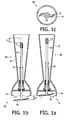
- Figures 1a,b,c show a first embodiment of a blender arm 10 according to the present invention, Figures 1a and 1b as cut in axial direction and Figure 1c from below.
- the main components are a tubular body 12 including a rotary shaft 13.
- the tubular body 12 is enlarged to form a cage 14 as peripheral protection around the blade 15, fixed at the lower end of the rotary shaft 13.
- the upper end of the rotary shaft 13 shows a connection 11 to connect the rotary shaft 13 to a power unit (not shown) to induce it into rotation to operate the blade 15.
- the rotating blade 15 then chops or purees or mixes what is surrounding it.
- the rotary shaft 13 is held inside the tubular body 12, so that it can be moved in axial direction by pushing, e.g. with the finger onto the connection 11, so that the blade 15 moves over a length L1 from a retracted position R inside the cage 14 ( Figure 1a ) to a protracted position P1 outside the cage 14 ( Figure 1b ).
- position P1 allows to easily wash the lower part of the blender arm 10 even behind the blade 15 to thoroughly remove any residues, as well as the lower end of the rotary shaft 13.
- an automatic movement back to the retracted position R may be achieved by more complex means as well, e.g. by using a motor.
- FIGs 2a,b show another embodiment of the blender arm 10 according to the present invention.
- the pneumatic resilient element has been replaced by a metal spring 26 that is expanded, when the blade 15 is in the retracted position R, and compressed, when the blade 15 is in the protracted position P1.
- the blade 15 is fixed to the blade shaft 16, which in turn is releasably attached to the rotary shaft 13.
- the blender arm 10 of Figures 2a,b gives the possibility of removing the blade 15 with blade shaft 16 for sharpening or exchanging it with a new one, when the blade 15 is in position P1.
- FIGS 4a,b show embodiments of the blender arm 10 according to the present invention with various safety switches 30, 40, 50 that make sure that the blade 15 is not operated in the protracted position P1, which could be dangerous and a nuisance if the food to be processed is splashed around. These possibilities are to be taken as examples only. Any kind of appropriate safety switch known in the art can be used as well.
- connection 11 cooperates with a mechanical switch 31 in the motor block connection 61 inside the housing 62 of a power unit part of a food processor. If the connection 11 is inserted into the motor block connection 61, it presses onto the mechanical switch 61 and thus allows the motor block to be powered, in case the general switch of the food processor is switched on.
- the safety switch 40 is based on a magnetic approach.
- the connection 41 is made of magnetic material.
- the magnetic switch 42 on the inner side of the tubular body 12 measures the magnetic field (broken line) of the magnetic connection 41. If a certain magnetic field is reached, because the magnetic connector 11 is near enough to the magnetic switch 42, i.e. the blade 15 in a retracted position R, a corresponding signal is transmitted to some power control of the food processor allowing the motor block to be powered, if desired.
- the safety switch 50 is an optical one. There is a mark 53 on the rotary shaft 13 indicating the blade 15 which is in the retracted position R By means of a light emitter 51 (light symbolized by broken line), e.g. a light emitting diode, and a detector 52, e.g. a photo diode, it can be detected whether the right position is reached or not, and corresponding signals are sent to some power control of the food processor.
- a light emitter 51 light symbolized by broken line
- a detector 52 e.g. a photo diode
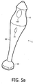
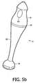
- FIGS 5a to 5d show different embodiments of a hand blender 1 with a blender arm 10 according to the present invention.
- various actuating elements are provided.
- the actuating elements are connected to the rotary shaft inside the tubular body by conventional means, e.g. mechanical means, to translate the movement of the actuating element into an appropriate movement of the rotary shaft in axial direction.
- the blender arm 10 is attached to a power unit part 6 of the hand blender 1.
- the hand blender 1 is switched on and off by means of the switch 63.
- the embodiment of Figure 5 a has a button 21 that has to be pushed and held to get the blade into a protracted position and stay in it during cleaning. If the button 21 is released, the blade moves automatically back to a retracted position due to a resilient element, as explained before. It will be noted that in view of the cage 14 having openings, it could be enough to move the blade, for safety reasons, only up to the height of the openings of the cage for cleaning, but it would be more complicated to reach the same cleaning result as with a blade outside the cage 14.
- FIG. 5b shows a ring 24 instead of the button 21.
- the ring has to be turned to move the rotary shaft with the blade.
- the embodiment of Figure 5c has a button 22 to be pushed along the guidance 23.
- the button 22 can be pushed into two different positions in which it can be locked by pushing it to the side against an edge 25, e.g. against the resilient force of any resilient element.
- the different positions of the button 22 are equivalent to different positions of the blade.
- the actual position is the most retracted one. If the user so desires, it is not necessary to push the button up to a locking position, but can stop anywhere in-between, if that is enough to thoroughly clean the tool or remove the tool. But if there is a resilient element forcing the rotary shaft and the tool back to the most retracted position, the user should hold the button 22 in that position until he is done.
- Figure 5d shows an embodiment similar to the embodiment of Figure 5c , but with only one locking position.
- the present invention may be applied to any other food processor than a hand blender, for example a hand mixer 2 with blender arm 10, wherein the hand mixer 2 contains the motor part 6 for driving the blender arm 10.
Landscapes
- Engineering & Computer Science (AREA)
- Mechanical Engineering (AREA)
- Food Science & Technology (AREA)
- Food-Manufacturing Devices (AREA)
- Disintegrating Or Milling (AREA)
Claims (11)
- Robot de cuisine (1, 2) avec une unité de puissance (6) et un bras mélangeur, le bras mélangeur ayant un corps tubulaire qui est équipé, à une extrémité, d'une connexion pour la connexion par rapport à une unité de puissance, y compris un arbre axialement rotatif avec un outil à l'extrémité qui est opposée à l'extrémité de connexion, outil autour duquel une protection périphérique est établie, l'arbre rotatif (13) avec l'outil (15) étant fixé d'une manière mobile dans la direction axiale au corps tubulaire (12), de sorte que l'outil (15) peut être positionné dans une position retirée (R) ou dans une position prolongée (P1, P2), caractérisé en ce qu'il comprend encore un dispositif de commutation de sécurité (30, 40, 50) pour commander la position de l'outil et en ce qu'il permet le fonctionnement dans le cas où l'outil (15) est positionné dans une position retirée (R).
- Robot de cuisine selon la revendication 1, dans lequel l'unité de puissance présente une connexion d'unité de puissance (61) qui coopère, en fonctionnement, avec une connexion de bras mélangeur (11) et qui présente un commutateur (30) étant actionné par la connexion de bras mélangeur (11) alors que le bras mélangeur (10) est monté sur l'unité de puissance (6) avec l'outil (15) dans sa position retirée (R).
- Bras mélangeur (10) pour être utilisé dans le robot de cuisine (1, 2) selon la revendication 1 ou selon la revendication 2, ayant un corps tubulaire qui est équipé, à une extrémité, d'une connexion pour la connexion d'une unité de puissance, y compris un arbre axialement rotatif avec un outil à l'extrémité qui est opposée à l'extrémité de connexion, outil autour duquel une protection périphérique est établie, dans lequel l'arbre rotatif (13) avec l'outil (15) est fixé d'une manière mobile dans la direction axiale au corps tubulaire (12), de sorte que l'outil (15) peut être positionné dans une position retirée (R) ou dans une position prolongée (P1, P2), caractérisé en ce que le bras mélangeur (10) comprend un commutateur de sécurité (40, 50) pour détecter l'outil (15) dans sa position retirée (R) et pour transmettre un signal correspondant à une unité de commande de puissance du robot de cuisine (1, 2).
- Bras mélangeur selon la revendication 3, caractérisé en ce que l'arbre rotatif (13) est fonctionnellement relié à un élément d'actionnement (21, 22, 23, 24) qui est conçu en tant que partie du corps tubulaire (12) et qui déplace l'arbre rotatif (13) dans la direction axiale à partir de la position retirée (R) à la position prolongée (P1, P2) de l'outil (15).
- Bras mélangeur selon la revendication 3 ou selon la revendication 4, caractérisé en ce que l'arbre rotatif (13) avec l'outil (15) est fixé d'une manière mobile dans la direction axiale au corps tubulaire (12), de sorte que l'outil (15) retourne automatiquement à partir de la position prolongée (P1, P2) à la position (R).
- Bras mélangeur selon l'une quelconque des revendications précédentes 3 à 5, caractérisé en ce qu'il comprend encore un élément résilient (26, 27) qui est fonctionnellement relié au corps tubulaire (12) et à l'arbre rotatif (13) de manière à déplacer l'arbre rotatif (13) à partir de la position prolongée (P1, P2) à la position retirée (R) de l'outil (15).
- Bras mélangeur selon l'une quelconque des revendications précédentes 3 à 6, caractérisé en ce qu'il comprend encore un dispositif de verrouillage (25) qui verrouille l'outil (15) dans la position prolongée (P1, P2).
- Bras mélangeur selon l'une quelconque des revendications précédentes 3 à 7, caractérisé en ce que l'outil (15) est fixé d'une manière susceptible de dégagement à l'arbre rotatif (13), dans lequel le dégagement est possible dans la position prolongée (P1, P2).
- Bras mélangeur selon l'une quelconque des revendications précédentes 3 à 8, caractérisé en ce que l'outil (15) est fixé d'une manière susceptible de dégagement à l'arbre rotatif (13) et peut être positionné dans une deuxième position prolongée (P2) afin d'être dégagé.
- Bras mélangeur selon l'une quelconque des revendications précédentes 3 à 9, caractérisé en ce que le commutateur de sécurité (40) est un commutateur magnétique (42).
- Bras mélangeur selon l'une quelconque des revendications précédentes 3 à 10, caractérisé en ce que le commutateur de sécurité (50) est un commutateur optique ayant un émetteur de lumière (51) et un détecteur de lumière (52).
Priority Applications (1)
| Application Number | Priority Date | Filing Date | Title |
|---|---|---|---|
| EP06765716A EP1903921B1 (fr) | 2005-06-10 | 2006-06-02 | Bras melangeur et robot de cuisine |
Applications Claiming Priority (3)
| Application Number | Priority Date | Filing Date | Title |
|---|---|---|---|
| EP05105117 | 2005-06-10 | ||
| PCT/IB2006/051775 WO2006131868A2 (fr) | 2005-06-10 | 2006-06-02 | Bras melangeur et robot de cuisine |
| EP06765716A EP1903921B1 (fr) | 2005-06-10 | 2006-06-02 | Bras melangeur et robot de cuisine |
Publications (2)
| Publication Number | Publication Date |
|---|---|
| EP1903921A2 EP1903921A2 (fr) | 2008-04-02 |
| EP1903921B1 true EP1903921B1 (fr) | 2009-10-07 |
Family
ID=37309510
Family Applications (1)
| Application Number | Title | Priority Date | Filing Date |
|---|---|---|---|
| EP06765716A Not-in-force EP1903921B1 (fr) | 2005-06-10 | 2006-06-02 | Bras melangeur et robot de cuisine |
Country Status (7)
| Country | Link |
|---|---|
| US (2) | US8038338B2 (fr) |
| EP (1) | EP1903921B1 (fr) |
| JP (1) | JP5139272B2 (fr) |
| CN (1) | CN101193581B (fr) |
| AT (1) | ATE444695T1 (fr) |
| DE (1) | DE602006009659D1 (fr) |
| WO (1) | WO2006131868A2 (fr) |
Families Citing this family (23)
| Publication number | Priority date | Publication date | Assignee | Title |
|---|---|---|---|---|
| EP1903921B1 (fr) * | 2005-06-10 | 2009-10-07 | Koninklijke Philips Electronics N.V. | Bras melangeur et robot de cuisine |
| DE102005038917A1 (de) * | 2005-08-17 | 2007-02-22 | BSH Bosch und Siemens Hausgeräte GmbH | Stabmixer mit durch einen Spanndeckel verbundenen Gehäuseschalen |
| ES2341821B1 (es) * | 2007-04-19 | 2011-04-08 | Electrodomesticos Taurus, S.L. | Util de corte y cabezal de trabajo para batidora electrica de varilla. |
| DE102011077343A1 (de) * | 2010-06-10 | 2011-12-15 | BSH Bosch und Siemens Hausgeräte GmbH | Handküchengerät mit Schutzabdeckung |
| USD668911S1 (en) * | 2010-09-10 | 2012-10-16 | Braun Gmbh | Hand blender |
| AU348039S (en) * | 2012-08-30 | 2013-04-12 | Koninl Philips Electronics Nv | Blender bar |
| USD727096S1 (en) * | 2013-09-06 | 2015-04-21 | De'longhi Braun Household Gmbh | Hand blender base |
| CN103705072B (zh) * | 2013-12-28 | 2016-08-17 | 宁波市镇海区龙赛中学 | 一种自动搅拌杯 |
| AU2015221415B2 (en) * | 2014-02-19 | 2019-05-16 | Breville Pty Limited | Hand mixer |
| USD763035S1 (en) * | 2015-01-21 | 2016-08-09 | True Fabrications, Inc. | Bar tool |
| DE102015207196B3 (de) * | 2015-04-21 | 2016-05-25 | De'longhi Braun Household Gmbh | Arbeitsgerät mit teleskopartig beweglichem Schaft zum Rühren oder Zerkleinern von Nahrungsmitteln |
| DE102015207197B3 (de) * | 2015-04-21 | 2016-06-16 | De'longhi Braun Household Gmbh | Stabmixermesser mit Fräskante |
| DE102015008482A1 (de) * | 2015-07-01 | 2017-02-16 | Ika-Werke Gmbh & Co. Kg | Dispergierwerkzeug, Dispergiervorrichtung und Dispergieranordnung |
| FR3048599B1 (fr) * | 2016-03-11 | 2018-04-13 | Seb S.A. | Pied de mixage comprenant un arbre d'entrainement destine a etre entraine en rotation par un boitier moteur |
| US10940089B2 (en) * | 2017-05-17 | 2021-03-09 | Ghanem Abusbeih | Medication crushing, grinding, and administering syringe and method of use |
| KR102589599B1 (ko) * | 2017-07-18 | 2023-10-16 | 블릭스 리미티드 | 식품 준비 용기 어셈블리, 시스템 및 방법 |
| DE102017213778B4 (de) * | 2017-08-08 | 2019-10-10 | De'longhi Braun Household Gmbh | Arbeitsgerät zum Rühren oder Zerkleinern von Nahrungsmitteln |
| CN107456120B (zh) * | 2017-08-15 | 2019-11-22 | 珠海格力电器股份有限公司 | 料理机刀具组件及包括其的料理机 |
| CN108013729B (zh) * | 2017-12-29 | 2020-07-24 | 佛山市顺德区三的电器制造有限公司 | 一种家用榨汁机 |
| CN108324133B (zh) * | 2018-04-18 | 2020-03-06 | 台州正铭智能家居科技有限公司 | 一种绞菜器 |
| CN109645851A (zh) * | 2018-12-11 | 2019-04-19 | 孙磊 | 一种防护榨汁机 |
| DE102019206029B4 (de) * | 2019-04-26 | 2022-02-10 | De'longhi Braun Household Gmbh | Küchengerät und Zubehörelement zum Abdichten einer Schutzhaube eines Küchengeräts |
| ES2915696B2 (es) * | 2020-12-23 | 2023-05-31 | Cecotec Res And Development S L | Batidora de mano con sistema amortiguado para accesorios |
Family Cites Families (17)
| Publication number | Priority date | Publication date | Assignee | Title |
|---|---|---|---|---|
| LU35534A1 (fr) * | ||||
| DE1224007B (de) * | 1964-01-16 | 1966-09-01 | Electrostar G M B H | Zerkleinerungswerkzeug mit Antriebswelle, die an eine untersetzt angetriebene Welle einer von Hand tragbaren elektromotorischen Kuechenmaschine ankuppelbar ist |
| JPS4811156U (fr) * | 1971-06-18 | 1973-02-07 | ||
| JPS6029950Y2 (ja) * | 1981-01-12 | 1985-09-09 | 松下電器産業株式会社 | 調理器 |
| FR2515021B1 (fr) * | 1981-10-28 | 1986-04-18 | Moulinex Sa | Mixeur menager |
| DE19504638A1 (de) * | 1995-02-13 | 1996-08-14 | Braun Ag | Verfahren für ein Arbeitsgerät, insbesondere Stabmixer, zum Rühren oder Zerkleinern von Nahrungsmitteln in einem Behälter |
| US5863118A (en) * | 1997-07-29 | 1999-01-26 | Conair Corporation | Blender with extendible housing |
| DE19750183A1 (de) | 1997-11-13 | 1999-05-27 | Wepamat Maschinenbau Gmbh | Verfahren und Vorrichtung zur Banderolierung einer Ware mit Etiketten |
| DE19750813C2 (de) | 1997-11-17 | 2002-06-13 | Braun Gmbh | Arbeitsgerät zum Rühren oder Zerkleinern von Nahrungsmitteln, insbesondere Stabmixer |
| FR2780264B1 (fr) | 1998-06-29 | 2000-09-08 | Dito Sama | Outil de machine de traitement de produits notamment alimentaires |
| ES2182707B2 (es) | 2001-07-03 | 2004-02-01 | Irimartek S A | Brazo triturador con el extremo desmontable para limpieza |
| NZ518432A (en) * | 2002-04-16 | 2004-09-24 | Agres Ltd | A homogeniser and method of cleaning same. |
| DE10244602A1 (de) | 2002-09-25 | 2004-04-15 | BSH Bosch und Siemens Hausgeräte GmbH | Kupplungsvorrichtung für Küchengeräte |
| US6974244B1 (en) * | 2002-11-15 | 2005-12-13 | King-Yuan Lin | Hand-held wand mixer |
| FR2854561B1 (fr) * | 2003-05-09 | 2006-06-02 | Dito Sama | Outil de machine de traitement de produits alimentaires ayant des moyens de verrouillage ameliores, et machine equipee d'un tel outil |
| FR2860698B1 (fr) * | 2003-10-14 | 2005-12-09 | Seb Sa | Pied de mixage et mixeur menager de type plongeant muni d'un tel pied de mixage. |
| EP1903921B1 (fr) * | 2005-06-10 | 2009-10-07 | Koninklijke Philips Electronics N.V. | Bras melangeur et robot de cuisine |
-
2006
- 2006-06-02 EP EP06765716A patent/EP1903921B1/fr not_active Not-in-force
- 2006-06-02 AT AT06765716T patent/ATE444695T1/de not_active IP Right Cessation
- 2006-06-02 US US11/917,121 patent/US8038338B2/en not_active Expired - Fee Related
- 2006-06-02 DE DE602006009659T patent/DE602006009659D1/de active Active
- 2006-06-02 CN CN200680020354.6A patent/CN101193581B/zh not_active Expired - Fee Related
- 2006-06-02 WO PCT/IB2006/051775 patent/WO2006131868A2/fr not_active Ceased
- 2006-06-02 JP JP2008515349A patent/JP5139272B2/ja not_active Expired - Fee Related
-
2011
- 2011-09-30 US US13/249,307 patent/US8454223B2/en not_active Expired - Fee Related
Also Published As
| Publication number | Publication date |
|---|---|
| JP5139272B2 (ja) | 2013-02-06 |
| CN101193581A (zh) | 2008-06-04 |
| US8454223B2 (en) | 2013-06-04 |
| US20080198693A1 (en) | 2008-08-21 |
| WO2006131868A2 (fr) | 2006-12-14 |
| WO2006131868A3 (fr) | 2007-02-22 |
| JP2008541981A (ja) | 2008-11-27 |
| EP1903921A2 (fr) | 2008-04-02 |
| US20120018552A1 (en) | 2012-01-26 |
| US8038338B2 (en) | 2011-10-18 |
| DE602006009659D1 (de) | 2009-11-19 |
| CN101193581B (zh) | 2010-11-10 |
| ATE444695T1 (de) | 2009-10-15 |
Similar Documents
| Publication | Publication Date | Title |
|---|---|---|
| US8454223B2 (en) | Blender arm and food processor | |
| US20080217446A1 (en) | Safety actuator for a food processor having a visual indication | |
| US5316382A (en) | Electrically driven hand mixer with knife-like tool interlock | |
| US11963638B2 (en) | Domestic appliance for processing foods and splash guard therefor | |
| US20140299701A1 (en) | Food processor having integrated spaatula | |
| EP1420676B1 (fr) | Robot menager comprenant differents outils | |
| RU2578585C2 (ru) | Инструмент для приводимого двигателем кухонного прибора | |
| CN107752805B (zh) | 手持搅拌器 | |
| DK146646B (da) | Husholdningsmaskine til soenderdeling af levnedsmidler, navnlig af koed eller loeg | |
| RU2453259C2 (ru) | Предохранительный механизм для кухонного комбайна с двумя участками сочленения | |
| CN106136960B (zh) | 食品加工机用刀具 | |
| JP5522838B2 (ja) | 電動調理器 | |
| ES2764133T3 (es) | Accesorio de procesamiento con medio de sujeción y herramienta de procesamiento | |
| EP3427619B1 (fr) | Moyen de détachement d'outil pour des appareils de cuisine | |
| EP2269495A1 (fr) | Procédé de fonctionnement d'un appareil domestique et appareil domestique | |
| US9010990B2 (en) | Shaft-actuated spindle mixer | |
| CN116491826B (zh) | 研磨机 | |
| UA128902C2 (uk) | Моторний блок електропобутового приладу, що виконаний з можливістю утримання рукою | |
| EP2878246B1 (fr) | Mécanisme d'éjection d'outil pour appareils domestiques | |
| RU2815109C2 (ru) | Моторный блок электробытового прибора, выполненный с возможностью удержания рукой | |
| JP6520355B2 (ja) | 電動回転調理器 | |
| CN107569134A (zh) | 料理机 | |
| CN117320601A (zh) | 用于食品料理机的食品料理机结构和切碎组件 | |
| KR20010000711U (ko) | 전기믹서기와 그 안전장치 | |
| KR100228201B1 (ko) | 주서/믹서의 회전식 스위치 |
Legal Events
| Date | Code | Title | Description |
|---|---|---|---|
| PUAI | Public reference made under article 153(3) epc to a published international application that has entered the european phase |
Free format text: ORIGINAL CODE: 0009012 |
|
| 17P | Request for examination filed |
Effective date: 20080110 |
|
| AK | Designated contracting states |
Kind code of ref document: A2 Designated state(s): AT BE BG CH CY CZ DE DK EE ES FI FR GB GR HU IE IS IT LI LT LU LV MC NL PL PT RO SE SI SK TR |
|
| 17Q | First examination report despatched |
Effective date: 20080513 |
|
| DAX | Request for extension of the european patent (deleted) | ||
| GRAP | Despatch of communication of intention to grant a patent |
Free format text: ORIGINAL CODE: EPIDOSNIGR1 |
|
| GRAS | Grant fee paid |
Free format text: ORIGINAL CODE: EPIDOSNIGR3 |
|
| GRAA | (expected) grant |
Free format text: ORIGINAL CODE: 0009210 |
|
| AK | Designated contracting states |
Kind code of ref document: B1 Designated state(s): AT BE BG CH CY CZ DE DK EE ES FI FR GB GR HU IE IS IT LI LT LU LV MC NL PL PT RO SE SI SK TR |
|
| REG | Reference to a national code |
Ref country code: GB Ref legal event code: FG4D |
|
| REG | Reference to a national code |
Ref country code: CH Ref legal event code: EP |
|
| REG | Reference to a national code |
Ref country code: IE Ref legal event code: FG4D |
|
| REF | Corresponds to: |
Ref document number: 602006009659 Country of ref document: DE Date of ref document: 20091119 Kind code of ref document: P |
|
| PG25 | Lapsed in a contracting state [announced via postgrant information from national office to epo] |
Ref country code: SI Free format text: LAPSE BECAUSE OF FAILURE TO SUBMIT A TRANSLATION OF THE DESCRIPTION OR TO PAY THE FEE WITHIN THE PRESCRIBED TIME-LIMIT Effective date: 20091007 |
|
| NLV1 | Nl: lapsed or annulled due to failure to fulfill the requirements of art. 29p and 29m of the patents act | ||
| LTIE | Lt: invalidation of european patent or patent extension |
Effective date: 20091007 |
|
| PG25 | Lapsed in a contracting state [announced via postgrant information from national office to epo] |
Ref country code: PT Free format text: LAPSE BECAUSE OF FAILURE TO SUBMIT A TRANSLATION OF THE DESCRIPTION OR TO PAY THE FEE WITHIN THE PRESCRIBED TIME-LIMIT Effective date: 20100208 Ref country code: FI Free format text: LAPSE BECAUSE OF FAILURE TO SUBMIT A TRANSLATION OF THE DESCRIPTION OR TO PAY THE FEE WITHIN THE PRESCRIBED TIME-LIMIT Effective date: 20091007 Ref country code: LT Free format text: LAPSE BECAUSE OF FAILURE TO SUBMIT A TRANSLATION OF THE DESCRIPTION OR TO PAY THE FEE WITHIN THE PRESCRIBED TIME-LIMIT Effective date: 20091007 Ref country code: ES Free format text: LAPSE BECAUSE OF FAILURE TO SUBMIT A TRANSLATION OF THE DESCRIPTION OR TO PAY THE FEE WITHIN THE PRESCRIBED TIME-LIMIT Effective date: 20100118 Ref country code: SE Free format text: LAPSE BECAUSE OF FAILURE TO SUBMIT A TRANSLATION OF THE DESCRIPTION OR TO PAY THE FEE WITHIN THE PRESCRIBED TIME-LIMIT Effective date: 20091007 Ref country code: IS Free format text: LAPSE BECAUSE OF FAILURE TO SUBMIT A TRANSLATION OF THE DESCRIPTION OR TO PAY THE FEE WITHIN THE PRESCRIBED TIME-LIMIT Effective date: 20100207 |
|
| PG25 | Lapsed in a contracting state [announced via postgrant information from national office to epo] |
Ref country code: PL Free format text: LAPSE BECAUSE OF FAILURE TO SUBMIT A TRANSLATION OF THE DESCRIPTION OR TO PAY THE FEE WITHIN THE PRESCRIBED TIME-LIMIT Effective date: 20091007 Ref country code: LV Free format text: LAPSE BECAUSE OF FAILURE TO SUBMIT A TRANSLATION OF THE DESCRIPTION OR TO PAY THE FEE WITHIN THE PRESCRIBED TIME-LIMIT Effective date: 20091007 |
|
| PG25 | Lapsed in a contracting state [announced via postgrant information from national office to epo] |
Ref country code: AT Free format text: LAPSE BECAUSE OF FAILURE TO SUBMIT A TRANSLATION OF THE DESCRIPTION OR TO PAY THE FEE WITHIN THE PRESCRIBED TIME-LIMIT Effective date: 20091007 Ref country code: BE Free format text: LAPSE BECAUSE OF FAILURE TO SUBMIT A TRANSLATION OF THE DESCRIPTION OR TO PAY THE FEE WITHIN THE PRESCRIBED TIME-LIMIT Effective date: 20091007 |
|
| PG25 | Lapsed in a contracting state [announced via postgrant information from national office to epo] |
Ref country code: NL Free format text: LAPSE BECAUSE OF FAILURE TO SUBMIT A TRANSLATION OF THE DESCRIPTION OR TO PAY THE FEE WITHIN THE PRESCRIBED TIME-LIMIT Effective date: 20091007 Ref country code: EE Free format text: LAPSE BECAUSE OF FAILURE TO SUBMIT A TRANSLATION OF THE DESCRIPTION OR TO PAY THE FEE WITHIN THE PRESCRIBED TIME-LIMIT Effective date: 20091007 Ref country code: RO Free format text: LAPSE BECAUSE OF FAILURE TO SUBMIT A TRANSLATION OF THE DESCRIPTION OR TO PAY THE FEE WITHIN THE PRESCRIBED TIME-LIMIT Effective date: 20091007 Ref country code: BG Free format text: LAPSE BECAUSE OF FAILURE TO SUBMIT A TRANSLATION OF THE DESCRIPTION OR TO PAY THE FEE WITHIN THE PRESCRIBED TIME-LIMIT Effective date: 20100107 Ref country code: DK Free format text: LAPSE BECAUSE OF FAILURE TO SUBMIT A TRANSLATION OF THE DESCRIPTION OR TO PAY THE FEE WITHIN THE PRESCRIBED TIME-LIMIT Effective date: 20091007 |
|
| PLBE | No opposition filed within time limit |
Free format text: ORIGINAL CODE: 0009261 |
|
| STAA | Information on the status of an ep patent application or granted ep patent |
Free format text: STATUS: NO OPPOSITION FILED WITHIN TIME LIMIT |
|
| PG25 | Lapsed in a contracting state [announced via postgrant information from national office to epo] |
Ref country code: SK Free format text: LAPSE BECAUSE OF FAILURE TO SUBMIT A TRANSLATION OF THE DESCRIPTION OR TO PAY THE FEE WITHIN THE PRESCRIBED TIME-LIMIT Effective date: 20091007 Ref country code: CZ Free format text: LAPSE BECAUSE OF FAILURE TO SUBMIT A TRANSLATION OF THE DESCRIPTION OR TO PAY THE FEE WITHIN THE PRESCRIBED TIME-LIMIT Effective date: 20091007 |
|
| 26N | No opposition filed |
Effective date: 20100708 |
|
| PG25 | Lapsed in a contracting state [announced via postgrant information from national office to epo] |
Ref country code: GR Free format text: LAPSE BECAUSE OF FAILURE TO SUBMIT A TRANSLATION OF THE DESCRIPTION OR TO PAY THE FEE WITHIN THE PRESCRIBED TIME-LIMIT Effective date: 20100108 |
|
| PG25 | Lapsed in a contracting state [announced via postgrant information from national office to epo] |
Ref country code: MC Free format text: LAPSE BECAUSE OF NON-PAYMENT OF DUE FEES Effective date: 20100630 |
|
| REG | Reference to a national code |
Ref country code: CH Ref legal event code: PL |
|
| PG25 | Lapsed in a contracting state [announced via postgrant information from national office to epo] |
Ref country code: IT Free format text: LAPSE BECAUSE OF FAILURE TO SUBMIT A TRANSLATION OF THE DESCRIPTION OR TO PAY THE FEE WITHIN THE PRESCRIBED TIME-LIMIT Effective date: 20091007 |
|
| PG25 | Lapsed in a contracting state [announced via postgrant information from national office to epo] |
Ref country code: IE Free format text: LAPSE BECAUSE OF NON-PAYMENT OF DUE FEES Effective date: 20100602 Ref country code: CH Free format text: LAPSE BECAUSE OF NON-PAYMENT OF DUE FEES Effective date: 20100630 Ref country code: LI Free format text: LAPSE BECAUSE OF NON-PAYMENT OF DUE FEES Effective date: 20100630 |
|
| PG25 | Lapsed in a contracting state [announced via postgrant information from national office to epo] |
Ref country code: CY Free format text: LAPSE BECAUSE OF FAILURE TO SUBMIT A TRANSLATION OF THE DESCRIPTION OR TO PAY THE FEE WITHIN THE PRESCRIBED TIME-LIMIT Effective date: 20091007 |
|
| PG25 | Lapsed in a contracting state [announced via postgrant information from national office to epo] |
Ref country code: HU Free format text: LAPSE BECAUSE OF FAILURE TO SUBMIT A TRANSLATION OF THE DESCRIPTION OR TO PAY THE FEE WITHIN THE PRESCRIBED TIME-LIMIT Effective date: 20100408 Ref country code: LU Free format text: LAPSE BECAUSE OF NON-PAYMENT OF DUE FEES Effective date: 20100602 |
|
| PG25 | Lapsed in a contracting state [announced via postgrant information from national office to epo] |
Ref country code: TR Free format text: LAPSE BECAUSE OF FAILURE TO SUBMIT A TRANSLATION OF THE DESCRIPTION OR TO PAY THE FEE WITHIN THE PRESCRIBED TIME-LIMIT Effective date: 20091007 |
|
| REG | Reference to a national code |
Ref country code: DE Ref legal event code: R082 Ref document number: 602006009659 Country of ref document: DE Representative=s name: MEISSNER, BOLTE & PARTNER GBR, DE |
|
| REG | Reference to a national code |
Ref country code: DE Ref legal event code: R082 Ref document number: 602006009659 Country of ref document: DE Representative=s name: MEISSNER BOLTE PATENTANWAELTE RECHTSANWAELTE P, DE Effective date: 20140328 Ref country code: DE Ref legal event code: R082 Ref document number: 602006009659 Country of ref document: DE Representative=s name: MEISSNER, BOLTE & PARTNER GBR, DE Effective date: 20140328 Ref country code: DE Ref legal event code: R081 Ref document number: 602006009659 Country of ref document: DE Owner name: KONINKLIJKE PHILIPS N.V., NL Free format text: FORMER OWNER: KONINKLIJKE PHILIPS ELECTRONICS N.V., EINDHOVEN, NL Effective date: 20140328 |
|
| REG | Reference to a national code |
Ref country code: FR Ref legal event code: CA Effective date: 20141126 Ref country code: FR Ref legal event code: CD Owner name: KONINKLIJKE PHILIPS ELECTRONICS N.V., NL Effective date: 20141126 |
|
| REG | Reference to a national code |
Ref country code: FR Ref legal event code: PLFP Year of fee payment: 11 |
|
| REG | Reference to a national code |
Ref country code: FR Ref legal event code: PLFP Year of fee payment: 12 |
|
| PGFP | Annual fee paid to national office [announced via postgrant information from national office to epo] |
Ref country code: FR Payment date: 20170629 Year of fee payment: 12 Ref country code: GB Payment date: 20170630 Year of fee payment: 12 |
|
| PGFP | Annual fee paid to national office [announced via postgrant information from national office to epo] |
Ref country code: DE Payment date: 20170831 Year of fee payment: 12 |
|
| REG | Reference to a national code |
Ref country code: DE Ref legal event code: R119 Ref document number: 602006009659 Country of ref document: DE |
|
| GBPC | Gb: european patent ceased through non-payment of renewal fee |
Effective date: 20180602 |
|
| PG25 | Lapsed in a contracting state [announced via postgrant information from national office to epo] |
Ref country code: FR Free format text: LAPSE BECAUSE OF NON-PAYMENT OF DUE FEES Effective date: 20180630 Ref country code: GB Free format text: LAPSE BECAUSE OF NON-PAYMENT OF DUE FEES Effective date: 20180602 Ref country code: DE Free format text: LAPSE BECAUSE OF NON-PAYMENT OF DUE FEES Effective date: 20190101 |