EP1903983B1 - Crimping- und kantenschutzelemente - Google Patents
Crimping- und kantenschutzelemente Download PDFInfo
- Publication number
- EP1903983B1 EP1903983B1 EP06737773A EP06737773A EP1903983B1 EP 1903983 B1 EP1903983 B1 EP 1903983B1 EP 06737773 A EP06737773 A EP 06737773A EP 06737773 A EP06737773 A EP 06737773A EP 1903983 B1 EP1903983 B1 EP 1903983B1
- Authority
- EP
- European Patent Office
- Prior art keywords
- region
- stent
- length
- balloon
- chamber
- Prior art date
- Legal status (The legal status is an assumption and is not a legal conclusion. Google has not performed a legal analysis and makes no representation as to the accuracy of the status listed.)
- Expired - Lifetime
Links
Images



Classifications
-
- A—HUMAN NECESSITIES
- A61—MEDICAL OR VETERINARY SCIENCE; HYGIENE
- A61F—FILTERS IMPLANTABLE INTO BLOOD VESSELS; PROSTHESES; DEVICES PROVIDING PATENCY TO, OR PREVENTING COLLAPSING OF, TUBULAR STRUCTURES OF THE BODY, e.g. STENTS; ORTHOPAEDIC, NURSING OR CONTRACEPTIVE DEVICES; FOMENTATION; TREATMENT OR PROTECTION OF EYES OR EARS; BANDAGES, DRESSINGS OR ABSORBENT PADS; FIRST-AID KITS
- A61F2/00—Filters implantable into blood vessels; Prostheses, i.e. artificial substitutes or replacements for parts of the body; Appliances for connecting them with the body; Devices providing patency to, or preventing collapsing of, tubular structures of the body, e.g. stents
- A61F2/95—Instruments specially adapted for placement or removal of stents or stent-grafts
- A61F2/958—Inflatable balloons for placing stents or stent-grafts
-
- A—HUMAN NECESSITIES
- A61—MEDICAL OR VETERINARY SCIENCE; HYGIENE
- A61F—FILTERS IMPLANTABLE INTO BLOOD VESSELS; PROSTHESES; DEVICES PROVIDING PATENCY TO, OR PREVENTING COLLAPSING OF, TUBULAR STRUCTURES OF THE BODY, e.g. STENTS; ORTHOPAEDIC, NURSING OR CONTRACEPTIVE DEVICES; FOMENTATION; TREATMENT OR PROTECTION OF EYES OR EARS; BANDAGES, DRESSINGS OR ABSORBENT PADS; FIRST-AID KITS
- A61F2/00—Filters implantable into blood vessels; Prostheses, i.e. artificial substitutes or replacements for parts of the body; Appliances for connecting them with the body; Devices providing patency to, or preventing collapsing of, tubular structures of the body, e.g. stents
- A61F2/95—Instruments specially adapted for placement or removal of stents or stent-grafts
- A61F2/9522—Means for mounting a stent or stent-graft onto or into a placement instrument
-
- A—HUMAN NECESSITIES
- A61—MEDICAL OR VETERINARY SCIENCE; HYGIENE
- A61F—FILTERS IMPLANTABLE INTO BLOOD VESSELS; PROSTHESES; DEVICES PROVIDING PATENCY TO, OR PREVENTING COLLAPSING OF, TUBULAR STRUCTURES OF THE BODY, e.g. STENTS; ORTHOPAEDIC, NURSING OR CONTRACEPTIVE DEVICES; FOMENTATION; TREATMENT OR PROTECTION OF EYES OR EARS; BANDAGES, DRESSINGS OR ABSORBENT PADS; FIRST-AID KITS
- A61F2/00—Filters implantable into blood vessels; Prostheses, i.e. artificial substitutes or replacements for parts of the body; Appliances for connecting them with the body; Devices providing patency to, or preventing collapsing of, tubular structures of the body, e.g. stents
- A61F2/95—Instruments specially adapted for placement or removal of stents or stent-grafts
- A61F2/9522—Means for mounting a stent or stent-graft onto or into a placement instrument
- A61F2/9524—Iris-type crimpers
-
- Y—GENERAL TAGGING OF NEW TECHNOLOGICAL DEVELOPMENTS; GENERAL TAGGING OF CROSS-SECTIONAL TECHNOLOGIES SPANNING OVER SEVERAL SECTIONS OF THE IPC; TECHNICAL SUBJECTS COVERED BY FORMER USPC CROSS-REFERENCE ART COLLECTIONS [XRACs] AND DIGESTS
- Y10—TECHNICAL SUBJECTS COVERED BY FORMER USPC
- Y10T—TECHNICAL SUBJECTS COVERED BY FORMER US CLASSIFICATION
- Y10T29/00—Metal working
- Y10T29/49—Method of mechanical manufacture
- Y10T29/49826—Assembling or joining
- Y10T29/49908—Joining by deforming
-
- Y—GENERAL TAGGING OF NEW TECHNOLOGICAL DEVELOPMENTS; GENERAL TAGGING OF CROSS-SECTIONAL TECHNOLOGIES SPANNING OVER SEVERAL SECTIONS OF THE IPC; TECHNICAL SUBJECTS COVERED BY FORMER USPC CROSS-REFERENCE ART COLLECTIONS [XRACs] AND DIGESTS
- Y10—TECHNICAL SUBJECTS COVERED BY FORMER USPC
- Y10T—TECHNICAL SUBJECTS COVERED BY FORMER US CLASSIFICATION
- Y10T29/00—Metal working
- Y10T29/49—Method of mechanical manufacture
- Y10T29/49826—Assembling or joining
- Y10T29/49908—Joining by deforming
- Y10T29/49909—Securing cup or tube between axially extending concentric annuli
- Y10T29/49913—Securing cup or tube between axially extending concentric annuli by constricting outer annulus
-
- Y—GENERAL TAGGING OF NEW TECHNOLOGICAL DEVELOPMENTS; GENERAL TAGGING OF CROSS-SECTIONAL TECHNOLOGIES SPANNING OVER SEVERAL SECTIONS OF THE IPC; TECHNICAL SUBJECTS COVERED BY FORMER USPC CROSS-REFERENCE ART COLLECTIONS [XRACs] AND DIGESTS
- Y10—TECHNICAL SUBJECTS COVERED BY FORMER USPC
- Y10T—TECHNICAL SUBJECTS COVERED BY FORMER US CLASSIFICATION
- Y10T29/00—Metal working
- Y10T29/49—Method of mechanical manufacture
- Y10T29/49826—Assembling or joining
- Y10T29/49908—Joining by deforming
- Y10T29/49925—Inward deformation of aperture or hollow body wall
- Y10T29/49927—Hollow body is axially joined cup or tube
-
- Y—GENERAL TAGGING OF NEW TECHNOLOGICAL DEVELOPMENTS; GENERAL TAGGING OF CROSS-SECTIONAL TECHNOLOGIES SPANNING OVER SEVERAL SECTIONS OF THE IPC; TECHNICAL SUBJECTS COVERED BY FORMER USPC CROSS-REFERENCE ART COLLECTIONS [XRACs] AND DIGESTS
- Y10—TECHNICAL SUBJECTS COVERED BY FORMER USPC
- Y10T—TECHNICAL SUBJECTS COVERED BY FORMER US CLASSIFICATION
- Y10T29/00—Metal working
- Y10T29/53—Means to assemble or disassemble
- Y10T29/53039—Means to assemble or disassemble with control means energized in response to activator stimulated by condition sensor
- Y10T29/53061—Responsive to work or work-related machine element
- Y10T29/53065—Responsive to work or work-related machine element with means to fasten by deformation
-
- Y—GENERAL TAGGING OF NEW TECHNOLOGICAL DEVELOPMENTS; GENERAL TAGGING OF CROSS-SECTIONAL TECHNOLOGIES SPANNING OVER SEVERAL SECTIONS OF THE IPC; TECHNICAL SUBJECTS COVERED BY FORMER USPC CROSS-REFERENCE ART COLLECTIONS [XRACs] AND DIGESTS
- Y10—TECHNICAL SUBJECTS COVERED BY FORMER USPC
- Y10T—TECHNICAL SUBJECTS COVERED BY FORMER US CLASSIFICATION
- Y10T29/00—Metal working
- Y10T29/53—Means to assemble or disassemble
- Y10T29/53987—Tube, sleeve or ferrule
Definitions
- the present invention relates generally to stents, stent loading, stent contracting and stent delivery systems and their respective methods of use. Some embodiments of the invention are more specifically directed to the loading and crimping of a stent onto a delivery catheter.
- a stent is a generally tubular device that is used to support a bodily lumen.
- a stent is typically delivered to a desired bodily location via a catheter. Often the stent is loaded onto a portion of the catheter, such as a balloon or other region of the catheter shaft. In some stent delivery systems the stent is crimped to the catheter in order to minimize the profile of the stent on the catheter and to prevent undesired movement of the stent relative to the catheter shaft.
- Stent crimpers may have a variety of configurations and mechanisms for providing the stent diameter reduction chamber.
- an iris type clamber wherein a plurality of members or blades are moved relative to the stent to reduce or expand the diameter of the chamber is described in U.S. 6,360,577
- a crimper having a chamber defined by a plurality of member which extend inward to contract the chamber in a "star" or other geometric configuration is described in U.S.
- a crimper having a pair of jaws or members that are moved relative to one another to reduce or expand the diameter of the chamber is described in U.S.6,387,117
- a crimper having one or more conical apertures which at least partially define the chamber is described in U.S. 5,992,000 .
- Crimpers having other configurations are also known.
- US 2002/0035774 A1 describes an apparatus for manipulating a medical device being formed of at least three movable blades disposed about a reference circle to form an aperture whose size may be varied. According to an embodiment three devices may be arranged sequentially to form one long aperture wherein a stepped reduction in size may be achieved.
- the present invention is particularly concerned with the crimping and otherwise reducing in size of stents, including bare or coated stents of any configuration or expansion type, including inflation expandable stents, self-expanding stents, hybrid expandable stents, etc.
- stent' includes stents, stent-grafts, grafts, vena cava filters, expandable frame works, and other implantable medical devices for luminal placement.
- 'crimping' refers to a reduction in size or profile of a stent and 'crimper' refers to devices for accomplishing such reduction in size or profile of a stent.
- the present application provides a stent crimping system and a method of crimping a stent as set forth in the accompanying claims.
- the present invention is embodied in a variety of forms.
- the invention is directed to a radial stent reducing assembly or crimper 10.
- crimper 10 is provided with a plurality of stent reducing members or blades 12 which define a stent reduction chamber 14 into which a stent or other medical device 16 is positioned in order to reduce the stent 16 from an unreduced diameter state, such as is shown in FIG. 1 to a reduced diameter state as is shown in FIG. 2 .
- the crimper comprises 8 to 20 blades. In at least one embodiment the crimper comprises 10 to 15 blades. In at least one embodiment the crimper comprises 12 blades.
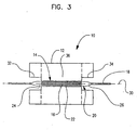
- a stent 16 may be crimped on to a stent delivery catheter 18 utilizing the crimper 10, such as in the manner shown in FIGs. 1-3 .
- the catheter 18 will include a balloon 20, such as is shown in FIG. 3 .
- the stent 16 will typically be mounted on the working portion or body 22 of the balloon 20, which extends between the proximal and distal cones 24 and 26 of the balloon 20.
- the balloon prior to loading the pre-crimped stent 16 onto the balloon 20, the balloon is folded or wrapped about the shaft 28 of the catheter 18 in a reduced pre-deployment state.
- the chamber 14 is defined by the relative position of each member or blades 12.
- the length of the blades 12 correspond to the length of the chamber 14.
- one or more regions along the length of each blade has a height or distance from a longitudinal axis 30 of the chamber, which is greater than a region of the blade adjacent thereto.
- end regions 32 and 34 of the length of each member 12 is a greater distance from the longitudinal axis 30 than the medial region 36 of the blade what extends therebetween.
- the end regions 32 and 34 are differentiated from the region 36 by the step in relative distance from the longitudinal axis 30 shown.
- the region 36 (which in the embodiment shown is disposed about only the portion of the catheter 18 corresponding to the stent 16) will exert a radially inward force on only the stent 16 and/or the working portion 22 of the balloon 20 to crimp the stent 16 onto the balloon 20.
- regions 32 and 34 are maintained a further distance away from the catheter 18 during the crimping procedure.
- the cones 24 and 26 of the balloon may be inflated, heat-set or otherwise manipulated during the crimping process, without being reduced by contact with the blades 12.
- one or both regions 32 and 34 are heated by a heat source 40, such as is depicted in FIGs. 1 and 2 .
- Heat source 40 is operatively engaged to one or both regions 32 and 34 to conductively or otherwise transmit heat (depicted by arrows 50) to the region(s) as desired.
- the region of the blade 12 that is configured for contact with the stent 16 is constructed from or provided with a heat insulating material such as any of a variety of suitable polymers, carbon, non or minimally conductive metals, ceramics, etc.
- the region of the blade 12 that is configured to contact the stent 16 is at least partially constructed of a temperature conducting material such as stainless steel or one or more alloys thereof.
- a region or regions of the blade 12, which are configured to be disposed about the cones 24 and 26 of the balloon 20, are constructed of a heat conducting material such as one or more conductive metals, for example: stainless steel and/or alloys thereof.
- a given blade 12 comprises a first region 32/34 constructed of a heat conducting material and a second region 36 constructed of a heat insulating material. Region 32/34 is operatively engaged to a heat source such as previously described.
- the cones may be heat-set during the crimping process.
- At least a portion of the blade 12, such as for example first region 32/34, is configured to allow a heated fluid such as a liquid or gas (e.g.: heated air, etc.) to be blown through the stepped regions 32/34 and directly onto the cones 24/26.
- a heated fluid such as a liquid or gas (e.g.: heated air, etc.)
- the region 32/34 define one or more fluid transfer lumens 33, of which one is shown in FIG. 4 , that are in fluid communication with the heat source, such as in the manner shown in FIGs. 1 and 2 .
- the balloon 20 is partially pressurized to allow the cones to "puff" out relative to their un-inflated configuration, while the stent 16 is being crimped by region 36 of the blades.
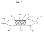
- the regions 32 and 34 of the blades 12 disposed about the respective balloon cones 24 and 26 are then heated in the manner previously described to set the cones in their "puffed” configuration such as in the manner depicted in FIG. 5 .
- edges 25 and 27 of the stent 16 may be protected by the "puffed" cones 24 and 26 which partially abut and overlap the respective edges 25 and 27 of the stent 16 in a desired manner, such as is shown in FIG. 5 .
- the temperature and duration of the heat cycle will vary, and is determined at least in part by the specific polymeric structure and characteristics of the cones.
- the insulated region 36 of the blades 12 remains substantially unaffected by the transmission of heat to the adjacent regions.
- the region 36 of one or more blades 12 may also be configured and/or constructed to conduct heat.
- a coolant fluid such as a liquid or gas is selectively applied to one or more regions of the blade 12.
- multiple crimping heads are utilized which have proportionally different diameter crimping chambers in both the pre-reduction diameter configuration and the reduced diameter configuration.
- the respective crimping chambers effectively form a single stepped diameter chamber, with the number and size of each step dependent on the size of each chamber. It will be recognized that any of a variety of stepped configurations may be provided to a crimping chamber in this manner.
- the stent 16, the delivery system or other portion of the catheter assembly 18 may include one or more areas, bands, coatings, members, etc. that is (are) detectable by imaging modalities such as X-Ray, MRI, ultrasound, etc. In some embodiments at least a portion of the stent and/or adjacent assembly is at least partially radiopaque.
- the crimper 10 shown and described above is particularly suited for use with stent having one or more coatings or other mechanisms for the delivery of a therapeutic agent.
- a therapeutic agent may be a drug or other pharmaceutical product such as non-genetic agents, genetic agents, cellular material, etc.
- suitable non-genetic therapeutic agents include but are not limited to: anti-thrombogenic agents such as heparin, heparin derivatives, vascular cell growth promoters, growth factor inhibitors, Paclitaxel, etc.
- an agent includes a genetic therapeutic agent, such a genetic agent may include but is not limited to: DNA, RNA and their respective derivatives and/or components; hedgehog proteins, etc.
- the cellular material may include but is not limited to: cells of human origin and/or non-human origin as well as their respective components and/or derivatives thereof.
- the polymer agent may be a polystyrene-polyisobutylene-polystyrene triblock copolymer (SIRS), polyethylene oxide, silicone rubber and/or any other suitable substrate.
- SIRS polystyrene-polyisobutylene-polystyrene triblock copolymer
- silicone rubber any other suitable substrate.
Landscapes
- Health & Medical Sciences (AREA)
- Engineering & Computer Science (AREA)
- Biomedical Technology (AREA)
- Cardiology (AREA)
- Oral & Maxillofacial Surgery (AREA)
- Transplantation (AREA)
- Heart & Thoracic Surgery (AREA)
- Vascular Medicine (AREA)
- Life Sciences & Earth Sciences (AREA)
- Animal Behavior & Ethology (AREA)
- General Health & Medical Sciences (AREA)
- Public Health (AREA)
- Veterinary Medicine (AREA)
- Media Introduction/Drainage Providing Device (AREA)
- Materials For Medical Uses (AREA)
- Primary Cells (AREA)
Claims (16)
- Crimpsystem, umfassend:mindestens einen Crimpkopf, wobei der mindestens eine Crimpkopf eine Vielzahl von beweglichen Kontraktionselementen (12) umfasst, wobei die Vielzahl von Kontraktionselementen (12) eine Durchmesserverringerungskammer (14) definieren, die Kammer (14) eine Länge und eine Längsachse aufweist, die Kammer (14) eine Konfiguration mit verringertem Durchmesser und eine Konfiguration vor der Verringerung des Durchmessers hat, jedes Element (12) eine Länge hat, die Länge von jedem Element (12) der Länge der Kammer (14) entspricht, jedes Element (12) sowohl in der Konfiguration mit verringertem Durchmesser wie auch in der Konfiguration vor der Verringerung des Durchmessers in einem Abstand von der Längsachse positioniert ist, wobei ein erstes Gebiet (32, 34) der Länge von jedem Element (12) in einem größeren Abstand von der Längsachse ist als ein zweites Gebiet (36) der Länge von jedem Element (12), dadurch gekennzeichnet, dass das erste Gebiet (32, 34) von jedem Element (12) aus einem Temperatur leitenden Material aufgebaut ist und das zweite Gebiet (36) der Länge von jedem Element (12) aus einem Temperatur isolierenden Material aufgebaut ist, das erste Gebiet (32, 34) in wirksamem Eingriff mit einer Wärmequelle (40) ist, um Wärme auf das Gebiet (32, 34) zu übertragen, und das System konfiguriert ist, ein Kühlfluid wahlweise auf eines oder mehrere Gebiete (32, 34, 36) der Elemente (12) aufzubringen.
- System gemäß Anspruch 1, wobei das erste Gebiet (32, 34) und das zweite Gebiet (36) durch eine Stufe getrennt sind.
- System gemäß Anspruch 1, wobei das Temperatur isolierende Material aus mindestens einem Mitglied der Gruppe bestehend aus Keramik, polymeren Materialien, Kohlenstoff und irgendeiner Kombination davon ausgewählt ist.
- System gemäß Anspruch 1, wobei das erste Gebiet (32, 34) von jedem Element (12) aus rostfreiem Stahl oder einer Legierung davon aufgebaut ist.
- System gemäß Anspruch 1, wobei die Wärmequelle (40) leitfähig in Eingriff mit dem ersten Gebiet (32, 34) ist.
- System gemäß Anspruch 1, umfassend eine ersten Crimpkopf und einen angrenzend daran positionierten zweiten Crimpkopf.
- System gemäß Anspruch 1, wobei das erste Gebiet (32, 34) der Länge von jedem Element (12) ein erstes Endgebiet (32) und ein zweites Endgebiet (34) umfasst, und das zweite Endgebiet (36) der Länge von jedem Element (12) ein sich dazwischen erstreckendes, mittleres Gebiet umfasst.
- System gemäß Anspruch 7, ferner umfassend:einen Ballon (20) mit einem sich zwischen proximalen und distalen Konussen (24, 26) des Ballons (20) erstreckenden Wirkabschnitt (22); undeinen Stent (16), der auf dem Wirkabschnitt (22) des Ballons (20) angebracht ist;wobei der Stent (16) und der Ballon (20) in der Durchmesserverringerungskammer (14) positioniert sind.
- System gemäß Anspruch 7, wobei das mittlere Gebiet eine radial nach Innen gerichtete Kraft auf lediglich den Stent (16) und den Wirkabschnitt (22) des Ballons (20) ausübt, um den Stent (16) auf den Ballon (20) zu crimpen.
- System gemäß Anspruch 7, wobei der Stent mit einem therapeutischen Mittel beschichtet ist.
- Verfahren zum Crimpen eines Stents (16) auf einen Ballonkatheter (18), umfassend die Schritte von:Bereitstellen eines Katheters (18), wobei der Katheter (18) einen Katheterschaft und einen über den Schaft gefalteten Ballon (20) aufweist, der Ballon (20) ein proximales Konusgebiet (24), ein distales Konusgebiet (26) und ein Körpergebiet (22) dazwischen hat;Platzieren eines Stents (16) über das Körpergebiet (22) des Ballons (20), wobei der Stent (16) und der Katheter (18) kombiniert sind, um ein Stentfreisetzungssystem bereitzustellen;Bereitstellen von einem Crimpmechanismus, wobei der Crimpmechanismus umfasst:mindestens einen Crimpkopf, wobei der mindestens eine Crimpkopf eine Vielzahl von beweglichen Kontraktionselementen (12) umfasst, wobei die Vielzahl von Kontraktionselementen (12) eine Durchmesserverringerungskammer (14) definieren, die Kammer (14) eine Länge und eine Längsachse aufweist, die Kammer (14) eine Konfiguration mit verringertem Durchmesser und eine Konfiguration vor der Verringerung des Durchmessers hat, jedes Element (12) eine Länge hat, die Länge von jedem Element (12) der Länge der Kammer (14) entspricht, sowohl in der Konfiguration mit verringertem Durchmesser wie auch in der Konfiguration vor der Verringerung des Durchmessers jedes Element (12) in einem Abstand von der Längsachse positioniert ist, wobei ein erstes Gebiet (32, 34) der Länge von jedem Element (12) in einem größeren Abstand von der Längsachse ist als ein zweites Gebiet (36) der Länge von jedem Element (12),das erste Gebiet (32, 34) in wirksamen Eingriff mit einer Temperaturquelle (40) bringen, um Wärme auf das erste Gebiet (32, 34) zu übertragen, und ein Kühlfluid wahlweise auf eines oder mehrere Gebiete (32, 34, 36) der Elemente (12) aufbringen,Einbringen von mindestens einem Teil des durch den Stent (16) und den Ballon (20) definierten Stentfreisetzungssystems in die Durchmesserverringerungskammer (14) in der Konfiguration vor der Verringerung des Durchmessers,wobei das erste Gebiet (32, 34) des Elementes (12) längsseitig über mindestens einem aus dem proximalen Konusgebiet (24) und dem distalen Konusgebiet (26) des Ballons (20) angeordnet ist, das zweite Gebiet (36) des Elementes (12) längsseitig über dem Stent (16) angeordnet ist;Crimpen des Stents (16) auf das Ballonkörpergebiet (22) des Katheters (18) durch Verringern des Durchmessers der Kammer (14) zu der Konfiguration mit verringertem Durchmesser; wobei das zweite Gebiet (36) von jedem Element (12) längsseitig auf den Stent (16) eine radial nach Innen gerichtete Kraft ausübt;Aufblähen des mindestens einen proximalen Konusgebietes (24) und distalen Konusgebietes (26) des Ballons (20); undErwärmen des ersten Gebietes (32, 34) von jedem Element (12), derart dass das zweite Gebiet (36) durch die Übertragung von Wärme auf das angrenzende Gebiet im wesentlichen nicht betroffen ist.
- Verfahren gemäß Anspruch 11, wobei der Stent (16) einen Stentkörper umfasst, wobei der Körper mindestens teilweise mit mindestens einem therapeutischen Mittel beschichtet ist.
- Verfahren gemäß Anspruch 11, wobei das erste Gebiet (32, 34) von jedem Element (12) aus einem Temperatur leitenden Material aufgebaut ist und das zweite Gebiet (36) von jedem Element (12) aus einem Temperatur isolierenden Material aufgebaut ist.
- Verfahren gemäß Anspruch 11, wobei das erste Gebiet (32, 34) von jedem Element (12) aus einem Temperatur isolierenden Material aufgebaut ist und das zweite Gebiet (36) von jedem Element (12) aus einem Temperatur leitenden Material aufgebaut ist.
- Verfahren gemäß Anspruch 11, wobei die Konusse (24, 26) des Ballons (20) während des Crimpvorgangs wärmegehärtet werden.
- Verfahren gemäß Anspruch 11, wobei der Ballon (20) teilweise mit Druck beaufschlagt wird, während der Stent (16) gecrimpt wird.
Applications Claiming Priority (2)
| Application Number | Priority Date | Filing Date | Title |
|---|---|---|---|
| US11/167,507 US8099851B2 (en) | 2005-06-27 | 2005-06-27 | Crimping and edge protection elements |
| PCT/US2006/008628 WO2007001515A1 (en) | 2005-06-27 | 2006-03-10 | Crimping and edge protection elements |
Publications (2)
| Publication Number | Publication Date |
|---|---|
| EP1903983A1 EP1903983A1 (de) | 2008-04-02 |
| EP1903983B1 true EP1903983B1 (de) | 2010-07-28 |
Family
ID=36577536
Family Applications (1)
| Application Number | Title | Priority Date | Filing Date |
|---|---|---|---|
| EP06737773A Expired - Lifetime EP1903983B1 (de) | 2005-06-27 | 2006-03-10 | Crimping- und kantenschutzelemente |
Country Status (7)
| Country | Link |
|---|---|
| US (1) | US8099851B2 (de) |
| EP (1) | EP1903983B1 (de) |
| JP (1) | JP2008543489A (de) |
| AT (1) | ATE475374T1 (de) |
| CA (1) | CA2607919A1 (de) |
| DE (1) | DE602006015811D1 (de) |
| WO (1) | WO2007001515A1 (de) |
Families Citing this family (12)
| Publication number | Priority date | Publication date | Assignee | Title |
|---|---|---|---|---|
| US6863683B2 (en) | 2001-09-19 | 2005-03-08 | Abbott Laboratoris Vascular Entities Limited | Cold-molding process for loading a stent onto a stent delivery system |
| US8333000B2 (en) | 2006-06-19 | 2012-12-18 | Advanced Cardiovascular Systems, Inc. | Methods for improving stent retention on a balloon catheter |
| US7886419B2 (en) * | 2006-07-18 | 2011-02-15 | Advanced Cardiovascular Systems, Inc. | Stent crimping apparatus and method |
| US8042251B2 (en) * | 2008-05-21 | 2011-10-25 | Boston Scientific Scimed, Inc. | Systems and methods for heating and cooling during stent crimping |
| EP2147663A1 (de) * | 2008-07-23 | 2010-01-27 | Abbott Laboratories Vascular Enterprises Limited | Vorrichtung zur Verhinderung der Stent-Bewegung |
| EP2196174B1 (de) * | 2008-12-12 | 2014-02-26 | Abbott Laboratories Vascular Enterprises Limited | Verfahren zum Laden eines Stents auf das Stenteinbringungssystem |
| US20110106234A1 (en) * | 2009-10-30 | 2011-05-05 | Axel Grandt | Interluminal medical treatment devices and methods |
| US9192738B2 (en) * | 2012-04-25 | 2015-11-24 | Medtronic Vascular Galway | Devices and methods for crimping medical devices |
| US10195025B2 (en) * | 2014-05-12 | 2019-02-05 | Edwards Lifesciences Corporation | Prosthetic heart valve |
| US12115089B2 (en) | 2020-03-26 | 2024-10-15 | Medtronic, Inc. | Clamshell iris-style crimper for medical devices |
| US11844713B2 (en) | 2020-08-06 | 2023-12-19 | Medtronic, Inc. | Iris-style crimpers for medical devices |
| CN114617672A (zh) * | 2020-12-10 | 2022-06-14 | 上海纽脉医疗科技有限公司 | 一种压握装置及其使用方法 |
Family Cites Families (34)
| Publication number | Priority date | Publication date | Assignee | Title |
|---|---|---|---|---|
| US6168921B1 (en) | 1996-07-19 | 2001-01-02 | Udo Riss | Method for the quantitative and/or qualitative determination of atoms or molecules |
| US5972016A (en) | 1997-04-22 | 1999-10-26 | Advanced Cardiovascular Systems, Inc. | Stent crimping device and method of use |
| US5992000A (en) | 1997-10-16 | 1999-11-30 | Scimed Life Systems, Inc. | Stent crimper |
| US6769161B2 (en) | 1997-10-16 | 2004-08-03 | Scimed Life Systems, Inc. | Radial stent crimper |
| US6082990A (en) | 1998-02-17 | 2000-07-04 | Advanced Cardiovascular Systems, Inc. | Stent crimping tool |
| US6063092A (en) | 1998-04-07 | 2000-05-16 | Medtronic Inc. | Heat set and crimping process to optimize stent retention |
| US5974652A (en) | 1998-05-05 | 1999-11-02 | Advanced Cardiovascular Systems, Inc. | Method and apparatus for uniformly crimping a stent onto a catheter |
| US6092273A (en) | 1998-07-28 | 2000-07-25 | Advanced Cardiovascular Systems, Inc. | Method and apparatus for a stent crimping device |
| US6074381A (en) | 1998-10-22 | 2000-06-13 | Isostent, Inc. | Cylindrical roller stent crimper apparatus with radiation shield |
| SG76636A1 (en) | 1998-12-22 | 2000-11-21 | Medinol Ltd | Apparatus and method for securing a stent on a balloon |
| US6360577B2 (en) | 1999-09-22 | 2002-03-26 | Scimed Life Systems, Inc. | Apparatus for contracting, or crimping stents |
| US6387117B1 (en) | 1999-09-22 | 2002-05-14 | Scimed Life Systems, Inc. | Stent crimping system |
| US6352547B1 (en) | 1999-09-22 | 2002-03-05 | Scimed Life Systems, Inc. | Stent crimping system |
| US6481262B2 (en) * | 1999-12-30 | 2002-11-19 | Advanced Cardiovascular Systems, Inc. | Stent crimping tool |
| US6387118B1 (en) | 2000-04-20 | 2002-05-14 | Scimed Life Systems, Inc. | Non-crimped stent delivery system |
| US6629350B2 (en) * | 2000-06-08 | 2003-10-07 | Tom Motsenbocker | Stent crimping apparatus and method |
| US6568235B1 (en) * | 2000-08-10 | 2003-05-27 | Advanced Cardiovascular Systems, Inc. | Assembly for crimping an intraluminal device or measuring the radial strength of the intraluminal device and method of use |
| US6739033B2 (en) * | 2001-03-29 | 2004-05-25 | Scimed Life Systems, Inc. | Thermal regulation of a coated work-piece during the reconfiguration of the coated work-piece |
| US6718814B2 (en) * | 2001-04-06 | 2004-04-13 | Computer Age Engineering | Swaging die assembly having compressible spacing element |
| US6666880B1 (en) * | 2001-06-19 | 2003-12-23 | Advised Cardiovascular Systems, Inc. | Method and system for securing a coated stent to a balloon catheter |
| US6745445B2 (en) | 2002-10-29 | 2004-06-08 | Bard Peripheral Vascular, Inc. | Stent compression method |
| US7487579B2 (en) * | 2003-03-12 | 2009-02-10 | Boston Scientific Scimed, Inc. | Methods of making medical devices |
| US20050118344A1 (en) | 2003-12-01 | 2005-06-02 | Pacetti Stephen D. | Temperature controlled crimping |
| US7284401B2 (en) * | 2004-01-12 | 2007-10-23 | Boston Scientific Scimed, Inc. | Stent reducing system and device |
| US7316147B2 (en) * | 2004-01-29 | 2008-01-08 | Boston Scientific Scimed, Inc. | Apparatuses for crimping and loading of intraluminal medical devices |
| US7225518B2 (en) * | 2004-02-23 | 2007-06-05 | Boston Scientific Scimed, Inc. | Apparatus for crimping a stent assembly |
| US7207204B2 (en) * | 2004-02-26 | 2007-04-24 | Boston Scientific Scimed, Inc. | Crimper |
| US7143625B2 (en) * | 2004-04-16 | 2006-12-05 | Boston Scientific Scimed, Inc. | Stent crimper |
| US7021114B2 (en) * | 2004-04-16 | 2006-04-04 | Boston Scientific Scimed, Inc. | Stent crimper |
| US7763198B2 (en) * | 2005-04-12 | 2010-07-27 | Abbott Cardiovascular Systems Inc. | Method for retaining a vascular stent on a catheter |
| US7947207B2 (en) * | 2005-04-12 | 2011-05-24 | Abbott Cardiovascular Systems Inc. | Method for retaining a vascular stent on a catheter |
| US7563400B2 (en) * | 2005-04-12 | 2009-07-21 | Advanced Cardiovascular Systems, Inc. | Method of stent mounting to form a balloon catheter having improved retention of a drug delivery stent |
| US7673379B1 (en) * | 2007-05-11 | 2010-03-09 | Abbott Cardiovascular Systems Inc. | Method of producing a stent-balloon assembly |
| US8042251B2 (en) * | 2008-05-21 | 2011-10-25 | Boston Scientific Scimed, Inc. | Systems and methods for heating and cooling during stent crimping |
-
2005
- 2005-06-27 US US11/167,507 patent/US8099851B2/en active Active
-
2006
- 2006-03-10 WO PCT/US2006/008628 patent/WO2007001515A1/en not_active Ceased
- 2006-03-10 JP JP2008518131A patent/JP2008543489A/ja not_active Withdrawn
- 2006-03-10 DE DE602006015811T patent/DE602006015811D1/de not_active Expired - Lifetime
- 2006-03-10 CA CA002607919A patent/CA2607919A1/en not_active Abandoned
- 2006-03-10 AT AT06737773T patent/ATE475374T1/de not_active IP Right Cessation
- 2006-03-10 EP EP06737773A patent/EP1903983B1/de not_active Expired - Lifetime
Also Published As
| Publication number | Publication date |
|---|---|
| US20060288561A1 (en) | 2006-12-28 |
| DE602006015811D1 (de) | 2010-09-09 |
| CA2607919A1 (en) | 2007-01-04 |
| ATE475374T1 (de) | 2010-08-15 |
| US8099851B2 (en) | 2012-01-24 |
| WO2007001515A1 (en) | 2007-01-04 |
| EP1903983A1 (de) | 2008-04-02 |
| JP2008543489A (ja) | 2008-12-04 |
Similar Documents
| Publication | Publication Date | Title |
|---|---|---|
| US8042373B2 (en) | Method and apparatus for reducing a stent | |
| EP1727649B1 (de) | Vorrichtung und verfahren zum quetschen einer stentanordnung | |
| EP2124848B1 (de) | Stentdesign mit streben mit unterschiedlichen winkeln und unterschiedlicher steifheit | |
| EP1887973B1 (de) | Gezielte behandlung von seitenzweigblättern von stents | |
| JP4927836B2 (ja) | 基端方向に拡がるステントを配備するシステム及び方法 | |
| EP2068762B1 (de) | Säulen-zellfunktionen zur verbesserung der verbreitung von wirkstoffen und des gerüsts eines stents | |
| WO2005084382A2 (en) | Stent delivery apparatus and methods | |
| US8099851B2 (en) | Crimping and edge protection elements | |
| US12076258B2 (en) | Selective stent crimping | |
| US20080086192A1 (en) | Stent protector design | |
| AU2013336675A1 (en) | Crimping method for bioresorbable stents | |
| EP1919407B1 (de) | Durch laserabtragung erzeugte elastomerhüllenprofile zur fixierung von stents | |
| US20070123970A1 (en) | Bifurcation stent with overlapping crimped struts | |
| AU2012200419A1 (en) | Wire with compliant sheath | |
| US20100228337A1 (en) | Mirror image stent and method of use | |
| JP6050926B2 (ja) | ステントデリバリーシステムの製造方法 | |
| CA2630047A1 (en) | Bifurcation stent delivery system | |
| US20070032851A1 (en) | Protection by electroactive polymer sleeve |
Legal Events
| Date | Code | Title | Description |
|---|---|---|---|
| PUAI | Public reference made under article 153(3) epc to a published international application that has entered the european phase |
Free format text: ORIGINAL CODE: 0009012 |
|
| 17P | Request for examination filed |
Effective date: 20071113 |
|
| AK | Designated contracting states |
Kind code of ref document: A1 Designated state(s): AT BE BG CH CY CZ DE DK EE ES FI FR GB GR HU IE IS IT LI LT LU LV MC NL PL PT RO SE SI SK TR |
|
| DAX | Request for extension of the european patent (deleted) | ||
| 17Q | First examination report despatched |
Effective date: 20090520 |
|
| GRAP | Despatch of communication of intention to grant a patent |
Free format text: ORIGINAL CODE: EPIDOSNIGR1 |
|
| GRAS | Grant fee paid |
Free format text: ORIGINAL CODE: EPIDOSNIGR3 |
|
| GRAA | (expected) grant |
Free format text: ORIGINAL CODE: 0009210 |
|
| AK | Designated contracting states |
Kind code of ref document: B1 Designated state(s): AT BE BG CH CY CZ DE DK EE ES FI FR GB GR HU IE IS IT LI LT LU LV MC NL PL PT RO SE SI SK TR |
|
| REG | Reference to a national code |
Ref country code: GB Ref legal event code: FG4D |
|
| REG | Reference to a national code |
Ref country code: CH Ref legal event code: EP |
|
| REG | Reference to a national code |
Ref country code: IE Ref legal event code: FG4D |
|
| REF | Corresponds to: |
Ref document number: 602006015811 Country of ref document: DE Date of ref document: 20100909 Kind code of ref document: P |
|
| REG | Reference to a national code |
Ref country code: NL Ref legal event code: VDEP Effective date: 20100728 |
|
| LTIE | Lt: invalidation of european patent or patent extension |
Effective date: 20100728 |
|
| PG25 | Lapsed in a contracting state [announced via postgrant information from national office to epo] |
Ref country code: AT Free format text: LAPSE BECAUSE OF FAILURE TO SUBMIT A TRANSLATION OF THE DESCRIPTION OR TO PAY THE FEE WITHIN THE PRESCRIBED TIME-LIMIT Effective date: 20100728 Ref country code: NL Free format text: LAPSE BECAUSE OF FAILURE TO SUBMIT A TRANSLATION OF THE DESCRIPTION OR TO PAY THE FEE WITHIN THE PRESCRIBED TIME-LIMIT Effective date: 20100728 Ref country code: LT Free format text: LAPSE BECAUSE OF FAILURE TO SUBMIT A TRANSLATION OF THE DESCRIPTION OR TO PAY THE FEE WITHIN THE PRESCRIBED TIME-LIMIT Effective date: 20100728 Ref country code: FI Free format text: LAPSE BECAUSE OF FAILURE TO SUBMIT A TRANSLATION OF THE DESCRIPTION OR TO PAY THE FEE WITHIN THE PRESCRIBED TIME-LIMIT Effective date: 20100728 |
|
| PG25 | Lapsed in a contracting state [announced via postgrant information from national office to epo] |
Ref country code: PL Free format text: LAPSE BECAUSE OF FAILURE TO SUBMIT A TRANSLATION OF THE DESCRIPTION OR TO PAY THE FEE WITHIN THE PRESCRIBED TIME-LIMIT Effective date: 20100728 Ref country code: BG Free format text: LAPSE BECAUSE OF FAILURE TO SUBMIT A TRANSLATION OF THE DESCRIPTION OR TO PAY THE FEE WITHIN THE PRESCRIBED TIME-LIMIT Effective date: 20101028 Ref country code: IS Free format text: LAPSE BECAUSE OF FAILURE TO SUBMIT A TRANSLATION OF THE DESCRIPTION OR TO PAY THE FEE WITHIN THE PRESCRIBED TIME-LIMIT Effective date: 20101128 Ref country code: PT Free format text: LAPSE BECAUSE OF FAILURE TO SUBMIT A TRANSLATION OF THE DESCRIPTION OR TO PAY THE FEE WITHIN THE PRESCRIBED TIME-LIMIT Effective date: 20101129 Ref country code: SI Free format text: LAPSE BECAUSE OF FAILURE TO SUBMIT A TRANSLATION OF THE DESCRIPTION OR TO PAY THE FEE WITHIN THE PRESCRIBED TIME-LIMIT Effective date: 20100728 Ref country code: CY Free format text: LAPSE BECAUSE OF FAILURE TO SUBMIT A TRANSLATION OF THE DESCRIPTION OR TO PAY THE FEE WITHIN THE PRESCRIBED TIME-LIMIT Effective date: 20100728 |
|
| PG25 | Lapsed in a contracting state [announced via postgrant information from national office to epo] |
Ref country code: BE Free format text: LAPSE BECAUSE OF FAILURE TO SUBMIT A TRANSLATION OF THE DESCRIPTION OR TO PAY THE FEE WITHIN THE PRESCRIBED TIME-LIMIT Effective date: 20100728 Ref country code: SE Free format text: LAPSE BECAUSE OF FAILURE TO SUBMIT A TRANSLATION OF THE DESCRIPTION OR TO PAY THE FEE WITHIN THE PRESCRIBED TIME-LIMIT Effective date: 20100728 Ref country code: LV Free format text: LAPSE BECAUSE OF FAILURE TO SUBMIT A TRANSLATION OF THE DESCRIPTION OR TO PAY THE FEE WITHIN THE PRESCRIBED TIME-LIMIT Effective date: 20100728 Ref country code: GR Free format text: LAPSE BECAUSE OF FAILURE TO SUBMIT A TRANSLATION OF THE DESCRIPTION OR TO PAY THE FEE WITHIN THE PRESCRIBED TIME-LIMIT Effective date: 20101029 |
|
| PG25 | Lapsed in a contracting state [announced via postgrant information from national office to epo] |
Ref country code: DK Free format text: LAPSE BECAUSE OF FAILURE TO SUBMIT A TRANSLATION OF THE DESCRIPTION OR TO PAY THE FEE WITHIN THE PRESCRIBED TIME-LIMIT Effective date: 20100728 |
|
| PG25 | Lapsed in a contracting state [announced via postgrant information from national office to epo] |
Ref country code: SK Free format text: LAPSE BECAUSE OF FAILURE TO SUBMIT A TRANSLATION OF THE DESCRIPTION OR TO PAY THE FEE WITHIN THE PRESCRIBED TIME-LIMIT Effective date: 20100728 Ref country code: CZ Free format text: LAPSE BECAUSE OF FAILURE TO SUBMIT A TRANSLATION OF THE DESCRIPTION OR TO PAY THE FEE WITHIN THE PRESCRIBED TIME-LIMIT Effective date: 20100728 Ref country code: EE Free format text: LAPSE BECAUSE OF FAILURE TO SUBMIT A TRANSLATION OF THE DESCRIPTION OR TO PAY THE FEE WITHIN THE PRESCRIBED TIME-LIMIT Effective date: 20100728 Ref country code: RO Free format text: LAPSE BECAUSE OF FAILURE TO SUBMIT A TRANSLATION OF THE DESCRIPTION OR TO PAY THE FEE WITHIN THE PRESCRIBED TIME-LIMIT Effective date: 20100728 Ref country code: IT Free format text: LAPSE BECAUSE OF FAILURE TO SUBMIT A TRANSLATION OF THE DESCRIPTION OR TO PAY THE FEE WITHIN THE PRESCRIBED TIME-LIMIT Effective date: 20100728 |
|
| PLBE | No opposition filed within time limit |
Free format text: ORIGINAL CODE: 0009261 |
|
| STAA | Information on the status of an ep patent application or granted ep patent |
Free format text: STATUS: NO OPPOSITION FILED WITHIN TIME LIMIT |
|
| PG25 | Lapsed in a contracting state [announced via postgrant information from national office to epo] |
Ref country code: ES Free format text: LAPSE BECAUSE OF FAILURE TO SUBMIT A TRANSLATION OF THE DESCRIPTION OR TO PAY THE FEE WITHIN THE PRESCRIBED TIME-LIMIT Effective date: 20101108 |
|
| 26N | No opposition filed |
Effective date: 20110429 |
|
| REG | Reference to a national code |
Ref country code: DE Ref legal event code: R097 Ref document number: 602006015811 Country of ref document: DE Effective date: 20110429 |
|
| PG25 | Lapsed in a contracting state [announced via postgrant information from national office to epo] |
Ref country code: MC Free format text: LAPSE BECAUSE OF NON-PAYMENT OF DUE FEES Effective date: 20110331 |
|
| REG | Reference to a national code |
Ref country code: CH Ref legal event code: PL |
|
| GBPC | Gb: european patent ceased through non-payment of renewal fee |
Effective date: 20110310 |
|
| REG | Reference to a national code |
Ref country code: FR Ref legal event code: ST Effective date: 20111130 |
|
| PG25 | Lapsed in a contracting state [announced via postgrant information from national office to epo] |
Ref country code: LI Free format text: LAPSE BECAUSE OF NON-PAYMENT OF DUE FEES Effective date: 20110331 Ref country code: CH Free format text: LAPSE BECAUSE OF NON-PAYMENT OF DUE FEES Effective date: 20110331 Ref country code: FR Free format text: LAPSE BECAUSE OF NON-PAYMENT OF DUE FEES Effective date: 20110331 |
|
| PG25 | Lapsed in a contracting state [announced via postgrant information from national office to epo] |
Ref country code: GB Free format text: LAPSE BECAUSE OF NON-PAYMENT OF DUE FEES Effective date: 20110310 |
|
| PG25 | Lapsed in a contracting state [announced via postgrant information from national office to epo] |
Ref country code: LU Free format text: LAPSE BECAUSE OF NON-PAYMENT OF DUE FEES Effective date: 20110310 |
|
| PG25 | Lapsed in a contracting state [announced via postgrant information from national office to epo] |
Ref country code: TR Free format text: LAPSE BECAUSE OF FAILURE TO SUBMIT A TRANSLATION OF THE DESCRIPTION OR TO PAY THE FEE WITHIN THE PRESCRIBED TIME-LIMIT Effective date: 20100728 |
|
| PG25 | Lapsed in a contracting state [announced via postgrant information from national office to epo] |
Ref country code: HU Free format text: LAPSE BECAUSE OF FAILURE TO SUBMIT A TRANSLATION OF THE DESCRIPTION OR TO PAY THE FEE WITHIN THE PRESCRIBED TIME-LIMIT Effective date: 20100728 |
|
| REG | Reference to a national code |
Ref country code: DE Ref legal event code: R082 Ref document number: 602006015811 Country of ref document: DE Representative=s name: VOSSIUS & PARTNER PATENTANWAELTE RECHTSANWAELT, DE |
|
| REG | Reference to a national code |
Ref country code: DE Ref legal event code: R082 Ref document number: 602006015811 Country of ref document: DE Representative=s name: VOSSIUS & PARTNER PATENTANWAELTE RECHTSANWAELT, DE |
|
| REG | Reference to a national code |
Ref country code: DE Ref legal event code: R082 Ref document number: 602006015811 Country of ref document: DE Representative=s name: VOSSIUS & PARTNER PATENTANWAELTE RECHTSANWAELT, DE Effective date: 20141026 Ref country code: DE Ref legal event code: R082 Ref document number: 602006015811 Country of ref document: DE Representative=s name: VOSSIUS & PARTNER PATENTANWAELTE RECHTSANWAELT, DE Effective date: 20150202 Ref country code: DE Ref legal event code: R081 Ref document number: 602006015811 Country of ref document: DE Owner name: BOSTON SCIENTIFIC LIMITED, BM Free format text: FORMER OWNER: BOSTON SCIENTIFIC LTD., CHRIST CHURCH, BB Effective date: 20150202 |
|
| PGFP | Annual fee paid to national office [announced via postgrant information from national office to epo] |
Ref country code: IE Payment date: 20230222 Year of fee payment: 18 |
|
| PGFP | Annual fee paid to national office [announced via postgrant information from national office to epo] |
Ref country code: DE Payment date: 20230221 Year of fee payment: 18 |
|
| REG | Reference to a national code |
Ref country code: DE Ref legal event code: R119 Ref document number: 602006015811 Country of ref document: DE |
|
| PG25 | Lapsed in a contracting state [announced via postgrant information from national office to epo] |
Ref country code: DE Free format text: LAPSE BECAUSE OF NON-PAYMENT OF DUE FEES Effective date: 20241001 |
|
| PG25 | Lapsed in a contracting state [announced via postgrant information from national office to epo] |
Ref country code: IE Free format text: LAPSE BECAUSE OF NON-PAYMENT OF DUE FEES Effective date: 20240310 |
|
| PG25 | Lapsed in a contracting state [announced via postgrant information from national office to epo] |
Ref country code: IE Free format text: LAPSE BECAUSE OF NON-PAYMENT OF DUE FEES Effective date: 20240310 Ref country code: DE Free format text: LAPSE BECAUSE OF NON-PAYMENT OF DUE FEES Effective date: 20241001 |