EP1903984B1 - Stent und verfahren zu seiner herstellung - Google Patents
Stent und verfahren zu seiner herstellung Download PDFInfo
- Publication number
- EP1903984B1 EP1903984B1 EP06769196.4A EP06769196A EP1903984B1 EP 1903984 B1 EP1903984 B1 EP 1903984B1 EP 06769196 A EP06769196 A EP 06769196A EP 1903984 B1 EP1903984 B1 EP 1903984B1
- Authority
- EP
- European Patent Office
- Prior art keywords
- peaks
- starting point
- track
- valleys
- stent
- Prior art date
- Legal status (The legal status is an assumption and is not a legal conclusion. Google has not performed a legal analysis and makes no representation as to the accuracy of the status listed.)
- Active
Links
Images



Classifications
-
- A—HUMAN NECESSITIES
- A61—MEDICAL OR VETERINARY SCIENCE; HYGIENE
- A61F—FILTERS IMPLANTABLE INTO BLOOD VESSELS; PROSTHESES; DEVICES PROVIDING PATENCY TO, OR PREVENTING COLLAPSING OF, TUBULAR STRUCTURES OF THE BODY, e.g. STENTS; ORTHOPAEDIC, NURSING OR CONTRACEPTIVE DEVICES; FOMENTATION; TREATMENT OR PROTECTION OF EYES OR EARS; BANDAGES, DRESSINGS OR ABSORBENT PADS; FIRST-AID KITS
- A61F2/00—Filters implantable into blood vessels; Prostheses, i.e. artificial substitutes or replacements for parts of the body; Appliances for connecting them with the body; Devices providing patency to, or preventing collapsing of, tubular structures of the body, e.g. stents
- A61F2/82—Devices providing patency to, or preventing collapsing of, tubular structures of the body, e.g. stents
-
- A—HUMAN NECESSITIES
- A61—MEDICAL OR VETERINARY SCIENCE; HYGIENE
- A61F—FILTERS IMPLANTABLE INTO BLOOD VESSELS; PROSTHESES; DEVICES PROVIDING PATENCY TO, OR PREVENTING COLLAPSING OF, TUBULAR STRUCTURES OF THE BODY, e.g. STENTS; ORTHOPAEDIC, NURSING OR CONTRACEPTIVE DEVICES; FOMENTATION; TREATMENT OR PROTECTION OF EYES OR EARS; BANDAGES, DRESSINGS OR ABSORBENT PADS; FIRST-AID KITS
- A61F2/00—Filters implantable into blood vessels; Prostheses, i.e. artificial substitutes or replacements for parts of the body; Appliances for connecting them with the body; Devices providing patency to, or preventing collapsing of, tubular structures of the body, e.g. stents
- A61F2/82—Devices providing patency to, or preventing collapsing of, tubular structures of the body, e.g. stents
- A61F2/86—Stents in a form characterised by the wire-like elements; Stents in the form characterised by a net-like or mesh-like structure
- A61F2/90—Stents in a form characterised by the wire-like elements; Stents in the form characterised by a net-like or mesh-like structure characterised by a net-like or mesh-like structure
-
- A—HUMAN NECESSITIES
- A61—MEDICAL OR VETERINARY SCIENCE; HYGIENE
- A61F—FILTERS IMPLANTABLE INTO BLOOD VESSELS; PROSTHESES; DEVICES PROVIDING PATENCY TO, OR PREVENTING COLLAPSING OF, TUBULAR STRUCTURES OF THE BODY, e.g. STENTS; ORTHOPAEDIC, NURSING OR CONTRACEPTIVE DEVICES; FOMENTATION; TREATMENT OR PROTECTION OF EYES OR EARS; BANDAGES, DRESSINGS OR ABSORBENT PADS; FIRST-AID KITS
- A61F2/00—Filters implantable into blood vessels; Prostheses, i.e. artificial substitutes or replacements for parts of the body; Appliances for connecting them with the body; Devices providing patency to, or preventing collapsing of, tubular structures of the body, e.g. stents
- A61F2/82—Devices providing patency to, or preventing collapsing of, tubular structures of the body, e.g. stents
- A61F2/86—Stents in a form characterised by the wire-like elements; Stents in the form characterised by a net-like or mesh-like structure
-
- A—HUMAN NECESSITIES
- A61—MEDICAL OR VETERINARY SCIENCE; HYGIENE
- A61F—FILTERS IMPLANTABLE INTO BLOOD VESSELS; PROSTHESES; DEVICES PROVIDING PATENCY TO, OR PREVENTING COLLAPSING OF, TUBULAR STRUCTURES OF THE BODY, e.g. STENTS; ORTHOPAEDIC, NURSING OR CONTRACEPTIVE DEVICES; FOMENTATION; TREATMENT OR PROTECTION OF EYES OR EARS; BANDAGES, DRESSINGS OR ABSORBENT PADS; FIRST-AID KITS
- A61F2/00—Filters implantable into blood vessels; Prostheses, i.e. artificial substitutes or replacements for parts of the body; Appliances for connecting them with the body; Devices providing patency to, or preventing collapsing of, tubular structures of the body, e.g. stents
- A61F2/82—Devices providing patency to, or preventing collapsing of, tubular structures of the body, e.g. stents
- A61F2/86—Stents in a form characterised by the wire-like elements; Stents in the form characterised by a net-like or mesh-like structure
- A61F2/89—Stents in a form characterised by the wire-like elements; Stents in the form characterised by a net-like or mesh-like structure the wire-like elements comprising two or more adjacent rings flexibly connected by separate members
-
- A—HUMAN NECESSITIES
- A61—MEDICAL OR VETERINARY SCIENCE; HYGIENE
- A61F—FILTERS IMPLANTABLE INTO BLOOD VESSELS; PROSTHESES; DEVICES PROVIDING PATENCY TO, OR PREVENTING COLLAPSING OF, TUBULAR STRUCTURES OF THE BODY, e.g. STENTS; ORTHOPAEDIC, NURSING OR CONTRACEPTIVE DEVICES; FOMENTATION; TREATMENT OR PROTECTION OF EYES OR EARS; BANDAGES, DRESSINGS OR ABSORBENT PADS; FIRST-AID KITS
- A61F2240/00—Manufacturing or designing of prostheses classified in groups A61F2/00 - A61F2/26 or A61F2/82 or A61F9/00 or A61F11/00 or subgroups thereof
- A61F2240/001—Designing or manufacturing processes
-
- D—TEXTILES; PAPER
- D10—INDEXING SCHEME ASSOCIATED WITH SUBLASSES OF SECTION D, RELATING TO TEXTILES
- D10B—INDEXING SCHEME ASSOCIATED WITH SUBLASSES OF SECTION D, RELATING TO TEXTILES
- D10B2509/00—Medical; Hygiene
- D10B2509/06—Vascular grafts; stents
Definitions
- the present invention relates to a stent and a method for manufacturing the same, and more particularly, to the stent that is improved in a quality by preventing the damage of a material thereof during a manufacturing process and a method for manufacturing the stent.
- a stent may be inserted into a lumen of a human body, or into a lesion of a blood vessel in order to maintain a passageway of the lumen, or the blood vessel.
- the stent may be formed of a shape memory alloy such as nitinol maintaining a uniform expansion force at a temperature of the lumen.
- the stent may be formed in a cylindrical shape woven by wires, and the cylindrical stent may be formed of two thin long members successively woven repeatedly in order to have a good expansion force (elastic force) in a radial direction. That is, a plurality of pins are disposed on a cylindrical manufacturing frame. Distances between the pins are same as each other.
- the two thin, long members each having a length of several meters are woven one after the other on the pins repeatedly.
- the thin, long members may be a wire member. At this point, during one member is woven, the other is in a standby status.
- the other wire member is left twisted or waved. Therefore, the wire members may be damaged during the above-described process, thereby being reduced in their elastic force and thus deteriorating the quality of the product.
- WO 01/41673 A1 discloses a stent with a first one-turn, first two-turn, second one-turn and second two-turn that cross each other between themselves with a predetermined width difference and a predetermined phase difference and interferingly make a turn in a zigzag fashion, while a first one-straight lines, first two-straight lines, second one-straight lines and second two-straight lines cross each other to form a mesh structure.
- First unit members after forming the first two-turn and prior to the second one-turn, form a first connection having at least one twist along the first one-straight lines of the first one-turn and then extend in a helix configuration towards the first one-straight lines of the next first one-turn.
- Second unit members after forming the second two-turn and prior to the first one-turn neighboring the second two-turn, form a second connection having at least one twist along the second one-straight lines of the second one-turn and then extend in a helix configuration towards the second one-straight lines of the next second one-turn.
- First one-peak and first one-valley of the first one-turn are fixedly interconnected with the corresponding first one-valley and first one-peak of the next first one-turn.
- first two-peak and first two-valley of the first two-turn are fixedly interconnected with the corresponding first two-valley and first two-peak of the next first two-turn.
- Second one-peak and second one-valley of the second one-turn are fixedly interconnected with the corresponding second one-valley and second one-peak of the next second one-turn.
- Second two-peak and second two-valley of the second two-turn are fixedly interconnected with the corresponding second two-valley and second two-peak of the next second two-turn.
- US 2004/0236401 A1 discloses a flexible self-expandable stent that has inside and outside stent bodies each fabricated by knitting first and second super-elastic shape memory alloy wires to make a net-like structure in that the first wire, which is zigzagged with a diagonal length , is interlocked with the second wire, which is zigzagged with a diagonal length, to form a plurality of interlocked points at which the stent bodies are contracted and expanded in a longitudinal direction.
- a repeated intersection of the first and second wires forms a plurality of intersecting points to allow the stent bodies to apply force against the longitudinal contraction of the stent bodies.
- the interlocked points and the intersecting points form a plurality of diamond-shaped meshes in the net-like structure of each stent body.
- a hollow rubber tube is closely fitted between the inside and outside stent bodies, with each of the overlapped ends of the rubber tube and the stent bodies being integrating into a single structure.
- EP 0 857 471 A2 discloses a stent made of a single length of a filament and comprises zigzag sections, in which the filament is wound in a zigzag manner, disposed on both end portions of the stent, and a spiral section, in which the filament is wound in a spiral manner, disposed between the zigzag sections.
- the zigzag section comprised a plurality of bands.
- Each of the bands includes a series of straight portions, peak portions, and valley portions, the peak and valley portions being integrally engaged with the straight portions, and each of the bands being disposed along a circumferential direction of the stent on a plane substantially perpendicular to a longitudinal axis thereof.
- each valley portion of the bands is twisted with a peak portion of an adjacent band.
- the spiral section comprises a body portion formed in such a way that the filament crosses in a spiral pattern to form a plurality of segments with the filament being not engaged with each other, and upper and lower end portions having a plurality of bent points.
- the present invention has been made in an effort to solve the above-described problems. It is an object of the present invention to provide a method of manufacturing a stent, which can prevent the wire members from being damaged during manufacturing processes of the stent, thereby improving the quality of the products.
- Another object of the present invention is to provide a stent that can maintain the elastic force in a radial direction thereby easily inserted into or removed from the lesion and can prevent itself from inadvertently moving away from the lesion, thereby increasing a healing effect on a patient and a method for manufacturing the stent.
- Still another object of the present invention is to provide a stent that is reduced in a diameter to a desired level when it is to be inserted in the lesion and thus can be easily inserted using an introducer, thereby reducing a pain of a patient and a method for manufacturing the stent.
- the present invention provides a method of manufacturing a stent according to independent claim 1 and a stent according to independent claim 5. Further aspects of the invention are defined in the dependent claims.
- a cylindrical stent with big mesh sizes is formed of the first member. After then the second member is crossed the track of the first member in order to form a cylindrical stent with small mesh sizes. Therefore, in-advertent displace of the first and second members from a target place can be prevented, and damages of materials forming of the first and second members are reduced thereby producing qualitative products.
- the distal end of the first member is continuously twisted around a part of the first member in order to form the first spirally twisted strut
- the distal end of the second member is continuously twisted around a part of the second member in order to form the second spirally twisted strut. Therefore, the spirally twisted struts increase an elastic force from a center to a radial direction. Also, when the stent is inserted to the lesion, the stent minimizes moving or overlapping to a longitudinal direction thereby the stent may be inserted easily. In addition, the increased elastic force of the stent to the radial direction maintains the stent fixed status at the lesion thereby maximizing the healing effect on a patient by preventing the stent moving from the lesion.
- the first and second members have a crossed structure when the first and second members meet each other thereby minimizing a diameter of the stent.
- the stent has the minimum diameter, the stent has the minimum volume. Therefore, the stent may be inserted easily using the introducer thereby reducing the pain of a patient.
- FIG. 1 is a perspective view of a stent manufactured by a method of the present invention.
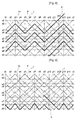
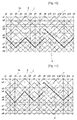
- FIGS. 2 through 14 are views illustrating consecutive processes of manufacturing the stent.
- a stent is formed of first and second members 1 and 3.
- FIGS. 2 through 7 are views illustrating a process, in which the cylindrical stent is formed of the first member on a manufacturing frame.
- FIGS. 8 through 14 are views illustrating a process, in which a fine mesh structure is formed of the second member.
- the fine mesh structure is formed on the cylindrical stent formed of the first member.
- the first and second members 1 and 3 may be formed of a wire member, which may be coated in order to be inserted into a lumen or a lesion of a human body for a medical use.
- the method of manufacturing the stent using a manufacturing frame J will be described in detail.
- the manufacturing frame J is cylindrical, and a plurality of pins P are disposed on a cylindrical surface on which the plurality of pins protrude in a radial direction.
- the gaps between the plurality of pins are same as each other, but the plurality of pins may be disposed with different gaps according to a design of the stent.
- It is preferable a plurality of holes are formed on the manufacturing frame J, and the plurality of pins are inserted into the plurality of holes.
- 9 rows of the plurality of pins (from top x1, x2, x3,..
- x9 hereinafter pin and point are same location, and a usage of pin and point is mingled for convenience
- 14 pins are disposed on the first row x1 and the last row x9. Gaps between the 14 pins in the radial direction of the manufacturing frame J are identical to each other.
- 7 pins are disposed on the rows from x2 to x8. The number of pins disposed on the manufacturing frame j is not limited to this embodiment, and the stent may be manufactured using different numbers of pins.
- Peaks and valleys are formed of the first member 1 successively from x1 to x9, in which the starting point is x1y5.
- the peaks and valleys of the first member are formed along the cylindrical surface of the manufacturing frame J, wherein a track of the first member 1 is bent zigzag. That is, referring to FIG. 2 , the track of the first member 1 passes the points x3y3, x1y1, x3y13, x1y11, x3y9, x1y7, x5y3, x3y1, x5y13, x3y11,.. x9y9, and x7y7.
- Peaks and valleys are formed of the first member 1 successively from x9 to x1 along the cylindrical surface of the manufacturing frame J, wherein a track of the first member 1 is bent zigzag. That is, the track of the first member 1 is continued to pass the points x7y7, x9y5, x7y3, x9y1, x7y13, x9y11, x7y9, x9y7, and x5y3.
- the first member 1 may be crossed and interlocked simultaneously to the preceding first member in order to keep connected status. It is preferable peaks and valleys are crossed and interlocked simultaneously when peaks and valleys meet each other, and hereinafter this description may be omitted sometimes.
- the track of the peaks and valleys of the first member 1 is continuously formed on the cylindrical surface of the manufacturing frame. That is, referring FIG. 4 , the track of the first member 1 passes continuously the points x5y3, x7y1, x5y13, x7y11, x5y9, x7y7, and x3y3 in order to form the stent. Also, referring FIG. 5 , the track of the first member 1 passes continuously the points x3y3, x5y1, x3y13, x5y11, x3y9, x5y7, and x1y3 in order to form the stent. In addition, referring FIG.
- the track of the first member 1 passes continuously the points x1y3, x3y1, s1y13, x3y11, x1y9, x3y7, and x1y5 (the starting point) in order to form the stent.
- the track of the first member 1 forms the peaks and valleys on the cylindrical surface of the manufacturing frame J starting from the starting point (xly5).
- the track of the first member 1 passes from the first row to the last row.
- the track of the first member 1 continuously passes from the last row to the first row, and the track of the first member 1 meets the preceding first member 1 at the starting point (xly5).
- peaks and valleys are crossed and interlocked simultaneously whenever peaks and valleys meet each other.
- a spirally twisted strut (1a) is formed around the preceding first member at the starting point x1y5.
- the strut (1a) increases an elastic force in radial and longitudinal directions, thereby reducing a longitudinal shrinkage when the stent is inserted. Therefore, the stent may be inserted easily, and the stent may keep a fixed status at the lesion with stability.
- FIGS. 8 through 14 are views illustrating process for reducing a mesh size of the stent formed of the first member 1 using the second member 3. That is, it is preferable the second member 3 starts from the point x1y12. The point x1y12 is a symmetrically opposite location of the starting point x1y5 of the first member 1. Also, it is preferable the second member 3 crosses about half of the meshes formed by the first member 1, when the cylindrical stent is formed of the second member 3. This will now be described more fully with reference to FIGS. 8 through 14 .
- Peaks and valleys are formed of the second member 3 starting from the point s1y12 along the cylindrical surface of the manufacturing frame J, wherein a track of the second member 3 is bent zigzag from x1 to x9 successively. At this point, it is preferable the second member 3 crosses about a half of the each mesh formed of the first member 1 in order to form meshes of half size.
- the track of the second member 3 passes the points x1yl1,x4y9,x2y7,x4y5,x2y3,x4y1,x2y13,x6y9,x4y7,x6y5,x4y3, .. x6y13, and x9y10.
- peaks and valleys are formed of the second member 3 along the cylindrical surface of the manufacturing frame J, wherein a track of the second member 3 is bent zigzag from x9 to x1 successively.
- the track of the second member 3 is continued to pass the points x9y10, x8y9, x9y8, x8y7, x9y6, x8y5, x9y4, x8y3, x9y8, x8y1, x9y14, x8y13, x9y12, and x6y9.
- the second member 3 may be crossed and interlocked simultaneously in order to keep connected status. It is preferable peaks and valleys are crossed and interlocked simultaneously whenever peaks and valleys meet each other.
- the peaks and valleys of the second member 3 are formed on the cylindrical surface of the manufacturing frame. That is, referring FIG. 10 , the track of the second member 3 passes continuously the points x6y9, x8y7, x6y5, x8y3, x6y1, x8y13, and x4y9 in order to form the stent. Also, referring to FIG. 11 , the track of the second member 3 further passes continuously the points x4y9, x6y7, x4y5, x6y3, x4y1, x6y13, and x2y9 in order to form the stent. In addition, referring to FIG.
- the track of the second member 3 further passes continuously the points x1y10, x2y9, x1y8, x2y7, x1y6, x2y5, x1y4, x2y3, x1y2, x2y1, x1y14, x2y13, and x1y12 (the starting point of the second member 3) in order to form the stent.
- the track of the second member 3 forms the peaks and valleys on the cylindrical surface of the manufacturing frame J starting from the starting point x1y12 (x1y12 is a symmetrically opposite point of the starting point of the first member on the cylindrical surface). At this point, the track of the second member 3 passes from the first row to the last row. After then the track of the second member 3 continuously passes from the last row to the first row, and the track of the second member 3 meets the preceding second member 3 at the starting point x1y12. It is preferable, according to the present invention, peaks and valleys are crossed and interlocked simultaneously when peaks and valleys meet each other.
- another spirally twisted strut (3a) is formed around the preceding second member at the starting point x1y12.
- the strut (3a) increases an elastic force in radial and longitudinal directions, thereby reducing the longitudinal shrinkage when the stent is inserted. Therefore, the stent may be inserted easily, and the stent may keep a fixed status at the lesion with stability.
- the struts (1a and 3a) are disposed as symmetric spirals.
- the processes for the second member are conducted after the processes for the first member 1 are completed. Accordingly, the first and second members 1 and 3 may not be interlocked each other simultaneously, and unprocessed part (the end part of the first and second members that may be wire members) of the first and second members 1 and 3 may not be damaged during the manufacturing processes. Therefore, a working efficiency is increased, and a quality of products may be improved. Specially, the manufacturing method of the present invention may form a finer mesh structure with an easy working process and thus the quality of the stent may be more improved.
- the first and second members 1 and 3 are crossed and interlocked each other when they meet each other. Accordingly, when the stent is constricted, the stent has a smaller diameter than a stent formed by the prior art in which peaks and valleys are continuously interlocked each other without crossing points. Therefore, according to the present invention, the stent may be inserted using an introducer having a smaller diameter.
- the stent may be used in a field of medical equipments. That is, the stent may be inserted into a lumen of a human body, or into a lesion of a blood vessel in order to maintain a passageway of the lumen, or the blood vessel.
Landscapes
- Health & Medical Sciences (AREA)
- Engineering & Computer Science (AREA)
- Biomedical Technology (AREA)
- Cardiology (AREA)
- Oral & Maxillofacial Surgery (AREA)
- Transplantation (AREA)
- Heart & Thoracic Surgery (AREA)
- Vascular Medicine (AREA)
- Life Sciences & Earth Sciences (AREA)
- Animal Behavior & Ethology (AREA)
- General Health & Medical Sciences (AREA)
- Public Health (AREA)
- Veterinary Medicine (AREA)
- Media Introduction/Drainage Providing Device (AREA)
- Prostheses (AREA)
Claims (6)
- Ein Verfahren zur Herstellung eines Stents, das Folgendes umfasst:Formen einer ersten zylindrischen Gitterstruktur durch Biegen eines ersten Gliedes (1) in eine Zickzackform mit Spitzen und Tälern, angeordnet in aufeinander folgenden Reihen (x1-x9), angeordnet in Längsrichtung des Stents, und an Punkten (y1-y14), die in Umfangsrichtung an den Reihen (x1-x7) liegen, und einer Vielzahl von Windungen, die um einen äußeren Umfang eines Produktionsrahmens (J) gewunden sind, so dass eine Bahn des ersten Gliedes (1) die Spitzen und die Täler bildet, ausgehend von einem Ausgangspunkt (x1y5) davon; undFormen einer zweiten zylindrischen Gitterstruktur durch Biegen eines zweiten Gliedes (3) in eine Zickzackform mit Spitzen und Tälern, angeordnet in aufeinander folgenden Reihen (x1-x9), angeordnet in Längsrichtung des Stents, und an Punkten (y1-y14), die in Umfangsrichtung an den Reihen (x1-x7) liegen, und einer Vielzahl von Windungen, die um einen äußeren Umfang des Herstellungsrahmens (J) gewunden sind, so dass eine Bahn des zweiten Gliedes (3) die Spitzen und die Täler bildet, ausgehend von einem Ausgangspunkt (x1y12) davon;wobei eine gebogene Bahn des zweiten Gliedes (3) eine gebogene Bahn des ersten Gliedes (1) kreuzt,dadurch gekennzeichnet, dass während der Formschrittedie Bahn des ersten Gliedes (1) von der ersten Reihe zur letzten Reihe und dann kontinuierlich von der letzten Reihe zur ersten Reihe geführt wird, wobei die Bahn des ersten Gliedes (1) auf das vorhergehende erste Glied (1) am Ausgangspunkt (x1y5) davon trifft;die Bahn des zweiten Gliedes (3) von der ersten Reihe zur letzten Reihe und dann kontinuierlich von der letzten Reihe zur ersten Reihe geführt wird, wobei die Bahn des zweiten Gliedes (3) auf das vorhergehende zweite Glied (3) am Ausgangspunkt (x1y12) davon trifft;undnachdem die erste zylindrische Gitterstruktur geformt wurde, Formen einer ersten Verstrebung (1a), die geformt wird durch spiralförmiges Drehen des ersten Gliedes am Ausgangspunkt (x1y5) des ersten Gliedes, wo ein distales Ende des ersten Gliedes (1) auf ein proximales Ende des ersten Gliedes (1) trifft; undnachdem die zweite zylindrische Gitterstruktur geformt wurde, Formen einer zweiten Verstrebung (3a), die geformt wird durch spiralförmiges Drehen des zweiten Gliedes am Ausgangspunkt (x1y12) des zweiten Gliedes, wo ein distales Ende des zweiten Gliedes (3) auf ein proximales Ende des zweiten Gliedes (3) trifft.
- Das Verfahren gemäß Anspruch 1, wobei die Spitzen und Täler verschiedener Windungen des ersten Gliedes (1) einander kreuzen und miteinander verblockt sind, wenn die Spitzen und Täler der verschiedenen Windungen des ersten Gliedes (1) während der Bildung der ersten zylindrischen Gitterstruktur aufeinander treffen.
- Das Verfahren gemäß Anspruch 1, wobei die Spitzen und Täler verschiedener Windungen des zweiten Gliedes (3) einander kreuzen und miteinander verblockt werden, wenn die Spitzen und Täler verschiedener Windungen des zweiten Gliedes (3) während der Bildung der zweiten zylindrischen Gitterstruktur aufeinander treffen.
- Ein Verfahren zur Herstellung eines Stents gemäß Anspruch 1, das Folgendes umfasst:Bereitstellen einer Vielzahl von Stiften (P) auf einer zylindrischen Oberfläche eines zylindrischen Produktionsrahmens (J) und Bestimmen eines (x1y5, x1y12y) aus einer Vielzahl von Stiften (P) als Ausgangspunkt;wobei die Formschritte Folgendes umfassen:Winden des ersten Gliedes (1) um den zylindrischen Produktionsrahmen vom Ausgangspunkt (x1y5) desselben bis zu einem Ende des zylindrischen Produktionsrahmens, während es in eine Zickzackform gebogen wird, um Spitzen und Täler mit Bezug auf die Stifte zu bilden, und eine Vielzahl von Windungen hat;Winden des ersten Gliedes um den zylindrischen Produktionsrahmen vom Ende des zylindrischen Produktionsrahmens (J) bis zum Ausgangspunkt des ersten Gliedes, während es in eine Zickzackform gebogen wird, um Spitzen und Täler mit Bezug auf die Stifte zu bilden, und eine Vielzahl von Windungen hat, wobei die Spitzen und Täler einander kreuzen und miteinander verblockt werden, wenn die Spitzen und Täler aufeinander treffen;Formen der Verstrebung (1a) durch spiralförmiges Verdrehen eines distalen Endabschnitts des ersten Gliedes (1) und eines proximalen Endabschnitts des ersten Gliedes (1), nachdem die Spitzen und Täler des ersten Gliedes (1) geformt wurden;Winden des zweiten Gliedes (3) um den zylindrischen Produktionsrahmen (J) von einem Ausgangspunkt (x1y12) desselben bis zu einem Ende des zylindrischen Produktionsrahmens, während es in eine Zickzackform gebogen wird, um Spitzen und Täler mit Bezug auf die Stifte (P) zu bilden, und eine Vielzahl von Windungen hat, wobei der Ausgangspunkt (x1y12) des zweiten Gliedes (3) an einer Stelle angeordnet ist, die dem Ausgangspunkt (x1y5) des ersten Gliedes (3) auf der Oberfläche des zylindrischen Produktionsrahmens (J) symmetrisch gegenüberliegt;Winden des zweiten Gliedes (3) um den zylindrischen Produktionsrahmen (J) vom Ende des zylindrischen Produktionsrahmens bis zum Ausgangspunkt (x1y12) des zweiten Gliedes, während es in eine Zickzackform gebogen wird, um Spitzen und Täler mit Bezug auf die Stifte zu bilden, und eine Vielzahl von Windungen hat, wobei die Spitzen und Täler einander kreuzen und miteinander verblockt werden, wenn die Spitzen und Täler aufeinander treffen; undFormen einer Verstrebung (3a) durch spiralförmiges Verdrehen eines distalen Endabschnitts des zweiten Gliedes (3) und eines proximalen Endabschnitts des zweiten Gliedes (3), nachdem die Spitzen und Täler des ersten Gliedes (1) geformt wurden.
- Ein Stent, der Folgendes umfasst:eine erste zylindrische Gitterstruktur, geformt durch Biegen eines ersten Gliedes (1) in eine Zickzackform mit Spitzen und Tälern, angeordnet in aufeinander folgenden Reihen (x1-x9), angeordnet in Längsrichtung des Stents und an Punkten (y1-y14), die in Umfangsrichtung an den Reihen (x1-x7) liegen, und eine Vielzahl von Windungen, gewunden, um die erste zylindrische Gitterstruktur zu bilden, wobei eine Bahn des ersten Gliedes (1) die Spitzen und die Täler bildet, ausgehend von einem Ausgangspunkt (x1y5) davon; undeine zweite zylindrische Gitterstruktur, geformt durch Biegen eines zweiten Gliedes (3) in eine Zickzackform mit Spitzen und Tälern, angeordnet in aufeinander folgenden Reihen (x1-x9), angeordnet in Längsrichtung des Stents und an Punkten (y1-y14), die in Umfangsrichtung an den Reihen (x1-x7) liegen, und eine Vielzahl von Windungen, gewunden, um die zweite zylindrische Gitterstruktur zu bilden, wobei eine Bahn des zweiten Gliedes (3) die Spitzen und die Täler bildet, ausgehend von einem Ausgangspunkt (x1y12) des zweiten Gliedes; wobei eine gebogene Bahn des zweiten Gliedes (3) eine gebogene Bahn des ersten Gliedes (1) kreuzt,dadurch gekennzeichnet, dassdie Bahn des ersten Gliedes (1) von der ersten Reihe zur letzten Reihe und dann kontinuierlich von der letzten Reihe zur ersten Reihe verläuft, wobei die Bahn des ersten Gliedes (1) am Ausgangspunkt (x1y5) des ersten Gliedes (3) auf das vorhergehende erste Glied (1) trifft;die Bahn des zweiten Gliedes (3) von der ersten Reihe zur letzten Reihe und dann kontinuierlich von der letzten Reihe zur ersten Reihe verläuft, wobei die Bahn des zweiten Gliedes (3) am Ausgangspunkt (x1y12) des zweiten Gliedes (3) auf das vorhergehende zweite Glied (3) trifft;die erste zylindrische Gitterstruktur eine erste Verstrebung (1a) einschließt, geformt durch spiralförmiges Verdrehen des ersten Gliedes am Ausgangspunkt (x1y5) des ersten Gliedes (3), wo ein distales Ende des ersten Gliedes (1) auf ein proximales Ende des ersten Gliedes (1) trifft; unddie zweite zylindrische Gitterstruktur eine zweite Verstrebung (3a) einschließt, geformt durch spiralförmiges Verdrehen des zweiten Gliedes am Ausgangspunkt (x1y12) des zweiten Gliedes (3), wo ein distales Ende des zweiten Gliedes (3) auf ein proximales Ende des zweiten Gliedes (3) trifft.
- Der Stent gemäß Anspruch 5, wobei die Spitzen und Täler der ersten und zweiten Glieder (1, 3) einander in Hakenform kreuzen und miteinander verblockt werden, wenn sie aufeinander treffen.
Applications Claiming Priority (2)
| Application Number | Priority Date | Filing Date | Title |
|---|---|---|---|
| KR1020050064359A KR100633020B1 (ko) | 2005-07-15 | 2005-07-15 | 스텐트 및 그의 제작 방법 |
| PCT/KR2006/002652 WO2007011122A1 (en) | 2005-07-15 | 2006-07-07 | Stent and method for manufacturing the same |
Publications (3)
| Publication Number | Publication Date |
|---|---|
| EP1903984A1 EP1903984A1 (de) | 2008-04-02 |
| EP1903984A4 EP1903984A4 (de) | 2014-11-19 |
| EP1903984B1 true EP1903984B1 (de) | 2016-10-19 |
Family
ID=37635561
Family Applications (1)
| Application Number | Title | Priority Date | Filing Date |
|---|---|---|---|
| EP06769196.4A Active EP1903984B1 (de) | 2005-07-15 | 2006-07-07 | Stent und verfahren zu seiner herstellung |
Country Status (6)
| Country | Link |
|---|---|
| US (2) | US20080167709A1 (de) |
| EP (1) | EP1903984B1 (de) |
| JP (1) | JP4764925B2 (de) |
| KR (1) | KR100633020B1 (de) |
| CN (1) | CN101184449B (de) |
| WO (1) | WO2007011122A1 (de) |
Families Citing this family (36)
| Publication number | Priority date | Publication date | Assignee | Title |
|---|---|---|---|---|
| US7018401B1 (en) | 1999-02-01 | 2006-03-28 | Board Of Regents, The University Of Texas System | Woven intravascular devices and methods for making the same and apparatus for delivery of the same |
| US6632241B1 (en) * | 2000-03-22 | 2003-10-14 | Endovascular Technologies, Inc. | Self-expanding, pseudo-braided intravascular device |
| US9545300B2 (en) * | 2004-12-22 | 2017-01-17 | W. L. Gore & Associates, Inc. | Filament-wound implantable devices |
| KR100633020B1 (ko) | 2005-07-15 | 2006-10-11 | 주식회사 스텐다드싸이텍 | 스텐트 및 그의 제작 방법 |
| WO2008051935A1 (en) | 2006-10-22 | 2008-05-02 | Idev Technologies, Inc. | Methods for securing strand ends and the resulting devices |
| KR100847432B1 (ko) * | 2007-03-14 | 2008-07-21 | 주식회사 에스앤지바이오텍 | 내강 확장용 스텐트 |
| US8151682B2 (en) | 2009-01-26 | 2012-04-10 | Boston Scientific Scimed, Inc. | Atraumatic stent and method and apparatus for making the same |
| JP5801037B2 (ja) * | 2010-05-25 | 2015-10-28 | アクセスポイント テクノロジーズ有限会社 | ステント |
| KR101176014B1 (ko) | 2010-08-06 | 2012-08-24 | (주) 더아이엔지메디칼 | 인체 내강 확장용 스텐트 및 이를 포함하는 스텐트삽입장치 |
| KR101330825B1 (ko) * | 2011-01-14 | 2013-11-15 | 신경민 | 굽힘 특성이 양호한 스텐트의 제조방법과 그 스텐트 |
| CN102134781B (zh) * | 2011-03-16 | 2013-09-25 | 中材科技股份有限公司 | 整体管状织物结构 |
| CN102973341B (zh) * | 2012-11-08 | 2015-06-17 | 先健科技(深圳)有限公司 | 一种编织的自膨式管腔支架及其制作方法 |
| EP2983625B1 (de) * | 2013-04-13 | 2024-02-14 | Solinas Medical, Inc. | Selbstschliessende vorrichtungen sowie einrichtung und verfahren zur herstellung und ausgabe davon |
| JP5939642B2 (ja) * | 2013-05-02 | 2016-06-22 | 日本ライフライン株式会社 | ステント |
| KR101654861B1 (ko) * | 2014-08-27 | 2016-09-06 | 주식회사 비씨엠 | 스텐트와 그 스텐트 제조방법 |
| KR101488972B1 (ko) * | 2014-09-12 | 2015-02-02 | (주)시지바이오 | 스텐트 및 이 스텐트의 제조방법 |
| KR101696810B1 (ko) * | 2015-02-04 | 2017-02-01 | 주식회사 엠아이텍 | 연결용 스텐트 및 그의 제조방법 |
| KR101728319B1 (ko) * | 2015-04-15 | 2017-04-19 | 주식회사 엠아이텍 | 스텐트 제조방법 |
| JP6470150B2 (ja) | 2015-09-03 | 2019-02-13 | 日本ライフライン株式会社 | ステントおよび医療機器 |
| US20170119556A1 (en) * | 2015-10-30 | 2017-05-04 | Boston Scientific Scimed, Inc. | Implantable medical device with bonding region |
| US11370590B2 (en) | 2015-11-18 | 2022-06-28 | Selenium Medical | Packaging, preferably medical, and corresponding assembly of packagings |
| KR101785042B1 (ko) | 2016-02-15 | 2017-10-12 | (주) 태웅메디칼 | 형상기억합금 와이어를 이용한 스텐트의 제조방법과 이에 의해 제조한 스텐트 및 이를 제조하기 위한 지그 |
| JP6470219B2 (ja) * | 2016-03-25 | 2019-02-13 | 日本ライフライン株式会社 | ステントおよび医療機器 |
| KR101811634B1 (ko) | 2016-04-14 | 2017-12-27 | 김정권 | 스텐트 제조방법 |
| JP6072973B1 (ja) * | 2016-10-21 | 2017-02-01 | 株式会社北村製作所 | テンポラリーステントの製造方法 |
| KR101910952B1 (ko) * | 2016-10-28 | 2018-10-23 | 주식회사 넥스트바이오메디컬 | 압착 후 스텐트 지름을 산출하는 방법 |
| CN108498218A (zh) * | 2018-05-10 | 2018-09-07 | 禾木(中国)生物工程有限公司 | 血管支架 |
| JP6985526B2 (ja) | 2018-09-21 | 2021-12-22 | 日本ライフライン株式会社 | ステントおよび医療機器 |
| CN111970997B (zh) | 2018-09-26 | 2024-09-10 | 日本来富恩株式会社 | 支架和支架移植物 |
| US20200138609A1 (en) * | 2018-11-02 | 2020-05-07 | Microvention, Inc. | Woven Stent With Improved Deployment Characteristics |
| CN111118729B (zh) * | 2020-01-10 | 2021-06-01 | 江苏唯德康医疗科技有限公司 | 一种支架编织方法及使用该方法制成的支架 |
| CN111803253B (zh) * | 2020-07-20 | 2023-05-30 | 河南驼人贝斯特医疗器械有限公司 | 一种自膨胀合金支架及其制造方法 |
| WO2022181661A1 (ja) * | 2021-02-26 | 2022-09-01 | Sbカワスミ株式会社 | ステント |
| CN115844606A (zh) * | 2021-09-24 | 2023-03-28 | 微创优通医疗科技(嘉兴)有限公司 | 用于肠道的支架及其编织方法 |
| CN114767202B (zh) * | 2022-04-24 | 2023-03-24 | 惠州市顺美医疗科技有限公司 | 一种颅内密网支架及其制备方法 |
| CN115553972B (zh) * | 2022-10-19 | 2023-10-20 | 常州乐奥医疗科技股份有限公司 | 一种胆道支架制造方法及胆道支架 |
Family Cites Families (33)
| Publication number | Priority date | Publication date | Assignee | Title |
|---|---|---|---|---|
| SE453258B (sv) * | 1986-04-21 | 1988-01-25 | Medinvent Sa | Elastisk, sjelvexpanderande protes samt forfarande for dess framstellning |
| US5540712A (en) | 1992-05-01 | 1996-07-30 | Nitinol Medical Technologies, Inc. | Stent and method and apparatus for forming and delivering the same |
| CA2141208C (en) * | 1992-08-06 | 2004-10-26 | Zaza A. Kavteladze | A prosthetic device for sustaining a blood-vessel or hollow organ lumen |
| KR970004845Y1 (ko) * | 1993-09-27 | 1997-05-21 | 주식회사 수호메디테크 | 내강확장용 의료용구 |
| RU2089131C1 (ru) * | 1993-12-28 | 1997-09-10 | Сергей Апполонович Пульнев | Стент |
| US6165210A (en) * | 1994-04-01 | 2000-12-26 | Gore Enterprise Holdings, Inc. | Self-expandable helical intravascular stent and stent-graft |
| EP0754016B1 (de) | 1994-04-01 | 2003-07-09 | Prograft Medical, Inc. | Selbstausdehnbarer stent und stent-graft transplantat |
| CA2189006A1 (en) * | 1994-04-29 | 1995-11-09 | Boston Scientific Corporation | Medical prosthetic stent and method of manufacture |
| DE4424242A1 (de) * | 1994-07-09 | 1996-01-11 | Ernst Peter Prof Dr M Strecker | In den Körper eines Patienten perkutan implantierbare Endoprothese |
| US6015429A (en) * | 1994-09-08 | 2000-01-18 | Gore Enterprise Holdings, Inc. | Procedures for introducing stents and stent-grafts |
| CN1118271C (zh) * | 1995-03-27 | 2003-08-20 | 守镐Medi-Tech株式会社 | 用于扩张腔的斯坦特固定模 |
| RU2157146C2 (ru) * | 1995-06-13 | 2000-10-10 | ВИЛЬЯМ КУК Европа, A/S | Устройство для имплантации в сосудах и полых органах (его варианты) |
| JP2900988B2 (ja) * | 1995-09-29 | 1999-06-02 | 株式会社多賀製作所 | 線材の折り曲げ装置 |
| GB9522332D0 (en) * | 1995-11-01 | 1996-01-03 | Biocompatibles Ltd | Braided stent |
| US6241757B1 (en) * | 1997-02-04 | 2001-06-05 | Solco Surgical Instrument Co., Ltd. | Stent for expanding body's lumen |
| EP0884029B1 (de) * | 1997-06-13 | 2004-12-22 | Gary J. Becker | Expandierbare intraluminale Endoprothese |
| JPH1142284A (ja) * | 1997-07-25 | 1999-02-16 | Ube Ind Ltd | ステント付き人工血管 |
| WO1999044535A1 (en) * | 1998-03-05 | 1999-09-10 | Boston Scientific Limited | Intraluminal stent |
| JP4621849B2 (ja) * | 2000-07-31 | 2011-01-26 | マニー株式会社 | ステントの製造方法 |
| US7018401B1 (en) * | 1999-02-01 | 2006-03-28 | Board Of Regents, The University Of Texas System | Woven intravascular devices and methods for making the same and apparatus for delivery of the same |
| KR100319663B1 (ko) * | 1999-12-07 | 2002-01-05 | 이길환 | 스텐트 |
| BE1013757A6 (fr) * | 2000-12-12 | 2002-07-02 | Frid Noureddine | Endoprothese luminale modulable. |
| KR100393548B1 (ko) * | 2001-06-05 | 2003-08-02 | 주식회사 엠아이텍 | 의료용 스텐트 |
| CN2518525Y (zh) * | 2001-09-28 | 2002-10-30 | 上海形状记忆合金材料有限公司 | 一种新型血管病损支架 |
| US20030074051A1 (en) * | 2001-10-16 | 2003-04-17 | Kirsten Freislinger Luehrs | Flexible stent |
| FR2847155B1 (fr) | 2002-11-20 | 2005-08-05 | Younes Boudjemline | Procede de fabrication d'un implant medical a structure ajouree et implant obtenu par ce procede |
| US20040186549A1 (en) * | 2003-03-19 | 2004-09-23 | Swaminathan Jayaraman | Braided stent with looped ends and method for making same |
| KR100561713B1 (ko) * | 2003-05-23 | 2006-03-20 | (주) 태웅메디칼 | 가변상태 유지형 스텐트의 제조방법과 이에 의해 제조된가변상태 유지형 스텐트 |
| WO2004105853A1 (en) * | 2003-06-02 | 2004-12-09 | S & G Biotech, Inc. | A cylindrical stent |
| US7445631B2 (en) * | 2003-12-23 | 2008-11-04 | Sadra Medical, Inc. | Methods and apparatus for endovascularly replacing a patient's heart valve |
| US9545300B2 (en) * | 2004-12-22 | 2017-01-17 | W. L. Gore & Associates, Inc. | Filament-wound implantable devices |
| KR100633020B1 (ko) | 2005-07-15 | 2006-10-11 | 주식회사 스텐다드싸이텍 | 스텐트 및 그의 제작 방법 |
| US20070219618A1 (en) * | 2006-03-17 | 2007-09-20 | Cully Edward H | Endoprosthesis having multiple helically wound flexible framework elements |
-
2005
- 2005-07-15 KR KR1020050064359A patent/KR100633020B1/ko not_active Expired - Lifetime
-
2006
- 2006-07-07 CN CN2006800188457A patent/CN101184449B/zh active Active
- 2006-07-07 EP EP06769196.4A patent/EP1903984B1/de active Active
- 2006-07-07 WO PCT/KR2006/002652 patent/WO2007011122A1/en not_active Ceased
- 2006-07-07 US US11/914,490 patent/US20080167709A1/en not_active Abandoned
- 2006-07-07 JP JP2008521301A patent/JP4764925B2/ja active Active
-
2011
- 2011-01-25 US US13/012,946 patent/US8210084B2/en active Active
Also Published As
| Publication number | Publication date |
|---|---|
| KR100633020B1 (ko) | 2006-10-11 |
| US20080167709A1 (en) | 2008-07-10 |
| US8210084B2 (en) | 2012-07-03 |
| US20110125250A1 (en) | 2011-05-26 |
| CN101184449B (zh) | 2010-06-16 |
| CN101184449A (zh) | 2008-05-21 |
| EP1903984A1 (de) | 2008-04-02 |
| JP2009501049A (ja) | 2009-01-15 |
| JP4764925B2 (ja) | 2011-09-07 |
| WO2007011122A1 (en) | 2007-01-25 |
| EP1903984A4 (de) | 2014-11-19 |
Similar Documents
| Publication | Publication Date | Title |
|---|---|---|
| US20110125250A1 (en) | Stent and Method for Manufacturing the Same | |
| JP2975584B2 (ja) | 体腔拡張用ステント | |
| US5749919A (en) | Resilient prosthesis for widening a channel, particularly a blood vessel, and method for making same | |
| CN103784222B (zh) | 一种自膨式支架 | |
| US20030105515A1 (en) | Stent designs | |
| CN1310599A (zh) | 可膨胀的固定模及其使用方法 | |
| CN104768502B (zh) | 具有正交端部的螺旋支架以及形成支架的方法 | |
| JP2007516771A (ja) | 湾曲部で展開されるステント | |
| EP1813224B1 (de) | Selbstexpandierbarer Stent aus einer Formgedächtnislegierung und Verfahren zu seiner Herstellung | |
| WO1999044535A1 (en) | Intraluminal stent | |
| CN219074239U (zh) | 一种胆道支架制造夹具 | |
| EP1235535B1 (de) | Stent | |
| KR100320239B1 (ko) | 내강확장용스텐트와그제조방법 | |
| US20230190498A1 (en) | Stent with shaped wires | |
| KR102438975B1 (ko) | 이중 구조 스텐트 및 그 제조 방법 | |
| KR100240832B1 (ko) | 인체내의 내강 확장용 스텐트와 그 제조 방법 | |
| CN115889619A (zh) | 一种胆道支架制造夹具及胆道支架制造方法 | |
| KR100548781B1 (ko) | 원통형 스텐트 | |
| KR100329203B1 (ko) | 스텐트 | |
| KR100190755B1 (ko) | 내강 확장용 의료용구 및 그 제조방법 | |
| KR19990065081A (ko) | 내강 확장용 스텐트 | |
| KR100548782B1 (ko) | 원통형 스텐트 | |
| JP6985526B2 (ja) | ステントおよび医療機器 | |
| KR20020072698A (ko) | 복수조합으로 구성된 내강확장용 스텐트 |
Legal Events
| Date | Code | Title | Description |
|---|---|---|---|
| PUAI | Public reference made under article 153(3) epc to a published international application that has entered the european phase |
Free format text: ORIGINAL CODE: 0009012 |
|
| 17P | Request for examination filed |
Effective date: 20071108 |
|
| AK | Designated contracting states |
Kind code of ref document: A1 Designated state(s): AT BE BG CH CY CZ DE DK EE ES FI FR GB GR HU IE IS IT LI LT LU LV MC NL PL PT RO SE SI SK TR |
|
| DAX | Request for extension of the european patent (deleted) | ||
| DAX | Request for extension of the european patent (deleted) | ||
| REG | Reference to a national code |
Ref country code: DE Ref legal event code: R079 Ref document number: 602006050632 Country of ref document: DE Free format text: PREVIOUS MAIN CLASS: A61F0002060000 Ipc: A61F0002900000 |
|
| A4 | Supplementary search report drawn up and despatched |
Effective date: 20141020 |
|
| RIC1 | Information provided on ipc code assigned before grant |
Ipc: A61F 2/90 20130101AFI20141014BHEP |
|
| 17Q | First examination report despatched |
Effective date: 20150826 |
|
| GRAP | Despatch of communication of intention to grant a patent |
Free format text: ORIGINAL CODE: EPIDOSNIGR1 |
|
| INTG | Intention to grant announced |
Effective date: 20160506 |
|
| GRAS | Grant fee paid |
Free format text: ORIGINAL CODE: EPIDOSNIGR3 |
|
| GRAA | (expected) grant |
Free format text: ORIGINAL CODE: 0009210 |
|
| AK | Designated contracting states |
Kind code of ref document: B1 Designated state(s): AT BE BG CH CY CZ DE DK EE ES FI FR GB GR HU IE IS IT LI LT LU LV MC NL PL PT RO SE SI SK TR |
|
| REG | Reference to a national code |
Ref country code: GB Ref legal event code: FG4D |
|
| REG | Reference to a national code |
Ref country code: CH Ref legal event code: EP |
|
| REG | Reference to a national code |
Ref country code: AT Ref legal event code: REF Ref document number: 837677 Country of ref document: AT Kind code of ref document: T Effective date: 20161115 |
|
| REG | Reference to a national code |
Ref country code: IE Ref legal event code: FG4D |
|
| REG | Reference to a national code |
Ref country code: DE Ref legal event code: R096 Ref document number: 602006050632 Country of ref document: DE |
|
| REG | Reference to a national code |
Ref country code: NL Ref legal event code: MP Effective date: 20161019 |
|
| REG | Reference to a national code |
Ref country code: LT Ref legal event code: MG4D |
|
| PG25 | Lapsed in a contracting state [announced via postgrant information from national office to epo] |
Ref country code: LV Free format text: LAPSE BECAUSE OF FAILURE TO SUBMIT A TRANSLATION OF THE DESCRIPTION OR TO PAY THE FEE WITHIN THE PRESCRIBED TIME-LIMIT Effective date: 20161019 |
|
| REG | Reference to a national code |
Ref country code: AT Ref legal event code: MK05 Ref document number: 837677 Country of ref document: AT Kind code of ref document: T Effective date: 20161019 |
|
| PG25 | Lapsed in a contracting state [announced via postgrant information from national office to epo] |
Ref country code: LT Free format text: LAPSE BECAUSE OF FAILURE TO SUBMIT A TRANSLATION OF THE DESCRIPTION OR TO PAY THE FEE WITHIN THE PRESCRIBED TIME-LIMIT Effective date: 20161019 Ref country code: GR Free format text: LAPSE BECAUSE OF FAILURE TO SUBMIT A TRANSLATION OF THE DESCRIPTION OR TO PAY THE FEE WITHIN THE PRESCRIBED TIME-LIMIT Effective date: 20170120 Ref country code: SE Free format text: LAPSE BECAUSE OF FAILURE TO SUBMIT A TRANSLATION OF THE DESCRIPTION OR TO PAY THE FEE WITHIN THE PRESCRIBED TIME-LIMIT Effective date: 20161019 |
|
| PG25 | Lapsed in a contracting state [announced via postgrant information from national office to epo] |
Ref country code: PL Free format text: LAPSE BECAUSE OF FAILURE TO SUBMIT A TRANSLATION OF THE DESCRIPTION OR TO PAY THE FEE WITHIN THE PRESCRIBED TIME-LIMIT Effective date: 20161019 Ref country code: IS Free format text: LAPSE BECAUSE OF FAILURE TO SUBMIT A TRANSLATION OF THE DESCRIPTION OR TO PAY THE FEE WITHIN THE PRESCRIBED TIME-LIMIT Effective date: 20170219 Ref country code: FI Free format text: LAPSE BECAUSE OF FAILURE TO SUBMIT A TRANSLATION OF THE DESCRIPTION OR TO PAY THE FEE WITHIN THE PRESCRIBED TIME-LIMIT Effective date: 20161019 Ref country code: PT Free format text: LAPSE BECAUSE OF FAILURE TO SUBMIT A TRANSLATION OF THE DESCRIPTION OR TO PAY THE FEE WITHIN THE PRESCRIBED TIME-LIMIT Effective date: 20170220 Ref country code: AT Free format text: LAPSE BECAUSE OF FAILURE TO SUBMIT A TRANSLATION OF THE DESCRIPTION OR TO PAY THE FEE WITHIN THE PRESCRIBED TIME-LIMIT Effective date: 20161019 Ref country code: ES Free format text: LAPSE BECAUSE OF FAILURE TO SUBMIT A TRANSLATION OF THE DESCRIPTION OR TO PAY THE FEE WITHIN THE PRESCRIBED TIME-LIMIT Effective date: 20161019 Ref country code: NL Free format text: LAPSE BECAUSE OF FAILURE TO SUBMIT A TRANSLATION OF THE DESCRIPTION OR TO PAY THE FEE WITHIN THE PRESCRIBED TIME-LIMIT Effective date: 20161019 Ref country code: BE Free format text: LAPSE BECAUSE OF FAILURE TO SUBMIT A TRANSLATION OF THE DESCRIPTION OR TO PAY THE FEE WITHIN THE PRESCRIBED TIME-LIMIT Effective date: 20161019 |
|
| REG | Reference to a national code |
Ref country code: FR Ref legal event code: PLFP Year of fee payment: 12 |
|
| REG | Reference to a national code |
Ref country code: DE Ref legal event code: R097 Ref document number: 602006050632 Country of ref document: DE |
|
| PG25 | Lapsed in a contracting state [announced via postgrant information from national office to epo] |
Ref country code: EE Free format text: LAPSE BECAUSE OF FAILURE TO SUBMIT A TRANSLATION OF THE DESCRIPTION OR TO PAY THE FEE WITHIN THE PRESCRIBED TIME-LIMIT Effective date: 20161019 Ref country code: SK Free format text: LAPSE BECAUSE OF FAILURE TO SUBMIT A TRANSLATION OF THE DESCRIPTION OR TO PAY THE FEE WITHIN THE PRESCRIBED TIME-LIMIT Effective date: 20161019 Ref country code: DK Free format text: LAPSE BECAUSE OF FAILURE TO SUBMIT A TRANSLATION OF THE DESCRIPTION OR TO PAY THE FEE WITHIN THE PRESCRIBED TIME-LIMIT Effective date: 20161019 Ref country code: CZ Free format text: LAPSE BECAUSE OF FAILURE TO SUBMIT A TRANSLATION OF THE DESCRIPTION OR TO PAY THE FEE WITHIN THE PRESCRIBED TIME-LIMIT Effective date: 20161019 Ref country code: RO Free format text: LAPSE BECAUSE OF FAILURE TO SUBMIT A TRANSLATION OF THE DESCRIPTION OR TO PAY THE FEE WITHIN THE PRESCRIBED TIME-LIMIT Effective date: 20161019 |
|
| PLBE | No opposition filed within time limit |
Free format text: ORIGINAL CODE: 0009261 |
|
| STAA | Information on the status of an ep patent application or granted ep patent |
Free format text: STATUS: NO OPPOSITION FILED WITHIN TIME LIMIT |
|
| PG25 | Lapsed in a contracting state [announced via postgrant information from national office to epo] |
Ref country code: BG Free format text: LAPSE BECAUSE OF FAILURE TO SUBMIT A TRANSLATION OF THE DESCRIPTION OR TO PAY THE FEE WITHIN THE PRESCRIBED TIME-LIMIT Effective date: 20170119 |
|
| 26N | No opposition filed |
Effective date: 20170720 |
|
| PG25 | Lapsed in a contracting state [announced via postgrant information from national office to epo] |
Ref country code: SI Free format text: LAPSE BECAUSE OF FAILURE TO SUBMIT A TRANSLATION OF THE DESCRIPTION OR TO PAY THE FEE WITHIN THE PRESCRIBED TIME-LIMIT Effective date: 20161019 |
|
| REG | Reference to a national code |
Ref country code: CH Ref legal event code: PL |
|
| REG | Reference to a national code |
Ref country code: IE Ref legal event code: MM4A |
|
| PG25 | Lapsed in a contracting state [announced via postgrant information from national office to epo] |
Ref country code: CH Free format text: LAPSE BECAUSE OF NON-PAYMENT OF DUE FEES Effective date: 20170731 Ref country code: IE Free format text: LAPSE BECAUSE OF NON-PAYMENT OF DUE FEES Effective date: 20170707 Ref country code: LI Free format text: LAPSE BECAUSE OF NON-PAYMENT OF DUE FEES Effective date: 20170731 |
|
| PG25 | Lapsed in a contracting state [announced via postgrant information from national office to epo] |
Ref country code: LU Free format text: LAPSE BECAUSE OF NON-PAYMENT OF DUE FEES Effective date: 20170707 |
|
| REG | Reference to a national code |
Ref country code: FR Ref legal event code: PLFP Year of fee payment: 13 |
|
| PG25 | Lapsed in a contracting state [announced via postgrant information from national office to epo] |
Ref country code: HU Free format text: LAPSE BECAUSE OF FAILURE TO SUBMIT A TRANSLATION OF THE DESCRIPTION OR TO PAY THE FEE WITHIN THE PRESCRIBED TIME-LIMIT; INVALID AB INITIO Effective date: 20060707 Ref country code: MC Free format text: LAPSE BECAUSE OF FAILURE TO SUBMIT A TRANSLATION OF THE DESCRIPTION OR TO PAY THE FEE WITHIN THE PRESCRIBED TIME-LIMIT Effective date: 20161019 |
|
| PG25 | Lapsed in a contracting state [announced via postgrant information from national office to epo] |
Ref country code: CY Free format text: LAPSE BECAUSE OF NON-PAYMENT OF DUE FEES Effective date: 20161019 |
|
| PG25 | Lapsed in a contracting state [announced via postgrant information from national office to epo] |
Ref country code: TR Free format text: LAPSE BECAUSE OF FAILURE TO SUBMIT A TRANSLATION OF THE DESCRIPTION OR TO PAY THE FEE WITHIN THE PRESCRIBED TIME-LIMIT Effective date: 20161019 |
|
| REG | Reference to a national code |
Ref country code: DE Ref legal event code: R082 Ref document number: 602006050632 Country of ref document: DE Representative=s name: SCHIEBER - FARAGO PATENTANWAELTE, DE Ref country code: DE Ref legal event code: R082 Ref document number: 602006050632 Country of ref document: DE Representative=s name: FARAGO PATENTANWALTSGESELLSCHAFT MBH, DE Ref country code: DE Ref legal event code: R082 Ref document number: 602006050632 Country of ref document: DE Representative=s name: WUESTHOFF & WUESTHOFF PATENTANWAELTE UND RECHT, DE Ref country code: DE Ref legal event code: R082 Ref document number: 602006050632 Country of ref document: DE Representative=s name: WUESTHOFF & WUESTHOFF, PATENTANWAELTE PARTG MB, DE |
|
| REG | Reference to a national code |
Ref country code: DE Ref legal event code: R082 Ref document number: 602006050632 Country of ref document: DE Representative=s name: SCHIEBER - FARAGO PATENTANWAELTE, DE Ref country code: DE Ref legal event code: R082 Ref document number: 602006050632 Country of ref document: DE Representative=s name: WUESTHOFF & WUESTHOFF PATENTANWAELTE UND RECHT, DE Ref country code: DE Ref legal event code: R082 Ref document number: 602006050632 Country of ref document: DE Representative=s name: WUESTHOFF & WUESTHOFF, PATENTANWAELTE PARTG MB, DE |
|
| REG | Reference to a national code |
Ref country code: DE Ref legal event code: R082 Ref document number: 602006050632 Country of ref document: DE Representative=s name: WUESTHOFF & WUESTHOFF PATENTANWAELTE UND RECHT, DE Ref country code: DE Ref legal event code: R082 Ref document number: 602006050632 Country of ref document: DE Representative=s name: WUESTHOFF & WUESTHOFF, PATENTANWAELTE PARTG MB, DE |
|
| PGFP | Annual fee paid to national office [announced via postgrant information from national office to epo] |
Ref country code: DE Payment date: 20250722 Year of fee payment: 20 |
|
| PGFP | Annual fee paid to national office [announced via postgrant information from national office to epo] |
Ref country code: IT Payment date: 20250728 Year of fee payment: 20 |
|
| PGFP | Annual fee paid to national office [announced via postgrant information from national office to epo] |
Ref country code: GB Payment date: 20250701 Year of fee payment: 20 |
|
| PGFP | Annual fee paid to national office [announced via postgrant information from national office to epo] |
Ref country code: FR Payment date: 20250703 Year of fee payment: 20 |