EP1904881B1 - Dispositif de distribution de fibres optiques - Google Patents
Dispositif de distribution de fibres optiques Download PDFInfo
- Publication number
- EP1904881B1 EP1904881B1 EP06762411A EP06762411A EP1904881B1 EP 1904881 B1 EP1904881 B1 EP 1904881B1 EP 06762411 A EP06762411 A EP 06762411A EP 06762411 A EP06762411 A EP 06762411A EP 1904881 B1 EP1904881 B1 EP 1904881B1
- Authority
- EP
- European Patent Office
- Prior art keywords
- optical waveguide
- functional area
- optical waveguides
- cable
- distribution panel
- Prior art date
- Legal status (The legal status is an assumption and is not a legal conclusion. Google has not performed a legal analysis and makes no representation as to the accuracy of the status listed.)
- Not-in-force
Links
- 239000013307 optical fiber Substances 0.000 title description 22
- 239000000835 fiber Substances 0.000 claims abstract description 26
- 230000003287 optical effect Effects 0.000 claims description 81
- 230000008878 coupling Effects 0.000 claims description 12
- 238000010168 coupling process Methods 0.000 claims description 12
- 238000005859 coupling reaction Methods 0.000 claims description 12
- 239000004033 plastic Substances 0.000 claims description 7
- 238000005452 bending Methods 0.000 claims description 3
- 229920000271 Kevlar® Polymers 0.000 claims 1
- 239000004761 kevlar Substances 0.000 claims 1
- 238000002347 injection Methods 0.000 description 4
- 239000007924 injection Substances 0.000 description 4
- 230000001419 dependent effect Effects 0.000 description 1
- 238000009434 installation Methods 0.000 description 1
Images

Classifications
-
- G—PHYSICS
- G02—OPTICS
- G02B—OPTICAL ELEMENTS, SYSTEMS OR APPARATUS
- G02B6/00—Light guides; Structural details of arrangements comprising light guides and other optical elements, e.g. couplings
- G02B6/44—Mechanical structures for providing tensile strength and external protection for fibres, e.g. optical transmission cables
- G02B6/4439—Auxiliary devices
- G02B6/444—Systems or boxes with surplus lengths
- G02B6/4453—Cassettes
Definitions
- the invention relates to an optical waveguide distribution device according to the preamble of claim 1.
- optical waveguide distribution device shown there serves in particular for the handling of optical fiber cables pre-assembled with plugs, such as patchcords or pigtails, wherein the optical waveguide distribution device shown there has a distributor field mounted or stored in a housing in a drawer-like manner Guide elements for optical fibers, couplings for connectors of prefabricated optical fibers, Zugabfangept for introduced into the distribution panel optical fiber cables and shelves for splices of optical fibers spliced together, the above elements or components are all designed as individual parts and connected to a support member of the distribution panel.
- the present invention is based on the problem to provide a novel optical waveguide distribution device.
- optical waveguide distribution device having the features of claim 1.
- the prefabricated optical waveguides and the optical waveguides introduced via the or each optical waveguide cable are guided without crossing within the distributor field.
- Fig. 1 shows a preferred embodiment of an optical waveguide distribution device 10 according to the invention in a perspective plan view, wherein the optical waveguide distribution device 10 comprises a distribution panel 11 which can be mounted and stored on holding elements or so-called bracket 12 on a frame, for example a distribution cabinet drawer-like.
- the distributor field 11 has a bottom wall 13 and four side walls 14, 15, 16 and 17, wherein the side wall 14 forms a front wall of the distributor field 11 and the side wall 15 forms a rear wall of the distributor field 11.
- the brackets 12 engage the side walls 16 and 17 of the distribution panel 11, wherein a translational relative movement between the distributor panel 11 and the brackets 12 for the drawer-like guide of the same is possible.
- FIG. 1 can be removed, 11 recesses or openings 18 are integrated into which formed as a front wall side wall 14 of the distribution panel 11, in which not shown couplings can be used or not engaged for non-illustrated plug. It should be noted at this point that such couplings can also be an integral part of the front wall 14 of the distribution panel 11.
- the distribution panel 11 of in Fig. 1 illustrated optical waveguide distribution device 10 is primarily the handling or storage of splices, which are formed between one-sided pre-assembled with plugs optical fibers and an optical fiber cable into the distribution panel 11 introduced optical fibers. Fiber optic cables prefabricated on one side with plugs are also referred to as pigtails.
- the splices between the prefabricated optical waveguides and the optical waveguides introduced into the distributor field 11 via an optical fiber cable are accommodated in trays 19 for the splices, the trays 19 being an integral part of the distributor field 11 embodied as a plastic injection molded part.
- the plug-free ends of the optical waveguides which are prefabricated on one side with plugs, can be fed to the shelves 19 via guide elements 20 while maintaining permissible minimum bending radii for the optical waveguides.
- the prefabricated with plugs ends of the prefabricated optical waveguides via guides 21 which are arranged adjacent to the front wall 14 of the distribution panel 11, while maintaining permissible Indeedbiegeradien the non-illustrated Couplings for the plug fed, the non-illustrated couplings find in the openings 18 of the front wall 14 recording.
- further guide elements 22 are positioned for the prefabricated optical waveguides, which form an excess length memory 23 for the prefabricated optical waveguides.
- At least one lightwave cable with optical waveguides guided therein is insertable, namely via an opening 24 integrated into the rear wall 15 of the distributor field 11.
- the distribution field 11 has tension clamps 25 for the optical waveguide cable for clamping the tension of the optical waveguide cable inserted into the distributor field 11 respective optical waveguide cables introduced into the distribution panel 11 optical fibers via guide elements 26 the trays 19 for the splices can be supplied while maintaining permissible minimum bending radii for the optical waveguide.
- Further guide elements 27 for the optical waveguides introduced into the distributor field 11 via an optical waveguide cable form an excess length memory 28 for the same.
- the trays 19 for splices between the prefabricated optical waveguides and the optical waveguides introduced into the distributor field 11 via an optical waveguide are an integral part of the distributor field 11 formed as a plastic injection molded part.
- the guide elements 20, 21, 22, 26, 27 and Thus, the excess length memory 23, 28 and the Zugabfangept 25 are an integral part of the distributor field 11 formed as a plastic injection molded part.
- the non-illustrated couplings for the connector of the prefabricated optical waveguides which in the embodiment shown record in the recesses 18 of the front wall 14 of the distribution box 11, an integral part of as a plastic injection molded part running distribution panel 11th
- Fig. 1 can be removed, the Zugabfangitch 25, the shelves 19 and the guide elements 20, 21, 22, 26, 27 are positioned in the distribution panel 11 such that the distribution panel 11 at least three spatially from each other having separate functional areas 29, 30 and 31.
- a first functional area 29 serves for the introduction and traction of at least one fiber-optic cable into the distributor field 11 and accordingly comprises the tension clamps 25.
- a second functional area 30 serves to guide the prefabricated optical waveguides to the non-illustrated couplings for the connectors thereof and accordingly comprises the guide elements 21.
- a third functional area 31 serves to guide the prefabricated optical waveguides as well as the optical waveguides introduced into the distributor field 11 via the or each optical waveguide cable in the region of the splices and the splice tray 19, and accordingly comprises the shelves 19, the guide elements 20, 22, 26 and 27 and thus also the excess length memory 23 and 28.
- Fig. 1 can be removed, the three functional areas 29, 30 and 31 arranged spatially separated from each other in the distribution panel 11, that the pre-assembled optical waveguides and introduced via the or each fiber optic cable into the distribution panel 11 optical fiber can be performed without crossing within the distribution box 11.
- the second functional area 30 is positioned adjacent to the front wall 14 and thus adjacent to a front side of the distribution panel 11.
- the first functional region 29 and the third functional region 31 are each arranged adjacent to the rear wall 15 and thus to a rear side of the distributor field 11.
- Optical waveguides to be introduced into the distributor field 11 via optical waveguide cables can be transferred from the first functional region 29 into the third functional region 31 via a bushing 32 positioned between the first functional region 29 and the third functional region 31.
- a further bushing 33 is embodied between the second functional area 30 and the third functional area 31 in order to transfer prefabricated optical waveguides between the second functional area 30 and the third functional area 33.
- optical waveguides which can also be referred to as pigtail fibers, as well as at least one fiber optic cable inserted into the distribution field optical fibers, which can also be referred to as cable fibers, in different, spatially separated functional areas manageable and within the distributor field 11 without crossing.
- the pigtail fibers and for the cable fibers separate guide elements and separate excess length memory available.
- the handling of optical waveguides, namely the pigtail fibers and the cable fibers, within the distribution panel 11 is significantly simplified.
- first interception elements 34 for a cable sheath of an inserted into the distribution panel 11 optical fiber cable wherein the first interception elements 34 are formed in the embodiment shown as a prismatic images, in which an optical fiber cable is inserted with its cable sheath and to which the optical fiber cable via a Cable tie is attached.
- the traction clamps 25 furthermore comprise second intercepting elements 35 for a central element of an optical waveguide cable to be introduced.
- the Zugabfangonne 25 have third interception elements 36 to which integrated tension elements can be intercepted in the cable sheath of a fiber optic cable to be inserted.
- tension elements integrated in a cable sheath are tension fibers designed as keflar fibers or aranide fibers, which can be trapped on the third outlet elements 36.
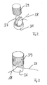
- FIGS. 2 and 3 show such a third intercepting element 36 of the distribution panel 11 of the Fig. 1 in alone view, wherein the third intercepting element 36 has a slotted, rod-shaped attachment portion 37 for integrated into a cable sheath of a fiber optic cable to be inserted Keflarmaschinen 38.
- the keflar fibers 38 may be wrapped around the slotted rod-shaped attachment portion 37 and knotted in this wound position at the attachment portion 37.
- a cap 39 is used, which can be pushed over the attachment section 37.
- the interception elements 40 for the loose tubes are, as well as all other interception elements 34, 35 and 36 and all guide elements 20, 21, 22, 26 and 27 and the trays 19 for the splices, an integral part of running as a plastic injection molded part 11 distribution panel.
Landscapes
- Physics & Mathematics (AREA)
- General Physics & Mathematics (AREA)
- Optics & Photonics (AREA)
- Light Guides In General And Applications Therefor (AREA)
- Polarising Elements (AREA)
- Laser Surgery Devices (AREA)
- Manufacture, Treatment Of Glass Fibers (AREA)
- Mechanical Coupling Of Light Guides (AREA)
Claims (6)
- Dispositif de distribution de fibres optiques, notamment pour les fibres optiques prééquipées de connecteurs à une extrémité comme par exemple les pigtails, avec un espace de distribution (11) comprenant des accouplements pour les connecteurs des fibres optiques prééquipées, des blocages contre la traction (25) pour au moins un câble de fibres optiques à introduire dans l'espace de distribution, des rangements (19) pour des épissures entre les fibres optiques prééquipées et les fibres optiques du ou de chaque câble de fibres optiques, ainsi que des éléments de guidage (20, 21, 22, 26, 27) pour les fibres optiques prééquipées et les fibres optiques introduites par l'intermédiaire du ou de chaque câble de fibres optiques, les accouplements et/ou les blocages contre la traction (25) et/ou les rangements (19) et/ou les éléments de guidage (20, 21, 22, 26, 27) étant partie intégrante de l'espace de distribution (11) réalisé d'une pièce par moulage par injection, caractérisé en ce que les blocages contre la traction (25) et les rangements (19) et les éléments de guidage (20, 21, 22, 26, 27) sont placés dans l'espace de distribution (11) de telle sorte que l'espace de distribution (11) offre au moins trois zones fonctionnelles (29, 30, 31) géométriquement séparées, en l'occurrence une première zone fonctionnelle (29) exclusivement pour l'introduction et le blocage contre la traction du ou de chaque câble de fibres optiques dans l'espace de distribution (11), une deuxième zone fonctionnelle (30) exclusivement pour le guidage des fibres optiques prééquipées vers les accouplements des connecteurs correspondants, et une troisième zone fonctionnelle (31) pour le guidage des fibres optiques prééquipées ainsi que des fibres optiques introduites par l'intermédiaire du ou de chaque câble dans la zone de l'épissure ainsi que pour le rangement de l'épissure, des traversées (32, 33) pour les fibres optiques étant réalisées entre la première zone fonctionnelle (29) et la troisième zone fonctionnelle (31) ainsi qu'entre la deuxième zone fonctionnelle (30) et la troisième zone fonctionnelle (31), et la troisième zone fonctionnelle (31) comportant des rangements séparés de longueurs résiduelles (23, 28) pour les fibres optiques prééquipées et pour les fibres optiques introduites par l'intermédiaire du ou de chaque câble de fibres optiques ainsi que des éléments de guidage séparés (20, 26) pour le guidage de celles-ci en direction des rangements (19) des épissures en respectant le rayon minimum de courbure admissible, de telle sorte que les fibres optiques prééquipées ainsi que les fibres optiques introduites par l'intermédiaire du ou de chaque câble de fibres optiques peuvent être guidées à l'intérieur de l'espace de distribution (11) sans croisement.
- Dispositif de distribution de fibres optiques selon la revendication 1, caractérisé en ce que la première zone fonctionnelle (29) et la troisième zone fonctionnelle (31) sont placées au voisinage d'une face arrière de l'espace de distribution (11) et la deuxième zone fonctionnelle (30) au voisinage d'une face avant de l'espace de distribution (11).
- Dispositif de distribution de fibres optiques selon la revendication 1 ou 2, caractérisé en ce que dans la zone réalisant la traversée (32) entre la première zone fonctionnelle (29) et la troisième zone fonctionnelle (31), sont réalisés des éléments de blocage (40) des faisceaux de fibres des fibres optiques introduites par l'intermédiaire du ou de chaque câble de fibres optiques, les éléments de blocage (40) des faisceaux de fibres étant partie intégrante de l'espace de distribution (11) réalisé d'une pièce par moulage par injection.
- Dispositif de distribution de fibres optiques selon une ou plusieurs des revendications 1 à 3, caractérisé en ce que les blocages contre la traction (25) et les rangements (19) et les éléments de guidage (20, 21, 22, 26, 27) et éventuellement les accouplements sont partie intégrante de l'espace de distribution (11) réalisé d'une pièce par moulage par injection.
- Dispositif de distribution de fibres optiques selon une ou plusieurs des revendications 1 à 4, caractérisé en ce que les blocages contre la traction (25) pour un câble de fibres optiques à introduire dans l'espace de distribution (11) comportent des premiers éléments de blocage (34) pour une gaine du câble, des deuxièmes éléments de blocage (35) pour un élément central du ou de chaque câble de fibres optiques à introduire, et des troisièmes éléments de blocage (36) pour des éléments de traction (38) intégrés dans la gaine d'un câble de fibres optiques à introduire, notamment des fibres de traction comme par exemple des fibres de Kevlar.
- Dispositif de distribution de fibres optiques selon la revendication 5, caractérisé en ce que les troisièmes éléments de blocage (36) pour les éléments de traction intégrés dans la gaine du câble de fibres optiques à introduire, peuvent être recouverts par un capuchon (39).
Applications Claiming Priority (2)
| Application Number | Priority Date | Filing Date | Title |
|---|---|---|---|
| DE202005011461U DE202005011461U1 (de) | 2005-07-21 | 2005-07-21 | Lichtwellenleiterverteilereinrichtung |
| PCT/EP2006/006540 WO2007009593A1 (fr) | 2005-07-21 | 2006-07-05 | Dispositif de distribution de fibres optiques |
Publications (2)
| Publication Number | Publication Date |
|---|---|
| EP1904881A1 EP1904881A1 (fr) | 2008-04-02 |
| EP1904881B1 true EP1904881B1 (fr) | 2010-09-08 |
Family
ID=35070980
Family Applications (1)
| Application Number | Title | Priority Date | Filing Date |
|---|---|---|---|
| EP06762411A Not-in-force EP1904881B1 (fr) | 2005-07-21 | 2006-07-05 | Dispositif de distribution de fibres optiques |
Country Status (7)
| Country | Link |
|---|---|
| EP (1) | EP1904881B1 (fr) |
| AT (1) | ATE480790T1 (fr) |
| CA (1) | CA2614937A1 (fr) |
| DE (2) | DE202005011461U1 (fr) |
| ES (1) | ES2352214T3 (fr) |
| MX (1) | MX2008000958A (fr) |
| WO (1) | WO2007009593A1 (fr) |
Families Citing this family (5)
| Publication number | Priority date | Publication date | Assignee | Title |
|---|---|---|---|---|
| US7970249B2 (en) * | 2008-02-15 | 2011-06-28 | Adc Telecommunications, Inc. | Fiber optic splice enclosure |
| DE202009014308U1 (de) * | 2009-10-22 | 2009-12-17 | CCS Technology, Inc., Wilmington | Pigtail-Handhabungseinrichtung und Lichtwellenleiterverteilereinrichtung |
| WO2013091716A1 (fr) | 2011-12-22 | 2013-06-27 | Prysmian S.P.A. | Ensemble de retenue d'éléments de renfort souples d'un câble optique |
| PL2989494T3 (pl) * | 2013-04-24 | 2020-12-28 | Prysmian S.P.A. | Urządzenie, zespół i sposób mocowania i przytrzymywania kabla optycznego |
| DE202015106837U1 (de) * | 2015-12-16 | 2016-01-11 | ZweiCom GmbH | Glasfaseranschlussdose |
Family Cites Families (7)
| Publication number | Priority date | Publication date | Assignee | Title |
|---|---|---|---|---|
| FR2646928B1 (fr) * | 1989-05-11 | 1993-12-24 | Etat Francais Cnet | Module et boitier de raccordement de cables a fibres optiques |
| AU6278290A (en) * | 1989-09-29 | 1991-04-28 | Northern Telecom Limited | Connector holders and distribution frame and connector holder assemblies for optical cable |
| FR2682775B1 (fr) * | 1991-10-17 | 1995-10-20 | Pouyet Henri | Dispositif d'amarrage de cables a fibres optiques. |
| DE4231181C1 (en) * | 1992-09-17 | 1993-08-26 | Siemens Ag, 8000 Muenchen, De | Cable restraint for fibre=optic cable distribution box - comprises U=shaped fixing shell fastened to rail which mounts screw for fixing cable central strain element |
| FR2723487B1 (fr) * | 1994-08-02 | 1996-10-25 | Crespel Daniel | Dispositif d'amarrage pour cables de telecommunications |
| US6253016B1 (en) * | 1999-08-31 | 2001-06-26 | Lucent Technologies, Inc. | Wall mounted fiber splice enclosure |
| DE202004017493U1 (de) * | 2004-11-11 | 2004-12-30 | CCS Technology, Inc., Wilmington | Lichtwellenleiterverteilereinrichtung |
-
2005
- 2005-07-21 DE DE202005011461U patent/DE202005011461U1/de not_active Expired - Lifetime
-
2006
- 2006-07-05 EP EP06762411A patent/EP1904881B1/fr not_active Not-in-force
- 2006-07-05 MX MX2008000958A patent/MX2008000958A/es unknown
- 2006-07-05 DE DE502006007855T patent/DE502006007855D1/de active Active
- 2006-07-05 ES ES06762411T patent/ES2352214T3/es active Active
- 2006-07-05 AT AT06762411T patent/ATE480790T1/de active
- 2006-07-05 CA CA002614937A patent/CA2614937A1/fr not_active Abandoned
- 2006-07-05 WO PCT/EP2006/006540 patent/WO2007009593A1/fr not_active Ceased
Also Published As
| Publication number | Publication date |
|---|---|
| CA2614937A1 (fr) | 2007-01-25 |
| ES2352214T3 (es) | 2011-02-16 |
| WO2007009593A1 (fr) | 2007-01-25 |
| MX2008000958A (es) | 2008-03-27 |
| EP1904881A1 (fr) | 2008-04-02 |
| DE502006007855D1 (de) | 2010-10-21 |
| ATE480790T1 (de) | 2010-09-15 |
| DE202005011461U1 (de) | 2005-09-29 |
Similar Documents
| Publication | Publication Date | Title |
|---|---|---|
| DE3886583T2 (de) | Faseroptischer Koppler. | |
| EP1736807B1 (fr) | Dispositif destiné à la fixation de microcâbles dirigés dans des microconduits et de microconduits | |
| EP1891474B1 (fr) | Dispositif de distribution de fibres optiques | |
| DE102005052882B4 (de) | Verfahren und Vorrichtung zum Koppeln von Lichtwellenleitern | |
| EP0844504B1 (fr) | Boíte de connexion pour des cables optiques | |
| EP0043570A1 (fr) | Connecteur pour câbles comportant une multiplicité de guides d'ondes optiques | |
| WO2010072286A1 (fr) | Microcâble de distribution pour la technique de communication optique et procédé de fabrication d'un microcâble de distribution | |
| EP2245492B1 (fr) | Joint pour presse etoupe | |
| EP1904881B1 (fr) | Dispositif de distribution de fibres optiques | |
| DE3833492A1 (de) | Vorrichtung und verfahren zum aufteilen von lichtwellenleitern eines optischen kabels | |
| DE3306502A1 (de) | Spleisstraeger fuer lichtwellenleiterspleisse | |
| EP3304158B1 (fr) | Module d'épissure à stockage intégré des longueurs excédentaires et bloc comprenant tels modules | |
| EP2198335B1 (fr) | Dispositif de retenue de câbles de guides d'ondes optiques | |
| EP2176697B1 (fr) | Manchon pour câbles à fibres optiques | |
| EP1921472B1 (fr) | Dispositif de distribution de fibres optiques | |
| DE4439853A1 (de) | Verbindungs-, Abzweig- oder Aufteilungsmuffe für Lichtwellenleiter-Kabel | |
| DE202009014308U1 (de) | Pigtail-Handhabungseinrichtung und Lichtwellenleiterverteilereinrichtung | |
| EP2328004B1 (fr) | Système constitué d'un connecteur optique et de plusieurs fibres conductrices d'ondes lumineuses reliées à celui-ci | |
| EP3916453B1 (fr) | Dispositif d'interception de traction de câble pour câbles à fibres optiques | |
| DE202005011459U1 (de) | Verteilereinrichtung | |
| EP1744191B1 (fr) | Dispositif destiné à la récupération de câbles | |
| DE202004017493U1 (de) | Lichtwellenleiterverteilereinrichtung | |
| DE19848631C2 (de) | System zur Ankopplung eines Lichtwellenleiterkabels an Kupplungselemente in einem Gehäuse | |
| EP1736808A2 (fr) | Dispositif destiné à la récupération de microcâbles dirigés dans des microconduits tout comme microconduits |
Legal Events
| Date | Code | Title | Description |
|---|---|---|---|
| PUAI | Public reference made under article 153(3) epc to a published international application that has entered the european phase |
Free format text: ORIGINAL CODE: 0009012 |
|
| 17P | Request for examination filed |
Effective date: 20080105 |
|
| AK | Designated contracting states |
Kind code of ref document: A1 Designated state(s): AT BE BG CH CY CZ DE DK EE ES FI FR GB GR HU IE IS IT LI LT LU LV MC NL PL PT RO SE SI SK TR |
|
| DAX | Request for extension of the european patent (deleted) | ||
| 17Q | First examination report despatched |
Effective date: 20090123 |
|
| GRAP | Despatch of communication of intention to grant a patent |
Free format text: ORIGINAL CODE: EPIDOSNIGR1 |
|
| GRAS | Grant fee paid |
Free format text: ORIGINAL CODE: EPIDOSNIGR3 |
|
| GRAA | (expected) grant |
Free format text: ORIGINAL CODE: 0009210 |
|
| AK | Designated contracting states |
Kind code of ref document: B1 Designated state(s): AT BE BG CH CY CZ DE DK EE ES FI FR GB GR HU IE IS IT LI LT LU LV MC NL PL PT RO SE SI SK TR |
|
| REG | Reference to a national code |
Ref country code: GB Ref legal event code: FG4D Free format text: NOT ENGLISH |
|
| REG | Reference to a national code |
Ref country code: CH Ref legal event code: EP |
|
| REG | Reference to a national code |
Ref country code: IE Ref legal event code: FG4D Free format text: LANGUAGE OF EP DOCUMENT: GERMAN |
|
| REF | Corresponds to: |
Ref document number: 502006007855 Country of ref document: DE Date of ref document: 20101021 Kind code of ref document: P |
|
| REG | Reference to a national code |
Ref country code: NL Ref legal event code: VDEP Effective date: 20100908 |
|
| PG25 | Lapsed in a contracting state [announced via postgrant information from national office to epo] |
Ref country code: LT Free format text: LAPSE BECAUSE OF FAILURE TO SUBMIT A TRANSLATION OF THE DESCRIPTION OR TO PAY THE FEE WITHIN THE PRESCRIBED TIME-LIMIT Effective date: 20100908 Ref country code: FI Free format text: LAPSE BECAUSE OF FAILURE TO SUBMIT A TRANSLATION OF THE DESCRIPTION OR TO PAY THE FEE WITHIN THE PRESCRIBED TIME-LIMIT Effective date: 20100908 |
|
| REG | Reference to a national code |
Ref country code: ES Ref legal event code: FG2A Effective date: 20110204 |
|
| LTIE | Lt: invalidation of european patent or patent extension |
Effective date: 20100908 |
|
| PG25 | Lapsed in a contracting state [announced via postgrant information from national office to epo] |
Ref country code: SI Free format text: LAPSE BECAUSE OF FAILURE TO SUBMIT A TRANSLATION OF THE DESCRIPTION OR TO PAY THE FEE WITHIN THE PRESCRIBED TIME-LIMIT Effective date: 20100908 Ref country code: CY Free format text: LAPSE BECAUSE OF FAILURE TO SUBMIT A TRANSLATION OF THE DESCRIPTION OR TO PAY THE FEE WITHIN THE PRESCRIBED TIME-LIMIT Effective date: 20100908 Ref country code: PL Free format text: LAPSE BECAUSE OF FAILURE TO SUBMIT A TRANSLATION OF THE DESCRIPTION OR TO PAY THE FEE WITHIN THE PRESCRIBED TIME-LIMIT Effective date: 20100908 |
|
| REG | Reference to a national code |
Ref country code: IE Ref legal event code: FD4D |
|
| PG25 | Lapsed in a contracting state [announced via postgrant information from national office to epo] |
Ref country code: LV Free format text: LAPSE BECAUSE OF FAILURE TO SUBMIT A TRANSLATION OF THE DESCRIPTION OR TO PAY THE FEE WITHIN THE PRESCRIBED TIME-LIMIT Effective date: 20100908 Ref country code: NL Free format text: LAPSE BECAUSE OF FAILURE TO SUBMIT A TRANSLATION OF THE DESCRIPTION OR TO PAY THE FEE WITHIN THE PRESCRIBED TIME-LIMIT Effective date: 20100908 Ref country code: GR Free format text: LAPSE BECAUSE OF FAILURE TO SUBMIT A TRANSLATION OF THE DESCRIPTION OR TO PAY THE FEE WITHIN THE PRESCRIBED TIME-LIMIT Effective date: 20101209 Ref country code: SE Free format text: LAPSE BECAUSE OF FAILURE TO SUBMIT A TRANSLATION OF THE DESCRIPTION OR TO PAY THE FEE WITHIN THE PRESCRIBED TIME-LIMIT Effective date: 20100908 |
|
| PG25 | Lapsed in a contracting state [announced via postgrant information from national office to epo] |
Ref country code: IE Free format text: LAPSE BECAUSE OF FAILURE TO SUBMIT A TRANSLATION OF THE DESCRIPTION OR TO PAY THE FEE WITHIN THE PRESCRIBED TIME-LIMIT Effective date: 20100908 |
|
| PG25 | Lapsed in a contracting state [announced via postgrant information from national office to epo] |
Ref country code: PT Free format text: LAPSE BECAUSE OF FAILURE TO SUBMIT A TRANSLATION OF THE DESCRIPTION OR TO PAY THE FEE WITHIN THE PRESCRIBED TIME-LIMIT Effective date: 20110110 Ref country code: IS Free format text: LAPSE BECAUSE OF FAILURE TO SUBMIT A TRANSLATION OF THE DESCRIPTION OR TO PAY THE FEE WITHIN THE PRESCRIBED TIME-LIMIT Effective date: 20110108 Ref country code: RO Free format text: LAPSE BECAUSE OF FAILURE TO SUBMIT A TRANSLATION OF THE DESCRIPTION OR TO PAY THE FEE WITHIN THE PRESCRIBED TIME-LIMIT Effective date: 20100908 Ref country code: CZ Free format text: LAPSE BECAUSE OF FAILURE TO SUBMIT A TRANSLATION OF THE DESCRIPTION OR TO PAY THE FEE WITHIN THE PRESCRIBED TIME-LIMIT Effective date: 20100908 Ref country code: EE Free format text: LAPSE BECAUSE OF FAILURE TO SUBMIT A TRANSLATION OF THE DESCRIPTION OR TO PAY THE FEE WITHIN THE PRESCRIBED TIME-LIMIT Effective date: 20100908 Ref country code: SK Free format text: LAPSE BECAUSE OF FAILURE TO SUBMIT A TRANSLATION OF THE DESCRIPTION OR TO PAY THE FEE WITHIN THE PRESCRIBED TIME-LIMIT Effective date: 20100908 |
|
| PLBE | No opposition filed within time limit |
Free format text: ORIGINAL CODE: 0009261 |
|
| STAA | Information on the status of an ep patent application or granted ep patent |
Free format text: STATUS: NO OPPOSITION FILED WITHIN TIME LIMIT |
|
| 26N | No opposition filed |
Effective date: 20110609 |
|
| PG25 | Lapsed in a contracting state [announced via postgrant information from national office to epo] |
Ref country code: DK Free format text: LAPSE BECAUSE OF FAILURE TO SUBMIT A TRANSLATION OF THE DESCRIPTION OR TO PAY THE FEE WITHIN THE PRESCRIBED TIME-LIMIT Effective date: 20100908 |
|
| REG | Reference to a national code |
Ref country code: DE Ref legal event code: R097 Ref document number: 502006007855 Country of ref document: DE Effective date: 20110609 |
|
| BERE | Be: lapsed |
Owner name: CCS TECHNOLOGY, INC. Effective date: 20110731 |
|
| PG25 | Lapsed in a contracting state [announced via postgrant information from national office to epo] |
Ref country code: MC Free format text: LAPSE BECAUSE OF NON-PAYMENT OF DUE FEES Effective date: 20110731 |
|
| REG | Reference to a national code |
Ref country code: CH Ref legal event code: PL |
|
| PG25 | Lapsed in a contracting state [announced via postgrant information from national office to epo] |
Ref country code: CH Free format text: LAPSE BECAUSE OF NON-PAYMENT OF DUE FEES Effective date: 20110731 Ref country code: LI Free format text: LAPSE BECAUSE OF NON-PAYMENT OF DUE FEES Effective date: 20110731 Ref country code: BE Free format text: LAPSE BECAUSE OF NON-PAYMENT OF DUE FEES Effective date: 20110731 |
|
| PG25 | Lapsed in a contracting state [announced via postgrant information from national office to epo] |
Ref country code: IT Free format text: LAPSE BECAUSE OF NON-PAYMENT OF DUE FEES Effective date: 20110705 |
|
| REG | Reference to a national code |
Ref country code: AT Ref legal event code: MM01 Ref document number: 480790 Country of ref document: AT Kind code of ref document: T Effective date: 20110705 |
|
| PG25 | Lapsed in a contracting state [announced via postgrant information from national office to epo] |
Ref country code: AT Free format text: LAPSE BECAUSE OF NON-PAYMENT OF DUE FEES Effective date: 20110705 |
|
| PG25 | Lapsed in a contracting state [announced via postgrant information from national office to epo] |
Ref country code: LU Free format text: LAPSE BECAUSE OF NON-PAYMENT OF DUE FEES Effective date: 20110705 |
|
| PG25 | Lapsed in a contracting state [announced via postgrant information from national office to epo] |
Ref country code: TR Free format text: LAPSE BECAUSE OF FAILURE TO SUBMIT A TRANSLATION OF THE DESCRIPTION OR TO PAY THE FEE WITHIN THE PRESCRIBED TIME-LIMIT Effective date: 20100908 Ref country code: BG Free format text: LAPSE BECAUSE OF FAILURE TO SUBMIT A TRANSLATION OF THE DESCRIPTION OR TO PAY THE FEE WITHIN THE PRESCRIBED TIME-LIMIT Effective date: 20101208 |
|
| PG25 | Lapsed in a contracting state [announced via postgrant information from national office to epo] |
Ref country code: HU Free format text: LAPSE BECAUSE OF FAILURE TO SUBMIT A TRANSLATION OF THE DESCRIPTION OR TO PAY THE FEE WITHIN THE PRESCRIBED TIME-LIMIT Effective date: 20100908 |
|
| PGFP | Annual fee paid to national office [announced via postgrant information from national office to epo] |
Ref country code: DE Payment date: 20140729 Year of fee payment: 9 |
|
| PGFP | Annual fee paid to national office [announced via postgrant information from national office to epo] |
Ref country code: FR Payment date: 20140717 Year of fee payment: 9 Ref country code: ES Payment date: 20140728 Year of fee payment: 9 |
|
| PGFP | Annual fee paid to national office [announced via postgrant information from national office to epo] |
Ref country code: GB Payment date: 20150727 Year of fee payment: 10 |
|
| REG | Reference to a national code |
Ref country code: DE Ref legal event code: R119 Ref document number: 502006007855 Country of ref document: DE |
|
| PG25 | Lapsed in a contracting state [announced via postgrant information from national office to epo] |
Ref country code: DE Free format text: LAPSE BECAUSE OF NON-PAYMENT OF DUE FEES Effective date: 20160202 |
|
| REG | Reference to a national code |
Ref country code: FR Ref legal event code: ST Effective date: 20160331 |
|
| PG25 | Lapsed in a contracting state [announced via postgrant information from national office to epo] |
Ref country code: FR Free format text: LAPSE BECAUSE OF NON-PAYMENT OF DUE FEES Effective date: 20150731 |
|
| REG | Reference to a national code |
Ref country code: ES Ref legal event code: FD2A Effective date: 20160826 |
|
| PG25 | Lapsed in a contracting state [announced via postgrant information from national office to epo] |
Ref country code: ES Free format text: LAPSE BECAUSE OF NON-PAYMENT OF DUE FEES Effective date: 20150706 |
|
| GBPC | Gb: european patent ceased through non-payment of renewal fee |
Effective date: 20160705 |
|
| PG25 | Lapsed in a contracting state [announced via postgrant information from national office to epo] |
Ref country code: GB Free format text: LAPSE BECAUSE OF NON-PAYMENT OF DUE FEES Effective date: 20160705 |