EP1904892B1 - Architekturen zur dreidimensionalen stereoskopischen projektion - Google Patents
Architekturen zur dreidimensionalen stereoskopischen projektion Download PDFInfo
- Publication number
- EP1904892B1 EP1904892B1 EP06760744A EP06760744A EP1904892B1 EP 1904892 B1 EP1904892 B1 EP 1904892B1 EP 06760744 A EP06760744 A EP 06760744A EP 06760744 A EP06760744 A EP 06760744A EP 1904892 B1 EP1904892 B1 EP 1904892B1
- Authority
- EP
- European Patent Office
- Prior art keywords
- light
- output
- image
- port
- modulation
- Prior art date
- Legal status (The legal status is an assumption and is not a legal conclusion. Google has not performed a legal analysis and makes no representation as to the accuracy of the status listed.)
- Not-in-force
Links
Images
Classifications
-
- G—PHYSICS
- G03—PHOTOGRAPHY; CINEMATOGRAPHY; ANALOGOUS TECHNIQUES USING WAVES OTHER THAN OPTICAL WAVES; ELECTROGRAPHY; HOLOGRAPHY
- G03B—APPARATUS OR ARRANGEMENTS FOR TAKING PHOTOGRAPHS OR FOR PROJECTING OR VIEWING THEM; APPARATUS OR ARRANGEMENTS EMPLOYING ANALOGOUS TECHNIQUES USING WAVES OTHER THAN OPTICAL WAVES; ACCESSORIES THEREFOR
- G03B35/00—Stereoscopic photography
- G03B35/18—Stereoscopic photography by simultaneous viewing
- G03B35/26—Stereoscopic photography by simultaneous viewing using polarised or coloured light separating different viewpoint images
-
- G—PHYSICS
- G02—OPTICS
- G02B—OPTICAL ELEMENTS, SYSTEMS OR APPARATUS
- G02B30/00—Optical systems or apparatus for producing three-dimensional [3D] effects, e.g. stereoscopic images
- G02B30/20—Optical systems or apparatus for producing three-dimensional [3D] effects, e.g. stereoscopic images by providing first and second parallax images to an observer's left and right eyes
- G02B30/22—Optical systems or apparatus for producing three-dimensional [3D] effects, e.g. stereoscopic images by providing first and second parallax images to an observer's left and right eyes of the stereoscopic type
- G02B30/25—Optical systems or apparatus for producing three-dimensional [3D] effects, e.g. stereoscopic images by providing first and second parallax images to an observer's left and right eyes of the stereoscopic type using polarisation techniques
-
- H—ELECTRICITY
- H04—ELECTRIC COMMUNICATION TECHNIQUE
- H04N—PICTORIAL COMMUNICATION, e.g. TELEVISION
- H04N13/00—Stereoscopic video systems; Multi-view video systems; Details thereof
- H04N13/30—Image reproducers
- H04N13/363—Image reproducers using image projection screens
Definitions
- This invention relates to optical architectures that project polarization-encoded three-dimensional stereoscopic images.
- Three-dimensional displays can be of several forms. Those such as holographic displays form an exact optical representation of three-dimensional objects through phase and amplitude modulation of light. Others recreate three-dimensional information using volume displays such as a series of synchronized modulating two-dimensional screens. Although, these approaches more closely reproduce true three-dimensional images, they are very demanding of hardware and at present can only form very crude images. A more practical approach is to form stereoscopic images in which one image is seen only by the right eye and a second image by the left. The difference between the images yields depth information, thereby providing a strong three-dimensional sensation whereby objects appear to be only a few meters away from a viewer in a cinema environment.
- stereoscopic images are viewed through eyewear that discriminates between the eyes.
- Eyewear can discriminate through colour wherein one eye can be made to see one portion of the visible spectrum while the other eye sees a complementary portion of the spectrum.
- Encoding the stereoscopic images in the same colour bands can yield a three-dimensional sensation although the obvious difference in what the eyes see causes fatigue. Consequently, other systems and methods of providing three-dimensional images would be useful.
- US 2005/0046759 discloses a stereoscopic image projection system comprising four beam splitters, and two spatial light modulators S1 and S2.
- Light from a light source is directed through a colour wheel 13 into the first polarising beam splitter 14.
- S polarised light is directed towards a second polarising beam splitter 18, which in turn directs the light towards the spatial light modulator S1.
- P polarised light is directed towards the imager S2.
- Light reflected from the imagers S1 and S2 passes back into the respective polarising beam splitters 18 and 16, where it is further directed towards, and recombined in, the fourth polarising beam splitter 20.
- W02004/046787 discloses a image projection system using a dichroic beam splitter, and three polarising beam splitters, and three spatial light modulators, each handling a separate colour band in a colour image.
- US 2003/0214635 discloses a system which as shown in Figure 1 thereof has dichroic beam splitters and four polarising beam splitters in order to modulate the blue and red components of an image. Furthermore, as shown in Figure 2 thereof it uses another three polarising beam splitters to produce a green image.
- EP 1143744 also uses multiple polarising beam splitters to handle different colour components of a spatially light modulated image.
- EP 0837351 discloses using three LCD spatial light modulators to modulate red, green and blue images and to recombine them to form a colour image.
- a system as defined in independent claim 1, operable to provide stereoscopic images comprising: a light splitting and combining element having an input port, first and second modulation ports, and an output port, the light splitting and combining element being operable to receive unpolarised light through the input port and split the unpolarised light into first and second orthogonal polarisation light components, and where the light splitting and combining element is operable to direct the first and second polarised light components to the first and second modulation ports respectively; a first image projection subsystem comprising a first light modulator and a first retarder element and wherein the first light modulator is disposed proximate to the first modulation port and the first retarder element is disposed between the first light modulator and the first modulation port, the first image projection subsystem is operable to receive the first polarised light component and provide a first stereo image output formed by light having a first output polarisation, and where the polarisations of the first light component and the first output polarisation are
- a method of providing stereoscopic visible images comprising the steps of: providing a light splitting and combining element having an input port, first and second modulation ports, and an output port, wherein the light splitting and combining element comprises a single polarizing beam splitter, directing unpolarised light to the input port of the light splitting and combing element; splitting the unpolarised light into first and second illumination lights having first and second input polarisations; directing the first illumination light through the first modulation port of the light splitting and combining element to a first image projection subsystem, the first image projection subsystem comprising a first light modulator disposed proximate to the first modulation port and a 45°-oriented achromatic quarter-wave plate disposed in between the first light modulator and the first modulation port, wherein the first light modulator comprises a digital micro-mirror device panel; directing the second illumination light through the second modulation port of the light splitting and combining element to a second image projection
- any polarization-based discrimination technique With any polarization-based discrimination technique, complete two-dimensional images are formed with orthogonal polarization states. Although this can be done by spatially patterning direct-view displays with micro-polarisers, or by time-sequentially altering the output polarization state of a display in synchronization with time-sequential images, one solution is to continuously display two full-colour, high-resolution, orthogonal polarised images. Since this would demand, in general, two displays, it well-suited to projection systems where the image modulator is compact and potentially low cost.
- Embodiments of this invention employ micro-display projection systems that produce stereo-images with orthogonal polarization states using a common illumination source and a common projection lens.
- stereo-images refers to a pair of images that form slightly different views, usually by a rotational off-set, of a scene on each retina, thereby providing a three-dimensional appearance to the scene. Pairs of images that provide substantially the same view are perceived to lack three- dimensionality and are referred to as non-stereo-images.
- the common illumination source and common projection lens serves to provide, respectively, colour balance and image registration. Using separate sources for each image can lead to colour balance mismatch, especially as currently used high-brightness sources age.
- a single projection lens provides for registration of the images before the projection lens, and registration in this approach is therefore maintained for different imaging settings such as the distance and angle to screen and tolerance of zoom.
- two digital micro-mirror device modulators such as those used by Texas Instruments in its Digital Light Processing(TM) architectures, are used to form the stereoscopic images, but other embodiments may use liquid crystal (LC) or liquid crystal.
- LC liquid crystal
- the exemplary embodiment provides for colour sharing, using colour-sequential sub-systems operable to provide the colour sharing between first and second channels.
- An example would be in a digital micro-mirror device system where RGB (Red, Green, Blue) colour frames sequentially illuminate a panel to form a colour image.
- RGB Red, Green, Blue
- the complementary colour can be used to illuminate the second kernel.
- the primary colours are alternated between sub-systems. Since each image is formed from the summation of primary and complementary colours, the maximum three-dimensional colour gamut is distorted with respect to standard video projection systems and correction and some accompanying light loss may be necessary in those instances.
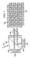
- FIGURE 1 illustrates an exemplary embodiment of a two-panel digital micro-mirror device system.
- Unpolarised, white illumination light 101 enters an off-45° polarizing beam splitter (PBS) 102, which acts to split the unpolarised, white light 101 into its two orthogonal polarization components.
- PBS off-45° polarizing beam splitter
- Each illuminates a digital micro-mirror device panel 103 by first passing through a 45°-oriented achromatic quarter-wave plate (QWP) 104 adjacent each panel 103.
- QWP achromatic quarter-wave plate
- the purpose of the quarter-wave plates is to alter the polarization state of reflected light from each panel. Modulation between "ON” and “OFF” pixels is achieved in the conventional manner by deflecting light into and away from the capture of the projection lens (not shown).
- Contrasts similar to conventional digital micro-mirror device systems can therefore be expected.
- Light that is deflected from "ON" pixels is directed toward the projection lens either by transmission through or reflection off the polarization beam splitter. In this way they have substantially orthogonal polarization states.
- Colour in this system is formed through colour-sequential illumination. As with conventional digital micro-mirror device systems, this may be done with a colour wheel, since no polarization demands are placed on the illumination.
- the illumination system would therefore constitute a conventional source such as an ultra high pressure (UHP) mercury lamp focused with an elliptical reflector into a rectangular cross-section light pipe. Before entering the light pipe, the beam would pass through the colour wheel, which through rotation of colour segments is able to break the beam into primary colour sequential illumination frames. Synchronization between the panel modulation and these colour frames allows for full-colour representation. Imaging onto panels via relay optics occurs after exiting the light pipe. Since no polarization conversion is needed, the exiting aperture can be imaged with minimal light loss onto small panels. Exemplary small panels are approximately 1.27 cm (.5 inches) diagonally. Envisioned embodiments may include LED illuminators allowing temporal control of colour by direct modulation, avoiding using a colour wheel.
- FIGURE 1 also shows diagrammatically the overlapping pixel patterns 106, 107 which allow higher resolution imagery to be realized.
- Such overlapping patterns 106, 107 mimics, in a time stationary manner, the so-called "wobbling" technique known in the art to enhance resolution.
- This method of increasing resolution is in its own right a significant cost advantage since yield rates of smaller chips are significantly higher than those with four times the area making two half resolution chips far less costly than a single chip with full resolution.
- This approach is particularly advantageous in the embodiments disclosed herein, however, because of the synergies of using the subsystems employed to achieve three-dimensional images to provide higher-resolution two- dimensional images without the need for increased hardware.
Landscapes
- Physics & Mathematics (AREA)
- General Physics & Mathematics (AREA)
- Optics & Photonics (AREA)
- Engineering & Computer Science (AREA)
- Multimedia (AREA)
- Signal Processing (AREA)
- Testing, Inspecting, Measuring Of Stereoscopic Televisions And Televisions (AREA)
- Stereoscopic And Panoramic Photography (AREA)
- Radiation-Therapy Devices (AREA)
- Led Device Packages (AREA)
- Finger-Pressure Massage (AREA)
- Optical Elements Other Than Lenses (AREA)
- Liquid Crystal (AREA)
- Length Measuring Devices By Optical Means (AREA)
Claims (10)
- Ein bedienbares System zur Bereitstellung von Raumbildern, welches Folgendes umfasst:ein lichttrennendes und -vereinigendes Element (102) mit einem Eingangskanal, ersten und zweiten Modulationskanal und einem Ausgabekanal, wobei das lichttrennende und -vereinigende Element bedient werden kann, um unpolarisiertes Licht (101) durch den Eingangskanal zu empfangen und das unpolarisierte Licht in erste und zweite orthogonale Polarisationslichtkomponenten aufzuteilen, und wobei das lichttrennende und -vereinigende Element bedient werden kann, um die ersten und zweiten polarisierten Lichtkomponenten jeweils zu den ersten und zweiten Modulationskanälen zu leiten;Ein erstes Bildprojektions-Teilsystem, bestehend aus einem ersten Lichtmodulator (103) und einem ersten Verzögererelement (104), und wobei der erste Lichtmodulator unmittelbar bei dem ersten Modulationskanal und das erste Verzögererelement zwischen dem ersten Lichtmodulator und dem ersten Modulationskanal angeordnet ist, wobei das erste Bildprojektions-Teilsystem bedienbar ist, um die erste polarisierte Lichtkomponente zu empfangen und um eine erste Stereobildausgabe durch Licht bereitzustellen, die eine erste Ausgabepolarisation hat, und wobei die Polarisationen der ersten Lichtkomponente und der ersten Ausgabepolarisation im Wesentlichen orthogonal sind;ein zweites Bildprojektions-Teilsystem, bestehend aus einem zweiten Lichtmodulator (103) und einem zweiten Verzögererelement (104), und wobei der zweite Lichtmodulator unmittelbar bei dem zweiten Modulationskanal und das zweite Verzögererelement zwischen dem zweiten Lichtmodulator und dem zweiten Modulationskanal angeordnet ist, wobei das zweite Bildprojektions-Teilsystem bedienbar ist, um die zweite polarisierte Lichtkomponente zu empfangen und eine zweite Stereobildausgabe bereitzustellen, welche durch Licht gebildet wird, die über eine zweite Ausgabepolarisation verfügt und wobei die zweite Polarisationslichtkomponente und die zweite Ausgabepolarisation im Wesentlichen orthogonal sind; und wobei die ersten und zweiten Ausgabepolarisationen im Wesentlichen orthogonal sind; dadurch gekennzeichnet, dass:der erste Lichtmodulator eine digitale Mikrospiegel-Gerätekonsole umfasst, und das erste Verzögererelement eine in 45-Grad-Richtung orientierte achromatische Viertelwellenplatte umfasst;ein zweiter Lichtmodulator eine digitale Mikrospiegel-Gerätekonsole umfasst, und dass das zweite Verzögererelement eine in 45-Grad-Richtung orientierte achromatische Viertelwellenplatte umfasst; unddas lichttrennende und -vereinigende Element die ersten und zweiten Stereobildausgäben jeweils in den ersten und zweiten Modulationskanälen empfängt und eingerichtet ist, um diese zu vereinigen und das kombinierte Bild durch den Ausgabekanal in Richtung einer Linse leitet, in de das lichttrennende und -vereinigende Element einen einzelnen polarisierenden Strahlenleiter umfasst.
- Das System nach Anspruch 1, dadurch gekennzeichnet, dass es weiterhin eine Viertelwellenplatte (105) unmittelbar bei dem Ausgabekanal des lichttrennenden und - vereinigenden Elements umfasst.
- Das System nach Anspruch 1 oder 2, dadurch gekennzeichnet, dass das erste Bildprojektions-Teilsystem fortlaufend die erste Bildausgabe während des Betriebs anzeigt.
- Das System nach Anspruch 3, dadurch gekennzeichnet, dass das zweite Bildprojektions-Teilsystem fortlaufend die zweite Bildausgabe während des Betriebs anzeigt.
- Das System nach einem der vorhergehenden Ansprüche, dadurch gekennzeichnet, dass es weiterhin über eine Lichtquelle unmittelbar bei dem Eingangskanal sowie auch über ein Lichtrad verfügt, welches zwischen der Lichtquelle und dem Eingangskanal angeordnet ist.
- Ein System, wie in einem der vorhergehenden Ansprüche beansprucht, dadurch gekennzeichnet, dass die ersten und zweiten Verzögererelemente Viertelwellenplatten sind und dass die ersten und zweiten Polarisationslichtkomponenten linear polarisiert sind.
- Eine Methode zur Bereitstellung von sichtbaren Raumbildern, welche folgende Ablaufschritte umfasst:Bereitstellung eines lichttrennenden und -vereinigenden Elements (102) mit einem Eingangskanal, ersten und zweiten Modulationskanälen und einem Ausgangskanal, wobei das lichttrennende und -vereinigende Element einen einzelnen polarisierenden Strahlenteiler umfasst,und unpolarisiertes Licht zu dem Eingangskanl des lichttrennenden und - vereinigenden Elements geleitet wird;unpolarisiertes Licht in erste und zweite Beleuchtungslichter geteilt wird, welche über erste und zweite Eingangspolarisationen verfügen;Leitung eines ersten Beleuchtungslichts durch einen ersten Modulationskanal des lichttrennenden und -vereinigenden Elements zu einem ersten Bildprojektions-Teilsystem, wobei in dem ersten Bildprojektions-Teilsystem ein erster Lichtmodulator vorgesehen ist, der unmittelbar bei dem ersten Modulationskanal angeordnet ist und eine in 45-Grad-Richtung orientierte achromatische Viertelwellenplatte zwischen dem ersten Lichtmodulator und dem ersten Modulationskanal angeordnet ist, in dem der erste Lichtmodulator eine digitale Mikrospiegel-Gerätekonsole umfasst;Leitung eines zweiten Beleuchtungslichts durch einen zweiten Modulationskanal des lichttrennenden und -vereinigenden Elements zu einem zweiten Bildprojektions-Teilsystem, wobei in dem zweiten Bildprojektions-Teilsystem ein zweiter Lichtmodulator vorgesehen ist, welcher unmittelbar neben dem zweiten Modulationskanal angeordnet ist, und eine in 45-Grad-Richtung orientierte achromatische Viertelwellenplatte zwischen dem zweiten Lichtmodulator und dem zweiten Modulationskanal angeordnet ist, in dem der zweite Lichtmodulator über eine digitale Mikrospiegel-Gerätekonsole verfügt;Bereitstellung einer ersten Stereobildausgabe im ersten Bildprojektions-Teilsystem, welche von Licht gebildet wurde, das eine erste Ausgabepolarisation hat, wobei die ersten Eingabe- und Ausgabepolarisationen im Wesentlichen orthogonal sind;Bereitstellung einer zweiten Stereobildausgabe im zweiten Bildprojektions-Teilsystem, welche von Licht gebildet wurde, das eine zweite Ausgabepolarisation hat, wobei die zweiten Eingabe- und Ausgabepolarisationen im Wesentlichen orthogonal sind;Leitung der ersten und zweiten Stereobildausgaben zu jeweils den ersten und zweiten Modulationskanälen des lichttrennenden und -vereinigenden Elements; undeine direkte oder indirekte Projektierung der ersten und zweiten StereobildAusgaben auf eine Anzeige durch den Ausgabekanal des lichttrennenden und - vereinigenden Elements und einer gemeinsamen Linse;wobei die ersten und zweiten Ausgabepolarisationen im Wesentlichen orthogonal sind.
- Eine Vorrichtung wie in Anspruch 7 beansprucht, welche weiterhin folgende Ablaufschritte umfasst:Leitung der ersten und zweiten Stereobildausgaben von dem Ausgabekanal des lichttrennenden und;- vereinigenden Elements durch eine Viertelwellenplatte.
- Eine Vorrichtung, wie in Anspruch 7 oder 8 beansprucht, welche weiterhin den Ablaufschritt einer fortlaufenden Bereitstellung und Projektierung der ersten Bildausgabe umfasst.
- Eine Vorrichtung, wie in Anspruch 9 beansprucht, welche weiterhin den Ablaufschritt einer fortlaufenden Bereitstellung und Projektierung der zweiten Bildausgabe umfasst.
Applications Claiming Priority (2)
| Application Number | Priority Date | Filing Date | Title |
|---|---|---|---|
| US68927705P | 2005-06-10 | 2005-06-10 | |
| PCT/US2006/022898 WO2006135867A2 (en) | 2005-06-10 | 2006-06-12 | Three dimensional stereoscopic projection architectures |
Publications (3)
| Publication Number | Publication Date |
|---|---|
| EP1904892A2 EP1904892A2 (de) | 2008-04-02 |
| EP1904892A4 EP1904892A4 (de) | 2009-07-15 |
| EP1904892B1 true EP1904892B1 (de) | 2010-12-22 |
Family
ID=37532879
Family Applications (1)
| Application Number | Title | Priority Date | Filing Date |
|---|---|---|---|
| EP06760744A Not-in-force EP1904892B1 (de) | 2005-06-10 | 2006-06-12 | Architekturen zur dreidimensionalen stereoskopischen projektion |
Country Status (6)
| Country | Link |
|---|---|
| US (1) | US20060290889A1 (de) |
| EP (1) | EP1904892B1 (de) |
| JP (1) | JP2008546040A (de) |
| AT (1) | ATE492833T1 (de) |
| DE (1) | DE602006019097D1 (de) |
| WO (1) | WO2006135867A2 (de) |
Cited By (1)
| Publication number | Priority date | Publication date | Assignee | Title |
|---|---|---|---|---|
| TWI483000B (zh) * | 2012-02-22 | 2015-05-01 | 台達電子工業股份有限公司 | 極化轉換元件組及包含該極化轉換元件組之投影裝置 |
Families Citing this family (28)
| Publication number | Priority date | Publication date | Assignee | Title |
|---|---|---|---|---|
| USD576977S1 (en) | 2000-07-07 | 2008-09-16 | Fergason Patent Properties Llc | Display system |
| US7401923B2 (en) * | 2004-03-09 | 2008-07-22 | Fergason Patent Properties, Llc | Monitor for showing high-resolution and three-dimensional images and method |
| JP4155275B2 (ja) * | 2005-03-25 | 2008-09-24 | セイコーエプソン株式会社 | 画像表示装置 |
| US7690794B2 (en) * | 2006-07-02 | 2010-04-06 | Simon Andrew Boothroyd | Image-combining device and projection display apparatus having image-combining devices incorporated therein |
| FR2904702A1 (fr) * | 2006-12-13 | 2008-02-08 | Thomson Licensing Sas | Dispositif sequentiel de projection a deux imageurs modulant des couleurs complementaires |
| US8259239B2 (en) * | 2007-01-18 | 2012-09-04 | The Arizona Board Of Regents On Behalf Of The University Of Arizona | Polarized head-mounted projection display |
| CN101373275A (zh) * | 2007-08-21 | 2009-02-25 | 鸿富锦精密工业(深圳)有限公司 | 立体投影光学系统 |
| US20100253769A1 (en) * | 2008-09-04 | 2010-10-07 | Laser Light Engines | Optical System and Assembly Method |
| DE102008044334A1 (de) * | 2008-12-04 | 2010-06-10 | Robert Bosch Gmbh | Projektionseinrichtung und Verfahren zur Projektion |
| JP2010217818A (ja) * | 2009-03-19 | 2010-09-30 | Panasonic Corp | 投写型表示装置 |
| JP5263031B2 (ja) * | 2009-06-26 | 2013-08-14 | パナソニック株式会社 | 投写型表示装置 |
| EP2282231A3 (de) * | 2009-08-07 | 2011-05-04 | JDS Uniphase Corporation | Mehrteiliger optischer Verzögerer zur Erzeugung von 3D-Bildern |
| US10678061B2 (en) | 2009-09-03 | 2020-06-09 | Laser Light Engines, Inc. | Low etendue illumination |
| US20110141249A1 (en) * | 2009-12-14 | 2011-06-16 | Huang-Tzung Jan | Stereo-image display apparatus |
| CN101806995A (zh) * | 2010-03-25 | 2010-08-18 | 河北工业大学 | 双液晶光阀单投影机立体投影装置 |
| CN101790062B (zh) * | 2010-03-25 | 2013-05-08 | 深圳市时代华影科技开发有限公司 | 单液晶光阀单投影机立体投影装置 |
| KR101074632B1 (ko) | 2010-07-23 | 2011-10-18 | 옵티시스 주식회사 | 삼차원 디스플레이 장치 |
| JP5675330B2 (ja) * | 2010-12-27 | 2015-02-25 | キヤノン株式会社 | 画像表示装置 |
| US20130135588A1 (en) * | 2011-11-29 | 2013-05-30 | Milan Momcilo Popovich | 3D display apparatus |
| US9004700B2 (en) | 2012-01-25 | 2015-04-14 | International Business Machines Corporation | Three dimensional image projector stabilization circuit |
| US8960913B2 (en) * | 2012-01-25 | 2015-02-24 | International Busniess Machines Corporation | Three dimensional image projector with two color imaging |
| US8985785B2 (en) | 2012-01-25 | 2015-03-24 | International Business Machines Corporation | Three dimensional laser image projector |
| US20130188149A1 (en) | 2012-01-25 | 2013-07-25 | International Business Machines Corporation | Three dimensional image projector |
| US9104048B2 (en) | 2012-01-25 | 2015-08-11 | International Business Machines Corporation | Three dimensional image projector with single modulator |
| US8992024B2 (en) | 2012-01-25 | 2015-03-31 | International Business Machines Corporation | Three dimensional image projector with circular light polarization |
| US9325977B2 (en) | 2012-01-25 | 2016-04-26 | International Business Machines Corporation | Three dimensional LCD monitor display |
| JP6319290B2 (ja) * | 2013-02-27 | 2018-05-09 | ソニー株式会社 | 画像投写装置 |
| US10230928B2 (en) * | 2014-10-27 | 2019-03-12 | Texas Instruments Incorporated | Color recapture using polarization recovery in a color-field sequential display system |
Family Cites Families (50)
| Publication number | Priority date | Publication date | Assignee | Title |
|---|---|---|---|---|
| US4134644A (en) * | 1977-01-10 | 1979-01-16 | Marks Alvin M | 3D Color pictures with multichrome filters |
| GB2040134A (en) * | 1978-11-09 | 1980-08-20 | Marconi Co Ltd | Stereoscopic television systems |
| GB8321727D0 (en) * | 1983-08-12 | 1983-09-14 | Brightad Ltd | Producing stereoscopic images |
| US4620770A (en) * | 1983-10-25 | 1986-11-04 | Howard Wexler | Multi-colored anaglyphs |
| US4719507A (en) * | 1985-04-26 | 1988-01-12 | Tektronix, Inc. | Stereoscopic imaging system with passive viewing apparatus |
| US4995718A (en) * | 1989-11-15 | 1991-02-26 | Honeywell Inc. | Full color three-dimensional projection display |
| KR930003307B1 (ko) * | 1989-12-14 | 1993-04-24 | 주식회사 금성사 | 입체용 프로젝터 |
| US5537144A (en) * | 1990-06-11 | 1996-07-16 | Revfo, Inc. | Electro-optical display system for visually displaying polarized spatially multiplexed images of 3-D objects for use in stereoscopically viewing the same with high image quality and resolution |
| US5481321A (en) * | 1991-01-29 | 1996-01-02 | Stereographics Corp. | Stereoscopic motion picture projection system |
| US5260729A (en) * | 1991-09-23 | 1993-11-09 | Hughes Aircraft Company | Non-interfering color viewing system using spectral multiplexing |
| US5187487A (en) * | 1992-03-05 | 1993-02-16 | General Electric Company | Compact wide tunable bandwidth phased array antenna controller |
| JPH05257110A (ja) * | 1992-03-13 | 1993-10-08 | Sharp Corp | 投射型液晶表示装置 |
| US5564810A (en) * | 1992-12-31 | 1996-10-15 | Honeywell Inc. | Full color stereoscopic display with color multiplexing |
| US6111598A (en) * | 1993-11-12 | 2000-08-29 | Peveo, Inc. | System and method for producing and displaying spectrally-multiplexed images of three-dimensional imagery for use in flicker-free stereoscopic viewing thereof |
| US5537476A (en) * | 1994-11-21 | 1996-07-16 | International Business Machines Corporation | Secure viewing of display units by image superposition and wavelength separation |
| CA2146811C (en) * | 1995-04-11 | 2003-07-01 | David Michael Moore Dean | Method and apparatus for presenting stereoscopic images |
| JPH0996780A (ja) * | 1995-10-03 | 1997-04-08 | Nippon Hoso Kyokai <Nhk> | 投射型立体画像表示システム |
| GB2317524A (en) * | 1996-09-19 | 1998-03-25 | Sharp Kk | Three dimensional stereoscopic projection display |
| US6390626B2 (en) * | 1996-10-17 | 2002-05-21 | Duke University | Image projection system engine assembly |
| US6252570B1 (en) * | 1997-02-25 | 2001-06-26 | Gateway, Inc. | Polarized three-demensional video display |
| US5963371A (en) * | 1998-02-04 | 1999-10-05 | Intel Corporation | Method of displaying private data to collocated users |
| DE19924167B4 (de) * | 1999-05-26 | 2006-05-24 | Daimlerchrysler Ag | Vorrichtung zur Wiedergabe von Farbbildern |
| DE60135889D1 (de) * | 2000-03-17 | 2008-11-06 | Hitachi Ltd | Bildanzeigevorrichtung |
| US6608614B1 (en) * | 2000-06-22 | 2003-08-19 | Rockwell Collins, Inc. | Led-based LCD backlight with extended color space |
| US6888529B2 (en) * | 2000-12-12 | 2005-05-03 | Koninklijke Philips Electronics N.V. | Control and drive circuit arrangement for illumination performance enhancement with LED light sources |
| JP3766274B2 (ja) * | 2000-12-21 | 2006-04-12 | 株式会社東芝 | 時分割カラー表示装置および表示方法 |
| US6978345B2 (en) * | 2001-05-15 | 2005-12-20 | Hewlett-Packard Development Company, L.P. | Self-mirroring high performance disk drive |
| US6672722B2 (en) * | 2001-06-19 | 2004-01-06 | Intel Corporation | Projection engine |
| US6980177B2 (en) * | 2001-08-03 | 2005-12-27 | Waterstrike Incorporated | Sequential inverse encoding apparatus and method for providing confidential viewing of a fundamental display image |
| US6680578B2 (en) * | 2001-09-19 | 2004-01-20 | Osram Opto Semiconductors, Gmbh | Organic light emitting diode light source |
| US6829393B2 (en) * | 2001-09-20 | 2004-12-07 | Peter Allan Jansson | Method, program and apparatus for efficiently removing stray-flux effects by selected-ordinate image processing |
| US6956964B2 (en) * | 2001-11-08 | 2005-10-18 | Silicon Intergrated Systems Corp. | Apparatus for producing real-time anaglyphs |
| EP1337117A1 (de) * | 2002-01-28 | 2003-08-20 | Thomson Licensing S.A. | Stereskopisches Projektionssystem |
| US20050046759A1 (en) * | 2002-01-28 | 2005-03-03 | O'donnell Eugene Murphy | Brighter light engine architecture for a liquid crystal display projection system |
| JP4397565B2 (ja) * | 2002-05-08 | 2010-01-13 | 日本ビクター株式会社 | 液晶プロジェクタ装置 |
| US7002546B1 (en) * | 2002-05-15 | 2006-02-21 | Rockwell Collins, Inc. | Luminance and chromaticity control of an LCD backlight |
| US6769772B2 (en) * | 2002-10-11 | 2004-08-03 | Eastman Kodak Company | Six color display apparatus having increased color gamut |
| TW561306B (en) * | 2002-10-17 | 2003-11-11 | Himax Tech Inc | LCD projection system and illumination device thereof |
| US7196687B2 (en) * | 2002-11-05 | 2007-03-27 | 3M Innovative Properties Company | Swept illumination to reduce LCD lag in front and rear projection displays |
| DE60333583D1 (de) * | 2002-11-14 | 2010-09-09 | Reald Inc | Dreitafelfarbverwaltungssysteme und verfahren |
| US6975369B1 (en) * | 2002-12-12 | 2005-12-13 | Gelcore, Llc | Liquid crystal display with color backlighting employing light emitting diodes |
| JP2004205919A (ja) * | 2002-12-26 | 2004-07-22 | Victor Co Of Japan Ltd | 投射型立体表示装置 |
| KR100995640B1 (ko) * | 2003-07-07 | 2010-11-19 | 엘지디스플레이 주식회사 | 액정표시모듈 |
| CN100476505C (zh) * | 2003-07-18 | 2009-04-08 | 晶荧光学科技有限公司 | 一种三维/二维可切换的彩色投影显示装置及其方法 |
| US20070218372A1 (en) * | 2003-07-24 | 2007-09-20 | Explay Ltd. | Method For Production Of Micro-Optics Structures |
| US20050094267A1 (en) * | 2003-10-17 | 2005-05-05 | Huber Mark J. | Birefringent anaglyph |
| WO2005076883A2 (en) * | 2004-02-05 | 2005-08-25 | Oplink Communications, Inc. | Integrated optical multiplexer and demultiplexer |
| US8384773B2 (en) * | 2004-04-01 | 2013-02-26 | Hewlett-Packard Development Company, L.P. | Method and system for displaying an image in three dimensions |
| KR20050105845A (ko) * | 2004-05-03 | 2005-11-08 | 삼성전자주식회사 | 프로젝션 시스템 |
| TWI253047B (en) * | 2004-06-16 | 2006-04-11 | Chi Mei Optoelectronics Corp | Method for controlling operations of a backlight unit of a liquid crystal display |
-
2006
- 2006-06-12 US US11/423,574 patent/US20060290889A1/en not_active Abandoned
- 2006-06-12 JP JP2008516028A patent/JP2008546040A/ja active Pending
- 2006-06-12 EP EP06760744A patent/EP1904892B1/de not_active Not-in-force
- 2006-06-12 DE DE602006019097T patent/DE602006019097D1/de active Active
- 2006-06-12 WO PCT/US2006/022898 patent/WO2006135867A2/en not_active Ceased
- 2006-06-12 AT AT06760744T patent/ATE492833T1/de not_active IP Right Cessation
Cited By (1)
| Publication number | Priority date | Publication date | Assignee | Title |
|---|---|---|---|---|
| TWI483000B (zh) * | 2012-02-22 | 2015-05-01 | 台達電子工業股份有限公司 | 極化轉換元件組及包含該極化轉換元件組之投影裝置 |
Also Published As
| Publication number | Publication date |
|---|---|
| WO2006135867A2 (en) | 2006-12-21 |
| US20060290889A1 (en) | 2006-12-28 |
| WO2006135867A3 (en) | 2007-12-06 |
| DE602006019097D1 (de) | 2011-02-03 |
| EP1904892A2 (de) | 2008-04-02 |
| ATE492833T1 (de) | 2011-01-15 |
| EP1904892A4 (de) | 2009-07-15 |
| JP2008546040A (ja) | 2008-12-18 |
Similar Documents
| Publication | Publication Date | Title |
|---|---|---|
| EP1904892B1 (de) | Architekturen zur dreidimensionalen stereoskopischen projektion | |
| US8388138B1 (en) | Projection display systems | |
| US6262851B1 (en) | Double-pass projection displays with separate polarizers and analyzers | |
| US6672722B2 (en) | Projection engine | |
| US8937766B2 (en) | Stereoscopic display using multi-linear electromechanical modulator | |
| US7479933B2 (en) | Stereoscopic display apparatus particularly useful with LCD projectors | |
| US6678015B2 (en) | Color separating/synthesizing apparatus | |
| US20090086016A1 (en) | Stereoscopic image display employing solid state light sources | |
| GB2453751A (en) | Stereoscopic Display Apparatus | |
| CN102272656A (zh) | 使用线性调制器阵列的双视图立体显示器 | |
| US7429111B2 (en) | Two-panel color management system | |
| US20070146880A1 (en) | Optical device for splitting an incident light into simultaneously spectrally separated and orthogonally polarized light beams having complementary primary color bands | |
| WO2006038744A1 (en) | Digital image projection system and method for 3-dimensional stereoscopic display | |
| WO2010070917A1 (ja) | 画像表示装置 | |
| KR20010042479A (ko) | 소형 프로젝터 | |
| JPH0743658A (ja) | 投写型表示装置 | |
| JP2003322854A (ja) | 液晶プロジェクタ装置 | |
| JPH1069012A (ja) | プロジェクタ装置 | |
| WO2001037029A1 (en) | Imaging system | |
| WO2008069679A1 (en) | Modulator device and apparatus for three dimensional display system | |
| JP3805156B2 (ja) | 立体映像表示装置 | |
| EP4193214B1 (de) | System für optimierten selektiven lichtdurchgang | |
| US20060119936A1 (en) | Apparatus and method for color and polarization switching | |
| CN101846809B (zh) | 产生3d图像的系统 | |
| JPH07318884A (ja) | 立体映像表示装置 |
Legal Events
| Date | Code | Title | Description |
|---|---|---|---|
| PUAI | Public reference made under article 153(3) epc to a published international application that has entered the european phase |
Free format text: ORIGINAL CODE: 0009012 |
|
| 17P | Request for examination filed |
Effective date: 20080107 |
|
| AK | Designated contracting states |
Kind code of ref document: A2 Designated state(s): AT BE BG CH CY CZ DE DK EE ES FI FR GB GR HU IE IS IT LI LT LU LV MC NL PL PT RO SE SI SK TR |
|
| AX | Request for extension of the european patent |
Extension state: AL BA HR MK YU |
|
| RAX | Requested extension states of the european patent have changed |
Extension state: HR Extension state: RS Extension state: MK Extension state: BA Extension state: AL |
|
| DAX | Request for extension of the european patent (deleted) | ||
| A4 | Supplementary search report drawn up and despatched |
Effective date: 20090612 |
|
| RIC1 | Information provided on ipc code assigned before grant |
Ipc: H04N 9/00 20060101ALI20090605BHEP Ipc: G03B 21/00 20060101AFI20070208BHEP |
|
| 17Q | First examination report despatched |
Effective date: 20090805 |
|
| GRAP | Despatch of communication of intention to grant a patent |
Free format text: ORIGINAL CODE: EPIDOSNIGR1 |
|
| RAP1 | Party data changed (applicant data changed or rights of an application transferred) |
Owner name: REALD INC. |
|
| GRAS | Grant fee paid |
Free format text: ORIGINAL CODE: EPIDOSNIGR3 |
|
| RIN1 | Information on inventor provided before grant (corrected) |
Inventor name: CHEN, JIANMIN Inventor name: KORAH, JOHN Inventor name: SHARP, GARY D. Inventor name: ROBINSON, MICHAEL, G |
|
| GRAA | (expected) grant |
Free format text: ORIGINAL CODE: 0009210 |
|
| AK | Designated contracting states |
Kind code of ref document: B1 Designated state(s): AT BE BG CH CY CZ DE DK EE ES FI FR GB GR HU IE IS IT LI LT LU LV MC NL PL PT RO SE SI SK TR |
|
| REG | Reference to a national code |
Ref country code: GB Ref legal event code: FG4D |
|
| REG | Reference to a national code |
Ref country code: CH Ref legal event code: EP |
|
| REG | Reference to a national code |
Ref country code: IE Ref legal event code: FG4D |
|
| REF | Corresponds to: |
Ref document number: 602006019097 Country of ref document: DE Date of ref document: 20110203 Kind code of ref document: P |
|
| REG | Reference to a national code |
Ref country code: DE Ref legal event code: R096 Ref document number: 602006019097 Country of ref document: DE Effective date: 20110203 |
|
| REG | Reference to a national code |
Ref country code: NL Ref legal event code: VDEP Effective date: 20101222 |
|
| PG25 | Lapsed in a contracting state [announced via postgrant information from national office to epo] |
Ref country code: LT Free format text: LAPSE BECAUSE OF FAILURE TO SUBMIT A TRANSLATION OF THE DESCRIPTION OR TO PAY THE FEE WITHIN THE PRESCRIBED TIME-LIMIT Effective date: 20101222 |
|
| LTIE | Lt: invalidation of european patent or patent extension |
Effective date: 20101222 |
|
| PG25 | Lapsed in a contracting state [announced via postgrant information from national office to epo] |
Ref country code: BG Free format text: LAPSE BECAUSE OF FAILURE TO SUBMIT A TRANSLATION OF THE DESCRIPTION OR TO PAY THE FEE WITHIN THE PRESCRIBED TIME-LIMIT Effective date: 20110322 Ref country code: CY Free format text: LAPSE BECAUSE OF FAILURE TO SUBMIT A TRANSLATION OF THE DESCRIPTION OR TO PAY THE FEE WITHIN THE PRESCRIBED TIME-LIMIT Effective date: 20101222 Ref country code: AT Free format text: LAPSE BECAUSE OF FAILURE TO SUBMIT A TRANSLATION OF THE DESCRIPTION OR TO PAY THE FEE WITHIN THE PRESCRIBED TIME-LIMIT Effective date: 20101222 Ref country code: LV Free format text: LAPSE BECAUSE OF FAILURE TO SUBMIT A TRANSLATION OF THE DESCRIPTION OR TO PAY THE FEE WITHIN THE PRESCRIBED TIME-LIMIT Effective date: 20101222 Ref country code: SE Free format text: LAPSE BECAUSE OF FAILURE TO SUBMIT A TRANSLATION OF THE DESCRIPTION OR TO PAY THE FEE WITHIN THE PRESCRIBED TIME-LIMIT Effective date: 20101222 Ref country code: SI Free format text: LAPSE BECAUSE OF FAILURE TO SUBMIT A TRANSLATION OF THE DESCRIPTION OR TO PAY THE FEE WITHIN THE PRESCRIBED TIME-LIMIT Effective date: 20101222 Ref country code: FI Free format text: LAPSE BECAUSE OF FAILURE TO SUBMIT A TRANSLATION OF THE DESCRIPTION OR TO PAY THE FEE WITHIN THE PRESCRIBED TIME-LIMIT Effective date: 20101222 |
|
| PG25 | Lapsed in a contracting state [announced via postgrant information from national office to epo] |
Ref country code: CZ Free format text: LAPSE BECAUSE OF FAILURE TO SUBMIT A TRANSLATION OF THE DESCRIPTION OR TO PAY THE FEE WITHIN THE PRESCRIBED TIME-LIMIT Effective date: 20101222 Ref country code: IS Free format text: LAPSE BECAUSE OF FAILURE TO SUBMIT A TRANSLATION OF THE DESCRIPTION OR TO PAY THE FEE WITHIN THE PRESCRIBED TIME-LIMIT Effective date: 20110422 Ref country code: EE Free format text: LAPSE BECAUSE OF FAILURE TO SUBMIT A TRANSLATION OF THE DESCRIPTION OR TO PAY THE FEE WITHIN THE PRESCRIBED TIME-LIMIT Effective date: 20101222 Ref country code: BE Free format text: LAPSE BECAUSE OF FAILURE TO SUBMIT A TRANSLATION OF THE DESCRIPTION OR TO PAY THE FEE WITHIN THE PRESCRIBED TIME-LIMIT Effective date: 20101222 Ref country code: ES Free format text: LAPSE BECAUSE OF FAILURE TO SUBMIT A TRANSLATION OF THE DESCRIPTION OR TO PAY THE FEE WITHIN THE PRESCRIBED TIME-LIMIT Effective date: 20110402 Ref country code: PT Free format text: LAPSE BECAUSE OF FAILURE TO SUBMIT A TRANSLATION OF THE DESCRIPTION OR TO PAY THE FEE WITHIN THE PRESCRIBED TIME-LIMIT Effective date: 20110422 Ref country code: GR Free format text: LAPSE BECAUSE OF FAILURE TO SUBMIT A TRANSLATION OF THE DESCRIPTION OR TO PAY THE FEE WITHIN THE PRESCRIBED TIME-LIMIT Effective date: 20110323 |
|
| PG25 | Lapsed in a contracting state [announced via postgrant information from national office to epo] |
Ref country code: RO Free format text: LAPSE BECAUSE OF FAILURE TO SUBMIT A TRANSLATION OF THE DESCRIPTION OR TO PAY THE FEE WITHIN THE PRESCRIBED TIME-LIMIT Effective date: 20101222 Ref country code: PL Free format text: LAPSE BECAUSE OF FAILURE TO SUBMIT A TRANSLATION OF THE DESCRIPTION OR TO PAY THE FEE WITHIN THE PRESCRIBED TIME-LIMIT Effective date: 20101222 Ref country code: SK Free format text: LAPSE BECAUSE OF FAILURE TO SUBMIT A TRANSLATION OF THE DESCRIPTION OR TO PAY THE FEE WITHIN THE PRESCRIBED TIME-LIMIT Effective date: 20101222 Ref country code: NL Free format text: LAPSE BECAUSE OF FAILURE TO SUBMIT A TRANSLATION OF THE DESCRIPTION OR TO PAY THE FEE WITHIN THE PRESCRIBED TIME-LIMIT Effective date: 20101222 |
|
| PLBE | No opposition filed within time limit |
Free format text: ORIGINAL CODE: 0009261 |
|
| STAA | Information on the status of an ep patent application or granted ep patent |
Free format text: STATUS: NO OPPOSITION FILED WITHIN TIME LIMIT |
|
| PG25 | Lapsed in a contracting state [announced via postgrant information from national office to epo] |
Ref country code: DK Free format text: LAPSE BECAUSE OF FAILURE TO SUBMIT A TRANSLATION OF THE DESCRIPTION OR TO PAY THE FEE WITHIN THE PRESCRIBED TIME-LIMIT Effective date: 20101222 |
|
| 26N | No opposition filed |
Effective date: 20110923 |
|
| PG25 | Lapsed in a contracting state [announced via postgrant information from national office to epo] |
Ref country code: IT Free format text: LAPSE BECAUSE OF FAILURE TO SUBMIT A TRANSLATION OF THE DESCRIPTION OR TO PAY THE FEE WITHIN THE PRESCRIBED TIME-LIMIT Effective date: 20101222 |
|
| REG | Reference to a national code |
Ref country code: DE Ref legal event code: R097 Ref document number: 602006019097 Country of ref document: DE Effective date: 20110923 |
|
| REG | Reference to a national code |
Ref country code: CH Ref legal event code: PL |
|
| REG | Reference to a national code |
Ref country code: FR Ref legal event code: ST Effective date: 20120229 |
|
| REG | Reference to a national code |
Ref country code: IE Ref legal event code: MM4A |
|
| REG | Reference to a national code |
Ref country code: DE Ref legal event code: R119 Ref document number: 602006019097 Country of ref document: DE Effective date: 20120103 |
|
| PG25 | Lapsed in a contracting state [announced via postgrant information from national office to epo] |
Ref country code: FR Free format text: LAPSE BECAUSE OF NON-PAYMENT OF DUE FEES Effective date: 20110630 Ref country code: CH Free format text: LAPSE BECAUSE OF NON-PAYMENT OF DUE FEES Effective date: 20110630 Ref country code: IE Free format text: LAPSE BECAUSE OF NON-PAYMENT OF DUE FEES Effective date: 20110612 Ref country code: LI Free format text: LAPSE BECAUSE OF NON-PAYMENT OF DUE FEES Effective date: 20110630 Ref country code: DE Free format text: LAPSE BECAUSE OF NON-PAYMENT OF DUE FEES Effective date: 20120103 |
|
| PG25 | Lapsed in a contracting state [announced via postgrant information from national office to epo] |
Ref country code: MC Free format text: LAPSE BECAUSE OF NON-PAYMENT OF DUE FEES Effective date: 20110630 |
|
| PG25 | Lapsed in a contracting state [announced via postgrant information from national office to epo] |
Ref country code: LU Free format text: LAPSE BECAUSE OF NON-PAYMENT OF DUE FEES Effective date: 20110612 |
|
| PGFP | Annual fee paid to national office [announced via postgrant information from national office to epo] |
Ref country code: GB Payment date: 20130529 Year of fee payment: 8 |
|
| PG25 | Lapsed in a contracting state [announced via postgrant information from national office to epo] |
Ref country code: TR Free format text: LAPSE BECAUSE OF FAILURE TO SUBMIT A TRANSLATION OF THE DESCRIPTION OR TO PAY THE FEE WITHIN THE PRESCRIBED TIME-LIMIT Effective date: 20101222 |
|
| PG25 | Lapsed in a contracting state [announced via postgrant information from national office to epo] |
Ref country code: HU Free format text: LAPSE BECAUSE OF FAILURE TO SUBMIT A TRANSLATION OF THE DESCRIPTION OR TO PAY THE FEE WITHIN THE PRESCRIBED TIME-LIMIT Effective date: 20101222 |
|
| GBPC | Gb: european patent ceased through non-payment of renewal fee |
Effective date: 20140612 |
|
| PG25 | Lapsed in a contracting state [announced via postgrant information from national office to epo] |
Ref country code: GB Free format text: LAPSE BECAUSE OF NON-PAYMENT OF DUE FEES Effective date: 20140612 |