EP1905340A2 - Sammelbehälter für eine Geschirrspülmaschine - Google Patents
Sammelbehälter für eine Geschirrspülmaschine Download PDFInfo
- Publication number
- EP1905340A2 EP1905340A2 EP07102037A EP07102037A EP1905340A2 EP 1905340 A2 EP1905340 A2 EP 1905340A2 EP 07102037 A EP07102037 A EP 07102037A EP 07102037 A EP07102037 A EP 07102037A EP 1905340 A2 EP1905340 A2 EP 1905340A2
- Authority
- EP
- European Patent Office
- Prior art keywords
- sump
- washing water
- washing
- flow guide
- case
- Prior art date
- Legal status (The legal status is an assumption and is not a legal conclusion. Google has not performed a legal analysis and makes no representation as to the accuracy of the status listed.)
- Withdrawn
Links
Images


Classifications
-
- A—HUMAN NECESSITIES
- A47—FURNITURE; DOMESTIC ARTICLES OR APPLIANCES; COFFEE MILLS; SPICE MILLS; SUCTION CLEANERS IN GENERAL
- A47L—DOMESTIC WASHING OR CLEANING; SUCTION CLEANERS IN GENERAL
- A47L15/00—Washing or rinsing machines for crockery or tableware
- A47L15/42—Details
- A47L15/4202—Water filter means or strainers
- A47L15/4208—Arrangements to prevent clogging of the filters, e.g. self-cleaning
-
- A—HUMAN NECESSITIES
- A47—FURNITURE; DOMESTIC ARTICLES OR APPLIANCES; COFFEE MILLS; SPICE MILLS; SUCTION CLEANERS IN GENERAL
- A47L—DOMESTIC WASHING OR CLEANING; SUCTION CLEANERS IN GENERAL
- A47L15/00—Washing or rinsing machines for crockery or tableware
- A47L15/42—Details
-
- A—HUMAN NECESSITIES
- A47—FURNITURE; DOMESTIC ARTICLES OR APPLIANCES; COFFEE MILLS; SPICE MILLS; SUCTION CLEANERS IN GENERAL
- A47L—DOMESTIC WASHING OR CLEANING; SUCTION CLEANERS IN GENERAL
- A47L15/00—Washing or rinsing machines for crockery or tableware
-
- A—HUMAN NECESSITIES
- A47—FURNITURE; DOMESTIC ARTICLES OR APPLIANCES; COFFEE MILLS; SPICE MILLS; SUCTION CLEANERS IN GENERAL
- A47L—DOMESTIC WASHING OR CLEANING; SUCTION CLEANERS IN GENERAL
- A47L15/00—Washing or rinsing machines for crockery or tableware
- A47L15/14—Washing or rinsing machines for crockery or tableware with stationary crockery baskets and spraying devices within the cleaning chamber
-
- A—HUMAN NECESSITIES
- A47—FURNITURE; DOMESTIC ARTICLES OR APPLIANCES; COFFEE MILLS; SPICE MILLS; SUCTION CLEANERS IN GENERAL
- A47L—DOMESTIC WASHING OR CLEANING; SUCTION CLEANERS IN GENERAL
- A47L15/00—Washing or rinsing machines for crockery or tableware
- A47L15/42—Details
- A47L15/4202—Water filter means or strainers
- A47L15/4204—Flat filters
-
- A—HUMAN NECESSITIES
- A47—FURNITURE; DOMESTIC ARTICLES OR APPLIANCES; COFFEE MILLS; SPICE MILLS; SUCTION CLEANERS IN GENERAL
- A47L—DOMESTIC WASHING OR CLEANING; SUCTION CLEANERS IN GENERAL
- A47L15/00—Washing or rinsing machines for crockery or tableware
- A47L15/42—Details
- A47L15/4214—Water supply, recirculation or discharge arrangements; Devices therefor
- A47L15/4225—Arrangements or adaption of recirculation or discharge pumps
Definitions
- the present invention relates to a dishwasher and, more particularly, to a sump for storing washing water and pumping out the stored washing water with high pressure.
- a dishwasher is a machine that washes and dries dishes by spraying washing water with high pressure to upper and lower racks.
- the dishwasher includes a tub, a dish rack on which the dishes are arranged, a spray nozzle for spraying washing water to surfaces of the dishes, and a sump mounted on a bottom of the tub and storing the washing water.
- a foreign object collection filter is mounted in the sump to collect the food wastes generated during the washing process.
- the foreign object is ground in particles so that they can be drained together with the used water during the draining process.
- the sump includes a sump case for storing the washing water, a sump cover covering the sump case, a filter for filtering the foreign objects, and a washing pump. These parts are assembly by coupling members such as screws.
- the conventional sump has a coupling of problems as follows:
- the process for assembling the parts of the sump is complicated. That is, the parts constituting the sump are manufactured through individual processes and are subsequently assembly by coupling members. As a result, since the number of the coupling members increases and thus the manufacturing cost increases. In addition, there may be leak between the parts that are assembled.
- the flow resistance increases during the supply of the washing pump from the washing pump to the water guide connected to the upper and lower nozzles.
- the foreign objects may be introduced into the washing pump through a boundary between the foreign object collection space and the washing pump and thus the foreign objects may be sprayed together with the washing water through the nozzles.
- the pumped washing water may leak around the vario valve during the washing water dividing process, thereby lowering the water pressure.
- the washing water may leak from the washing pump during the washing water pumping process.
- the present invention is directed to a sump for a dishwasher that substantially obviates one or more problems due to limitations and disadvantages of the related art.
- An object of the present invention is to provide a sump for a dishwasher, which can prevent the leak of the washing water during the pumping process and can simplify an assembling process of the sump.
- Another object of the present invention is to provide a sump for a dishwasher, which can minimize the reduction in pumping pressure during the washing water pumping process by improving a passage of the washing water pumped by the washing pump.
- Still another object of the present invention is to provide a sump for a dishwasher, which can prevent foreign objects collected in a foreign object collection unit from being introduced into the washing pump.
- Still yet another object of the present invention is to provide a sump for a dishwasher, which can prevent washing water pumped by the washing pump from leaking from near a vario valve.
- Still yet further another object of the present invention is to provide a sump for a dishwasher, which can prevent the leak of the washing water during the washing water pumping process by improving a sealing structure of the washing pump.
- a sump for a dishwasher including: a sump case for storing washing water; a washing pump assembly that is provided in the sump case to pump out the washing water; and a filtering assembly including a flow guide in which food wastes contained in the washing water are accumulated during the circulation of the washing water, a sump cover covering an opening of the sump case, and a self-cleaning assembly for filtering the food wastes as the washing water directed to the flow guide flows back, wherein the flow guide, the sump cover and the self-cleaning assembly are integrally formed through a thermal bonding.
- a sump for a dishwasher including: a sump case; a washing pump assembly having an impeller for pumping washing water; a flow guide including a sampling passage to which a part of the washing water is supplied from the washing pump assembly, a soil chamber in which food wastes contained in the washing water introduced into the sampling passage, and an extension passage for directing the washing water from the washing pump assembly to a lower nozzle and a water guide; a sump cover coupled to an upper portion of the flow guide through a thermal-bonding; and a self-cleaning filter coupled to an upper portion of the sump cover through the thermal-bonding.
- the assembling process of the sump can be simplified.
- the mounting location of the vario valve is improved, the leakage of the washing water from a portion around the vario valve can be prevented.
- Fig. 1 is a side sectional view of a dishwasher with a sump according to an embodiment of the present invention
- Fig. 2 is a perspective view of a sump for a dishwasher according to an embodiment of the present invention
- Fig. 3 is an exploded perspective view of the sump of Fig. 2;
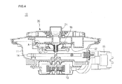
- Fig. 4 is a sectional view taken along line I-I' of Fig. 2;
- Fig. 5 is an exploded perspective view of a filtering assembly of a sump according to an embodiment of the present invention
- Fig. 6 is an exploded perspective view of a self-cleaning filtering assembly according to an embodiment of the present invention.
- Fig. 7 is a bottom view of a sump cover according to an embodiment of the present invention.
- Fig. 8 is a top plane view of a flow guide according to an embodiment of the present invention.
- Fig. 9 is a bottom view of the flow guide of Fig. 8.
- Fig. 10 is a perspective view of a pump housing according to an embodiment of the present invention.
- Fig. 11 is an enlarged view of a portion A of Fig. 4.
- Fig. 12 is a perspective view of a sump case according to an embodiment of the present invention.
- Fig. 1 is a side sectional view of a dishwasher with a sump according to an embodiment of the present invention.
- a dishwasher 1 includes a cabinet 2 defining an outer appearance of the dishwasher 1, a door 4 pivotally coupled to a front surface of the cabinet 2, a tub 3 that is provided in the cabinet 2 to receive dishes, racks removably received in the tub 3, a sump 10 that is mounted on a bottom of the tub 3 to pump out the washing water, a lower nozzle 6 that is mounted on a top surface of the sump 10 to spray the washing water, a water guide 5 that is connected to the sump 10 to guide the washing water to an upper side of the tub 3, an upper nozzle 7 that is rotatable and extends from the water guide 5 to a central portion of the tub 3, and a top nozzle 8 that is connected to an upper end of the water guide 5 to spray the washing water.
- the racks include an upper rack 9b disposed above the upper nozzle 7 and a lower rack 9a disposed above the lower nozzle 6.
- the dishes are arranged on the racks 91 and 9b in a state where the door 4 is opened and a washing mode is selected in a state where the door 4 is closed.
- the washing water is supplied into the sump 10.
- the washing pump mounted in the sump 10 is driven.
- the washing water pumped by the washing pump is alternately fed to the lower nozzle 5 and the water guide 5 by a vario valve (that will be described later).
- the washing water supplied to the water guide 5 is sprayed into the tub through the upper and top nozzles 9b and 8.
- the washing water sprayed through the nozzles collides with surfaces of the dishes to remove food wastes from the dishes.
- the removed food wastes falls to the bottom of the tub.
- the washing process includes a pre-washing process for removing the foreign objects from the dishes, a main washing process in which the washing water containing detergent is sprayed, a drying process for drying the dishes after the main washing process is finished. These processes are sequentially performed.
- the pre-washing and drying process may be optionally omitted by the user.
- Fig. 2 is a perspective view of the sump
- Fig. 3 is an exploded perspective view of the sump
- Fig. 4 is a sectional view taken along line I-I' of Fig. 2.
- the sump includes a sump case 11 for reserving the washing water, a washing pump assembly that is located inside the sump case 11 to pump out the washing water, a filtering assembly 20 coupled to an upper side of the washing pump assembly, a heater 14 that is provided inside the sump case 11 to heat the washing water, a washing motor 13 for driving the washing pump assembly, and a drain motor 15 for draining the washing water stored in the sump case 11.
- the washing pump assembly includes a pump housing 12 provided with a pump case 121 and an impeller 18 that is provided in the pump case 121 to pump out the washing water.
- the washing pump for pumping the washing water is an assembly of he pump case and the impeller.
- a nozzle neck 21 on which the lower nozzle seats is coupled to the filtering assembly 20.
- the water guide 5 is coupled to an edge of the filtering assembly 20.
- a screen filter 17 is coupled to a bottom of the pump housing 12 to filter off foreign objects from the washing water pumped by the washing pump.
- a disposer 16 is mounted under the screen filter 17 to grind the foreign objects contained in the washing water.
- the disposer 16 is connected to a motor shaft. Therefore, the impeller 18 and the disposer 16 rotate together with the motor shaft.
- the sump 10 is comprised of the sump case 11, the washing pump assembly, and the filter assembly 20.
- the filtering assembly 20 includes a self-cleaning filter, a sump cover, and a flow guide provided with a soil chamber, which are integrally coupled to each other through a thermal-bonding process. This will be described in more detail with reference to the accompanying drawings.
- Fig. 5 is an exploded perspective view of the filtering assembly.
- the filtering assembly 20 includes the flow guide 21 for directing the washing water pumped by he washing pump to the lower nozzle and the water guide, the sump cover 22 thermally-bonding to a top surface of the flow guide 21, and the self-cleaning filter 23 thermally-bonding to a top surface of the sump cover 22.
- the soil chamber 211 having a predetermined length is formed on an outer side of the flow guide 21 to collect the food wastes generated during the washing process.
- the soil chamber 211 is connected to the drain pump to drain the food wastes together with the washing water during the drain process.
- the soil chamber 211 is inclined downward toward the end connected to the drain pump so that the food wastes can be fully drained.
- the pump case cover 213 is provided inside the soil chamber 211 and the pump case cover 213 seals an upper portion of the pump case (121 of Fig. 3).
- the vario valve 214 is formed on an end portion of the pump case cover 213.
- a water guide extension 215 and a lower nozzle extension 216 extend from the vario valve cover 214.
- the lower nozzle extension 216 is formed along a top surface of the pump case cover 213.
- a sampling passage 212 is formed on an edge of the pump case cover 213 and connected to the drain pump. That is, the sampling passage 212 is connected to the pump case 121 to divide the flow of the washing water. The washing pump flowing along the sampling passage 212 is collected in the drain pump to back-flow toward the soil chamber in a state where the drain pump does not operation.
- the sump cover 22 thermal-bonding to the top surface of the flow guide 21 is provided with a plurality of water drain holes 221 arranged at a predetermined interval, thereby communicating with the sump case 11. That is, the washing water sprayed through the spraying nozzle is collected in the sump case 11 through the water drain hole 221.
- a separation membrane 222 is formed in the drain hole 221.
- the separation membrane 222 is opened to form a backflow hole 225.
- a lower nozzle connecting portion 224 is formed at a center of the sump cover 22 and the lower nozzle connecting portion 224 is connected to the lower nozzle extension 216 of the flow guide. Therefore, the washing water flowing toward the lower nozzle extension 216 is directed to the lower nozzle through the lower nozzle extension 224.
- a water guide connecting portion 223 is formed on an edge of the sump cover 22.
- the water guide connecting portion 223 communicates with the water guide extension 215 of the flow guide 21. Therefore, the washing water flowing along the water guide extension 215 is directed to the water guide.
- the self-cleaning filter 23 integrally thermal-bonds the top surface of the sump cover 22.
- a net is disposed in the self-cleaning filter 23 to filter off the foreign objects contained in the washing water.
- the structure of the self-cleaning filter 23 will be described in more detail with reference to the accompanying drawings.
- the washing water pumped by the washing pump is alternately supplied to the water guide extension 215 and the lower nozzle extension 216 according to a valve poison of the vario valve.
- a portion of the washing water pumped by the washing pump is branched along the sampling passage 212 and falls toward the drain pump. When the drain pump does not operate, the washing water flows back to the soil chamber 211.
- the washing water flows back through the backflow hole 225 of the sump cover 22.
- a part of the washing water that flows back is distributed on a top surface of the separation membrane 222.
- the foreign objects contained in the washing water are filtered while the washing water passes through the net disposed in the self-cleaning filter 23.
- the purified washing water is collected in the sump case through the water drain hole 221.
- the separation membrane 222 is slightly sloped toward the backflow hole 225 so that the filtered foreign objects can be collected in the soil chamber 211.
- the foreign objects are collected in the soil chamber 211 and exhausted to an external side during the water drain process.
- Fig. 6 is an exploded perspective view of the self-cleaning filtering assembly according to an embodiment of the present invention.
- the self-cleaning filter 23 includes a mesh 232 provided with a plurality of fine apertures, a lower cover 233 provided under the mesh 232, and an upper cover 231 provided above the mesh 232.
- the lower cover 233 thermal-bonds to the upper cover 231 and thus the mesh 232 is fixed between the upper cover 231 and the lower cover 233.
- a plurality of through holes 231b are formed in the upper cover 231.
- a nozzle neck seating portion 231a is formed on a central portion of the upper cover 231.
- a through hole is formed inside the nozzle seating portion 231a to direct the washing water to the lower nozzle.
- a through hole 233c that is identical in a shape to the through hole 231b is formed in the lower cover 233.
- the lower cover 233 is provided with a plurality of mesh fixing ribs 233a and a thermal bonding portion 233b that are formed on inner and outer circumferential edges.
- the method 232 is further provided at the inner and outer circumferential edges with holes 232a through which the mesh fixing ribs 233a penetrate.
- Fig. 7 is a bottom view of the sump cover.
- the thermal-bonding rib 226 that are thermally-bonded to the flow guide 21 is provided on a bottom of the sum cover 22. That is, the shape of the thermal-boding rib 226 corresponds to that of the flow guide 26 so that the inner space of the fluid guide 21 can be completely enclosed and sealed. Therefore, the lower nozzle extension 216 formed on the flow guide 21, the water guide extension 215, and the sampling passage 212 are completely sealed. Therefore, the washing water existing in each space does not leak.
- the backflow hole 225 is formed on an upper portion of the soil chamber 211 so that the washing water supplied through the soil chamber 211 flows back through the backflow hole 225 and there is no leak through the lower nozzle extension 216 and the water guide extension 215.
- An end of the lower nozzle extension 216 communicates with the nozzle connecting portion 224 and an end of the water guide extension 215 communicates with the water guide connecting portion 223.
- At least a portion of the lower nozzle connecting portion 224 formed on a center of the sump cover 22 forms a surface identical to an inner circumferential surface of the end of the lower nozzle extension 216 formed on the flow guide 21. That is, a portion of the lower nozzle connecting portion 224 is formed to correspond to the curvature of the end of the lower nozzle extension 216. Therefore, the inner circumference of the end of the lower nozzle extension 216 and the part of the inner circumference of the lower nozzle connecting portion 224 forms a smooth surface.
- the pressure drop of the washing water pumped to the lower nozzle extension 216 can be prevented.
- the washing water pumped toward the lower nozzle extension 216 forms a rotating flow as it flows through a space formed between the outer circumference of the lower nozzle connecting portion 224 and the inner circumference of the lower nozzle extension 216.
- This rotating flow (washing water) flows back to the vario valve and thus collides with the washing water that is being supplied to the lower nozzle extension 216, thereby forming a turbulent flow.
- the fluid flow resistance is generated near the lower nozzle connecting portion 224 and thus the pressure of the washing water is reduced due to the fluid flow resistance.
- the lower nozzle connecting portion 224 is close-tightly connected to the end of the lower nozzle extension 216.
- Fig. 8 is a top plane view of the flow guide and Fig. 9 is a bottom view of the flow guide.
- the soil chamber 211 is formed along an edge of the flow guide 21.
- a pump case cover 213 is formed in the soil chamber 211.
- a volute rib 213a is formed on a bottom of the pump case cover 213 to cover the inner circumferential edge of the pump case 121 formed on the pump housing 12.
- the volute rib 213a is provided with a sealer pressure rib 213b corresponding to the shape of the pump housing 12.
- the sealer pressure rib 213b is designed to press in a side direction the sealer (10 of FIG. 10) disposed around the outer circumference of the pump housing 12.
- the sealing member disposed around the pump housing is generally designed to be pressed downward by a member seating on the pump housing.
- the sealing member In a case where the sealing member is designed to be pressed downward, if the pressing force is small, the sealing cannot be perfectly realized and thus the washing water may leak.
- the sealer 30 is designed to be pressed in a horizontal direction rather than the vertical direction to prevent the leak of the washing water.
- An operation for supplying the washing water pumped by the washing pump to the nozzles is realized on the bottom of the flow guide 21.
- the washing water is pumped by the washing pump while rotating in a volute shape.
- the vario valve is located on a discharge portion of the washing pump to selectively direct the washing water to the lower nozzle or the water guide.
- the flow guide 21 is provided with a vario valve cover 214 for supporting a top surface of the vario valve.
- the water guide extension 215 and the lower nozzle extension 216 extend from the vario valve cover 214.
- the water guide extension 215 is formed to be almost in parallel with the washing water flow direction discharged from the washing pump. This is to minimize the flow loss as the washing valve passes through the vario valve.
- the lower nozzle extension 216 is carved in a direction identical to the rotation direction of the washing water rotating in the washing pump.
- the washing water rotates in an arrow direction and is discharged from the washing pump toward the vario valve.
- the washing water directed to the water guide straightly flows from the discharge hole of the washing pump.
- the washing water directed to the lower nozzle flows along the lower nozzle extension 216 curved in a direction identical to the rotational direction of the washing water in the washing pump. Accordingly, even when the flow direction of the washing water is switched by the vario valve, the flow loss can be reduced by the above-described passage structure.
- the inner circumference of the lower nozzle extension 224 formed on a central portion of the sump cover 22 is coplanar to the inner circumference of the end of the nozzle extension 216. This will be described in more detail later.
- the sampling hole 217 is formed on the edge of the pump case cover 213 forming the flow guide 21. That is, the pump caver cover 213 covers the pump case 121 formed inside the pump housing 12. Therefore, a part of the washing water rotating in the pump case 121 ascends through the sampling hole 217 and flows along the sampling passage 212.
- An end of the sampling passage 212 communicates with a drain pump connection tube 218.
- the drain pump connection tube 218 extends from the flow guide 21 downward by a predetermined length and is connected to the drain pump case.
- the membrane is formed in the drain pump connection tube 218 to be divided from the drain hole 218a as the backflow hole 218b.
- An end of the sampling passage 212 is connected to the drain hole 218a and an end of the soil chamber 211 is connected to the backflow hole 218b.
- the washing water branched off along the sampling passage 212 falls to the drain pump through the drain hole 218a.
- the washing water falling to the drain pump flows back through the backflow hole 218b and flows to soil chamber 211.
- a backflow side end of the soil chamber 211 is lower than an opposite end thereof and thus the food wastes and washing water accumulated in the soil chamber 211 are drained together during the draining process.
- Fig. 10 is a perspective view of the pump housing.
- the pump housing 12 is disposed inside the sump case 11 and coupled thereto by a fastener such as a screw.
- the pump housing 12 is provided at the outer circumference with a plurality of fixing legs 124 that will be fixed on the sump case 11.
- the fixing leg 124 is provided at an end with a hole in which a fixing boss will be inserted.
- the pump housing 12 is provided at an outer circumference with a flow guide fixing boss 125 that is inserted into the flow guide 21.
- the pump housing 12 is securely fixed on the bottom of the flow guide 21 by the coupling member inserted into the flow guide fixing boss 125.
- the pump cases 121 is formed with a volute shape in the pump housing 12.
- the screen filter (17 of Fig. 3) is coupled to a lower end of the suction hole 122 so that the washing water is introduced into the pump case 121 after the foreign objects of the washing water is primarily filtered.
- the pump case 121 is provided at a discharge side with a vario valve seating portion 127 on which the vario valve (19 of Fig. 3) seats.
- a water guide extension passage 128a and a lower nozzle guide extension passage 128b extend from the vario valve seating portion 127.
- the water guide extension passage 128a straightly extends from a discharge hole of the pump case 121.
- the lower nozzle guide passage 128b is curved in a direction identical to the rotational direction of the washing water in the pump case 121.
- a sealing seating portion on which the sealer 30 seats is formed on the outer circumference of the pump housing 12.
- a volute rib seating portion 129 is formed on upper edges of the pump case 121, vario valve seating portion 127, and water guide extension passage 128a, lower nozzle extension passage 128b with predetermined steps to form a closed-circle.
- a bottom surface of the pump case 121 is formed at an identical level with a bottom surface of the discharge portion of the pump case 121 to uniformly maintain the washing water pressure.
- the washing water pressure is reduced.
- the vario valve 19 is provided in the pump housing 12 having the pump case 121, only the through hole through which the valve shaft of the vario valve penetrates is formed on the bottom surface of the vario valve seating portion 127 and the discharge portion of the pump case 121, the water guide extension passage 128a and the lower nozzle extension passage 188b are integrally formed with the vario valve seating portion 127. As a result, the washing water discharged from the pump case 121 does not leak through the outer circumference of the vario valve 19 during the direction of the washing water to the water guide extension passage 128a or the lower nozzle extension passage 128b.
- Fig. 11 is an enlarged view of a portion A of Fig. 4.
- the sealer seating portion 126 is formed on the outer circumference of the pump housing 12 with a step.
- the sealer pressing rib 213b extending from the bottom of the flow guide 21 closely contacts the outer circumference of the pump housing 12.
- the sealer 30 occupies the space defined between the sealer pressing rib 213b and the sealer seating portion 126.
- the volute rib seating portion 129 is formed on an inner circumferential edge of the pump case with a step.
- the volute rib 213a extending from the bottom of the flow guide 21 seats on the volute rib seating portion 129.
- a separate sealing member may be interposed between the volute rib 21a and the volute rib seating portion 12.
- the volute rib 213a presses an inner side surface or a top surface of the sealing member seating on the volute rib seating portion 129 to prevent the washing water from leaking.
- the sealer 30 is disposed around the outer circumferential edge of the pump housing 12 and the pressed in the side direction by the sealer pressing rib 213b, the leak of the washing water rotating in the pump case 121 can be prevented.
- the leak of the washing water in the pump case 121 is primarily prevented by the volute rib 213a, secondarily prevented by the sealer 30, and thirdly prevented by the sealer pressing rib 213b.
- the washing water may be very likely to leak through a gap between the sealer 30 and the pump housing 12 or between the sealer 30 and the flow guide 21.
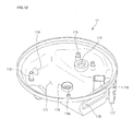
- Fig. 12 is a perspective view of the sump case.
- a water storing portion 111 is formed in the sump case 11.
- the sump case 11 is provided with first and second fixing bosses 112 and 113 for fixing the pump housing 12.
- the first fixing boss 112 penetrates the fixing leg 124 of the pump housing 12 and the second fixing boss 113 is coupled to the bottom surface of the pump housing 12 opposite to the fixing leg 124.
- the sump case 11 is provided at a bottom surface with a motor shaft penetration hole 119a through which a motor shaft of the washing motor penetrates.
- a cylindrical motor sealer seating portion 119 extends around the motor shaft penetration hole 119a.
- a circular sealing member is inserted in the motor sealer seating portion 119 to prevent the washing water from leaking through the motor shaft.
- a water supply hole 114 is formed on a side of the sump case 11 and a drain pump case 117 is provided on another side of the sump case 11. That is, a drain impeller is received in the drain pump case 117 and the drain pump impeller is connected to the drain motor 15 (see Fig. 3).
- a heater insertion hole 118 is formed on another side of the sump case 11.
- a vario valve shaft penetration hole 115 is formed on a side of the bottom surface of the sump case 11. Therefore, the shaft of the vario valve 19 penetrates the sump case 11 and is connected to the vario motor attached on the bottom surface of the case 11.
- a drain guide 116 is provided inside the sump case 11 where the drain pump case 117 is formed.
- a drain pump connection tube (218 of Fig. 8) extending from the bottom of the flow guide 21 is fitted in the drain guide 116. Therefore, the washing water falling through the drain hole 218a of the drain pump connection tube 218 is directed to the drain pump case by the drain guide 116.
- the washing water collected in the drain pump case 117 flows back along the drain guide 116 and is then directed to the soil chamber 211 through the backflow hole 218b of the drain pump connection tube 218.
- a drain hole (not shown) is formed on a lower end of the drain guide 116 and communicates with the water storing portion 111 of the sump case 11.
- a check valve is installed in the drain hole to prevent the washing water collected in the drain pump case 117 flows back to the water storing portion 111.
- the washing water and the food wastes stored in the soil chamber 211 and the water storing portion 111 are simultaneously directed to the drain pump case 117 through the drain guide 116 and then discharged to the external side by the operation of the drain impeller.
Landscapes
- Engineering & Computer Science (AREA)
- Water Supply & Treatment (AREA)
- Structures Of Non-Positive Displacement Pumps (AREA)
- Washing And Drying Of Tableware (AREA)
Applications Claiming Priority (1)
| Application Number | Priority Date | Filing Date | Title |
|---|---|---|---|
| KR1020060093858A KR20080028521A (ko) | 2006-09-27 | 2006-09-27 | 식기 세척기의 섬프 |
Publications (2)
| Publication Number | Publication Date |
|---|---|
| EP1905340A2 true EP1905340A2 (de) | 2008-04-02 |
| EP1905340A3 EP1905340A3 (de) | 2010-01-13 |
Family
ID=38947359
Family Applications (1)
| Application Number | Title | Priority Date | Filing Date |
|---|---|---|---|
| EP07102037A Withdrawn EP1905340A3 (de) | 2006-09-27 | 2007-02-09 | Sammelbehälter für eine Geschirrspülmaschine |
Country Status (5)
| Country | Link |
|---|---|
| US (1) | US20080072934A1 (de) |
| EP (1) | EP1905340A3 (de) |
| KR (1) | KR20080028521A (de) |
| CN (1) | CN101152071B (de) |
| CA (1) | CA2576001A1 (de) |
Cited By (1)
| Publication number | Priority date | Publication date | Assignee | Title |
|---|---|---|---|---|
| ITTO20100267A1 (it) * | 2010-04-08 | 2011-10-09 | Bitron Spa | Macchina lavastoviglie con pozzetto perfezionato |
Families Citing this family (16)
| Publication number | Priority date | Publication date | Assignee | Title |
|---|---|---|---|---|
| KR100640797B1 (ko) * | 2005-01-12 | 2006-11-06 | 엘지전자 주식회사 | 식기 세척기의 구동부 |
| KR101484621B1 (ko) * | 2008-04-11 | 2015-01-20 | 엘지전자 주식회사 | 식기세척기 |
| US8424546B2 (en) * | 2008-07-15 | 2013-04-23 | Electrolux Home Products, Inc. | Sump assembly for a dishwasher, and associated method |
| KR101507803B1 (ko) * | 2008-08-21 | 2015-04-03 | 엘지전자 주식회사 | 식기 세척기 |
| KR20100052217A (ko) * | 2008-11-10 | 2010-05-19 | 엘지전자 주식회사 | 식기 세척기 |
| KR20100067571A (ko) * | 2008-12-11 | 2010-06-21 | 삼성전자주식회사 | 식기세척기 |
| US8888931B2 (en) * | 2010-12-14 | 2014-11-18 | General Electric Company | Dishwasher pump inlet macerator system |
| US9655494B2 (en) | 2014-06-05 | 2017-05-23 | Wolf Appliance, Inc. | Dishwasher filtration system |
| USD776372S1 (en) | 2014-06-05 | 2017-01-10 | Wolf Appliance, Inc. | Dishwasher tub bottom |
| CN106321898B (zh) * | 2015-07-02 | 2019-05-17 | 青岛海尔洗碗机有限公司 | 一种分水阀组件及洗碗机 |
| CN105877665B (zh) * | 2016-06-29 | 2020-08-25 | 苏州喜多多机械科技有限公司 | 洗碗机 |
| USD840117S1 (en) | 2016-09-23 | 2019-02-05 | Wolf Appliance, Inc. | Dishwasher water softener cap |
| USD842558S1 (en) | 2016-09-23 | 2019-03-05 | Wolf Appliance, Inc. | Dishwasher filter cap |
| CN112690738A (zh) * | 2021-01-19 | 2021-04-23 | 漯河市紫新商贸有限公司 | 一种厨具用烘干装置 |
| CN114951185B (zh) * | 2022-05-27 | 2023-04-21 | 苏州天准科技股份有限公司 | 具有自动喷射酒精的擦拭装置 |
| DE102024204537A1 (de) * | 2024-05-16 | 2025-11-20 | BSH Hausgeräte GmbH | Siebsystem und Haushalts-Geschirrspülmaschine |
Family Cites Families (13)
| Publication number | Priority date | Publication date | Assignee | Title |
|---|---|---|---|---|
| US3521451A (en) * | 1968-08-13 | 1970-07-21 | American Standard Inc | Fluid coupling using water |
| DE2602065B2 (de) * | 1976-01-21 | 1978-11-09 | Bosch-Siemens Hausgeraete Gmbh, 7000 Stuttgart | Geschirrspülmaschine |
| US4404006A (en) * | 1981-06-19 | 1983-09-13 | Williams Charles D | Filter device |
| US4730630A (en) * | 1986-10-27 | 1988-03-15 | White Consolidated Industries, Inc. | Dishwasher with power filtered rinse |
| US6182674B1 (en) * | 1996-11-19 | 2001-02-06 | Whirlpool Corporation | Pump and soil collection system for a dishwasher |
| KR100529879B1 (ko) * | 2002-11-28 | 2005-11-22 | 엘지전자 주식회사 | 식기세척기의 필터 청소장치 |
| KR100606823B1 (ko) * | 2004-05-28 | 2006-08-01 | 엘지전자 주식회사 | 식기 세척기의 집수장치 |
| KR101052964B1 (ko) * | 2004-06-24 | 2011-07-29 | 엘지전자 주식회사 | 식기 세척기의 모터 고정 구조 |
| CN101884521B (zh) * | 2004-09-17 | 2011-12-07 | Lg电子株式会社 | 洗碗机 |
| KR100772224B1 (ko) * | 2004-12-07 | 2007-11-01 | 엘지전자 주식회사 | 식기 세척기의 섬프 구조 |
| KR101138135B1 (ko) * | 2004-12-07 | 2012-04-23 | 엘지전자 주식회사 | 식기 세척기의 자정 필터 조립 구조 |
| KR100640797B1 (ko) * | 2005-01-12 | 2006-11-06 | 엘지전자 주식회사 | 식기 세척기의 구동부 |
| US7985300B2 (en) * | 2005-04-04 | 2011-07-26 | Lg Electronics Inc. | Dishwasher and assembly method thereof |
-
2006
- 2006-09-27 KR KR1020060093858A patent/KR20080028521A/ko not_active Ceased
-
2007
- 2007-01-26 CA CA002576001A patent/CA2576001A1/en not_active Abandoned
- 2007-02-02 US US11/701,432 patent/US20080072934A1/en not_active Abandoned
- 2007-02-09 EP EP07102037A patent/EP1905340A3/de not_active Withdrawn
- 2007-02-16 CN CN2007100841219A patent/CN101152071B/zh not_active Expired - Fee Related
Cited By (2)
| Publication number | Priority date | Publication date | Assignee | Title |
|---|---|---|---|---|
| ITTO20100267A1 (it) * | 2010-04-08 | 2011-10-09 | Bitron Spa | Macchina lavastoviglie con pozzetto perfezionato |
| WO2011125027A1 (en) * | 2010-04-08 | 2011-10-13 | Bitron S.P.A. | Dishwashing machine |
Also Published As
| Publication number | Publication date |
|---|---|
| EP1905340A3 (de) | 2010-01-13 |
| US20080072934A1 (en) | 2008-03-27 |
| KR20080028521A (ko) | 2008-04-01 |
| CN101152071B (zh) | 2012-05-30 |
| CN101152071A (zh) | 2008-04-02 |
| CA2576001A1 (en) | 2008-03-27 |
Similar Documents
| Publication | Publication Date | Title |
|---|---|---|
| EP1905340A2 (de) | Sammelbehälter für eine Geschirrspülmaschine | |
| US20080149148A1 (en) | Sump of dishwasher | |
| US9060667B2 (en) | Sump of dishwasher | |
| CA2575941C (en) | Sump for dishwasher | |
| US8449690B2 (en) | Sump of dish washer | |
| CN101164489B (zh) | 洗碗机的水槽 | |
| JP2008513092A (ja) | 食器洗い機 | |
| US20060118148A1 (en) | Soil jam preventing structure of dish washer | |
| US7644718B2 (en) | Sump of dish washer | |
| US20060118147A1 (en) | Sump of dish washer | |
| US20060118145A1 (en) | Dish washer and sump mounting structure thereof | |
| KR100772229B1 (ko) | 식기 세척기의 섬프 | |
| KR100772228B1 (ko) | 식기 세척기의 섬프 | |
| US7771543B2 (en) | Leakage preventing structure of dish washer | |
| KR101138135B1 (ko) | 식기 세척기의 자정 필터 조립 구조 | |
| US8622065B2 (en) | Dish washer | |
| US20060180184A1 (en) | Sump of dishwasher |
Legal Events
| Date | Code | Title | Description |
|---|---|---|---|
| PUAI | Public reference made under article 153(3) epc to a published international application that has entered the european phase |
Free format text: ORIGINAL CODE: 0009012 |
|
| AK | Designated contracting states |
Kind code of ref document: A2 Designated state(s): AT BE BG CH CY CZ DE DK EE ES FI FR GB GR HU IE IS IT LI LT LU LV MC NL PL PT RO SE SI SK TR |
|
| AX | Request for extension of the european patent |
Extension state: AL BA HR MK YU |
|
| PUAL | Search report despatched |
Free format text: ORIGINAL CODE: 0009013 |
|
| AK | Designated contracting states |
Kind code of ref document: A3 Designated state(s): AT BE BG CH CY CZ DE DK EE ES FI FR GB GR HU IE IS IT LI LT LU LV MC NL PL PT RO SE SI SK TR |
|
| AX | Request for extension of the european patent |
Extension state: AL BA HR MK RS |
|
| AKY | No designation fees paid | ||
| STAA | Information on the status of an ep patent application or granted ep patent |
Free format text: STATUS: THE APPLICATION IS DEEMED TO BE WITHDRAWN |
|
| 18D | Application deemed to be withdrawn |
Effective date: 20100714 |
|
| REG | Reference to a national code |
Ref country code: DE Ref legal event code: 8566 |