EP1905347A2 - Appareil d'endoscope électronique - Google Patents
Appareil d'endoscope électronique Download PDFInfo
- Publication number
- EP1905347A2 EP1905347A2 EP07019051A EP07019051A EP1905347A2 EP 1905347 A2 EP1905347 A2 EP 1905347A2 EP 07019051 A EP07019051 A EP 07019051A EP 07019051 A EP07019051 A EP 07019051A EP 1905347 A2 EP1905347 A2 EP 1905347A2
- Authority
- EP
- European Patent Office
- Prior art keywords
- image
- spectral
- color
- wavelength
- electronic endoscope
- Prior art date
- Legal status (The legal status is an assumption and is not a legal conclusion. Google has not performed a legal analysis and makes no representation as to the accuracy of the status listed.)
- Withdrawn
Links
- 230000003595 spectral effect Effects 0.000 claims abstract description 82
- 239000011159 matrix material Substances 0.000 claims abstract description 29
- 239000003086 colorant Substances 0.000 claims abstract description 23
- 238000003384 imaging method Methods 0.000 claims abstract description 11
- 230000001131 transforming effect Effects 0.000 description 20
- 238000006243 chemical reaction Methods 0.000 description 16
- 101000860173 Myxococcus xanthus C-factor Proteins 0.000 description 10
- 230000000875 corresponding effect Effects 0.000 description 10
- 238000012545 processing Methods 0.000 description 10
- 238000009877 rendering Methods 0.000 description 7
- 210000001519 tissue Anatomy 0.000 description 7
- 230000006870 function Effects 0.000 description 5
- 210000004204 blood vessel Anatomy 0.000 description 4
- 238000005286 illumination Methods 0.000 description 4
- 230000035945 sensitivity Effects 0.000 description 4
- 238000000034 method Methods 0.000 description 3
- 238000003825 pressing Methods 0.000 description 3
- UPYKUZBSLRQECL-UKMVMLAPSA-N Lycopene Natural products CC(=C/C=C/C=C(C)/C=C/C=C(C)/C=C/C1C(=C)CCCC1(C)C)C=CC=C(/C)C=CC2C(=C)CCCC2(C)C UPYKUZBSLRQECL-UKMVMLAPSA-N 0.000 description 2
- 239000008280 blood Substances 0.000 description 2
- 210000004369 blood Anatomy 0.000 description 2
- 150000001746 carotenes Chemical class 0.000 description 2
- 235000005473 carotenes Nutrition 0.000 description 2
- 238000004891 communication Methods 0.000 description 2
- 230000002596 correlated effect Effects 0.000 description 2
- 239000006185 dispersion Substances 0.000 description 2
- 238000012986 modification Methods 0.000 description 2
- 230000004048 modification Effects 0.000 description 2
- 210000004798 organs belonging to the digestive system Anatomy 0.000 description 2
- 238000005070 sampling Methods 0.000 description 2
- 238000001228 spectrum Methods 0.000 description 2
- NCYCYZXNIZJOKI-UHFFFAOYSA-N vitamin A aldehyde Natural products O=CC=C(C)C=CC=C(C)C=CC1=C(C)CCCC1(C)C NCYCYZXNIZJOKI-UHFFFAOYSA-N 0.000 description 2
- INGWEZCOABYORO-UHFFFAOYSA-N 2-(furan-2-yl)-7-methyl-1h-1,8-naphthyridin-4-one Chemical compound N=1C2=NC(C)=CC=C2C(O)=CC=1C1=CC=CO1 INGWEZCOABYORO-UHFFFAOYSA-N 0.000 description 1
- 108010054147 Hemoglobins Proteins 0.000 description 1
- 102000001554 Hemoglobins Human genes 0.000 description 1
- 235000000177 Indigofera tinctoria Nutrition 0.000 description 1
- 108010064719 Oxyhemoglobins Proteins 0.000 description 1
- 238000000701 chemical imaging Methods 0.000 description 1
- ZXJXZNDDNMQXFV-UHFFFAOYSA-M crystal violet Chemical compound [Cl-].C1=CC(N(C)C)=CC=C1[C+](C=1C=CC(=CC=1)N(C)C)C1=CC=C(N(C)C)C=C1 ZXJXZNDDNMQXFV-UHFFFAOYSA-M 0.000 description 1
- 108010002255 deoxyhemoglobin Proteins 0.000 description 1
- 238000010586 diagram Methods 0.000 description 1
- 238000011156 evaluation Methods 0.000 description 1
- 230000002496 gastric effect Effects 0.000 description 1
- 229940097275 indigo Drugs 0.000 description 1
- COHYTHOBJLSHDF-UHFFFAOYSA-N indigo powder Natural products N1C2=CC=CC=C2C(=O)C1=C1C(=O)C2=CC=CC=C2N1 COHYTHOBJLSHDF-UHFFFAOYSA-N 0.000 description 1
- 210000002429 large intestine Anatomy 0.000 description 1
- 239000004973 liquid crystal related substance Substances 0.000 description 1
- 210000004400 mucous membrane Anatomy 0.000 description 1
- 210000002784 stomach Anatomy 0.000 description 1
- 230000001360 synchronised effect Effects 0.000 description 1
- 230000017105 transposition Effects 0.000 description 1
- 239000013598 vector Substances 0.000 description 1
Images



Classifications
-
- A—HUMAN NECESSITIES
- A61—MEDICAL OR VETERINARY SCIENCE; HYGIENE
- A61B—DIAGNOSIS; SURGERY; IDENTIFICATION
- A61B1/00—Instruments for performing medical examinations of the interior of cavities or tubes of the body by visual or photographical inspection, e.g. endoscopes; Illuminating arrangements therefor
- A61B1/06—Instruments for performing medical examinations of the interior of cavities or tubes of the body by visual or photographical inspection, e.g. endoscopes; Illuminating arrangements therefor with illuminating arrangements
- A61B1/0638—Instruments for performing medical examinations of the interior of cavities or tubes of the body by visual or photographical inspection, e.g. endoscopes; Illuminating arrangements therefor with illuminating arrangements providing two or more wavelengths
-
- A—HUMAN NECESSITIES
- A61—MEDICAL OR VETERINARY SCIENCE; HYGIENE
- A61B—DIAGNOSIS; SURGERY; IDENTIFICATION
- A61B1/00—Instruments for performing medical examinations of the interior of cavities or tubes of the body by visual or photographical inspection, e.g. endoscopes; Illuminating arrangements therefor
- A61B1/00002—Operational features of endoscopes
- A61B1/00043—Operational features of endoscopes provided with output arrangements
- A61B1/00045—Display arrangement
- A61B1/0005—Display arrangement combining images e.g. side-by-side, superimposed or tiled
-
- A—HUMAN NECESSITIES
- A61—MEDICAL OR VETERINARY SCIENCE; HYGIENE
- A61B—DIAGNOSIS; SURGERY; IDENTIFICATION
- A61B1/00—Instruments for performing medical examinations of the interior of cavities or tubes of the body by visual or photographical inspection, e.g. endoscopes; Illuminating arrangements therefor
- A61B1/06—Instruments for performing medical examinations of the interior of cavities or tubes of the body by visual or photographical inspection, e.g. endoscopes; Illuminating arrangements therefor with illuminating arrangements
- A61B1/0646—Instruments for performing medical examinations of the interior of cavities or tubes of the body by visual or photographical inspection, e.g. endoscopes; Illuminating arrangements therefor with illuminating arrangements with illumination filters
-
- A—HUMAN NECESSITIES
- A61—MEDICAL OR VETERINARY SCIENCE; HYGIENE
- A61B—DIAGNOSIS; SURGERY; IDENTIFICATION
- A61B5/00—Measuring for diagnostic purposes; Identification of persons
- A61B5/0059—Measuring for diagnostic purposes; Identification of persons using light, e.g. diagnosis by transillumination, diascopy, fluorescence
- A61B5/0075—Measuring for diagnostic purposes; Identification of persons using light, e.g. diagnosis by transillumination, diascopy, fluorescence by spectroscopy, i.e. measuring spectra, e.g. Raman spectroscopy, infrared absorption spectroscopy
-
- A—HUMAN NECESSITIES
- A61—MEDICAL OR VETERINARY SCIENCE; HYGIENE
- A61B—DIAGNOSIS; SURGERY; IDENTIFICATION
- A61B5/00—Measuring for diagnostic purposes; Identification of persons
- A61B5/0059—Measuring for diagnostic purposes; Identification of persons using light, e.g. diagnosis by transillumination, diascopy, fluorescence
- A61B5/0082—Measuring for diagnostic purposes; Identification of persons using light, e.g. diagnosis by transillumination, diascopy, fluorescence adapted for particular medical purposes
- A61B5/0084—Measuring for diagnostic purposes; Identification of persons using light, e.g. diagnosis by transillumination, diascopy, fluorescence adapted for particular medical purposes for introduction into the body, e.g. by catheters
- A61B5/0086—Measuring for diagnostic purposes; Identification of persons using light, e.g. diagnosis by transillumination, diascopy, fluorescence adapted for particular medical purposes for introduction into the body, e.g. by catheters using infrared radiation
Definitions
- the present invention relates to electronic endoscope apparatuses, and more particularly to an electronic endoscope apparatus capable of forming and displaying a spectral image (video image) at a particular wavelength band by operation-processing an image signal carrying a subject color image.
- matrix data coefficient sets
- spectral-image signal presuming a spectral image obtained by operating the matrix data with RGB signals through a narrow band-pass filter.
- a spectral image is configured to be displayed as a monochromatic image or as a color image based on particular three colors previously designated.
- the region on display is possibly in a color different from the real one. In this respect, annoyance is to be felt by a physician not accustomed to using the apparatus.
- An object of an illustrative, non-limiting embodiment of the invention is to an electronic endoscope apparatus arranged to obtain a spectral image by an operation, in which a spectral image in a region can be displayed similar in hue to the real one.
- an electronic endoscope apparatus comprising: a light source that illuminates a subject with white light; a color imaging device that takes an image of the subject illuminated with white light; and a spectral-image forming circuit that operates RGB three color image signals based on an output from the color imaging device and a matrix data to generate an spectral image signal representative of a spectral image in a color at a designated wavelength, wherein the spectral-image forming circuit is adapted to generate spectral image signals representative of spectral images in respective colors at least three wavelengths different from one another.
- the three wavelengths are preferably wavelengths at red, green and blue portions of light.
- the matrix data for generating the spectral-image signal representative of the spectral image in the color at the designated wavelength can be prepared and stored in a storage section in advance.
- the spectral-image forming circuit may be adapted to be capable of generating a spectral-image signal representative of a spectral image in a fixed colors so as to selectively output the signal representative of the spectral image in the fixed color and the spectral image signal representative of the spectral image in the color of the designated wavelength.
- An electronic endoscope apparatus is configured to generate spectral-image signals as to at least three wavelengths different one from another. Accordingly, based on the spectral-image signals, a color spectral image can be formed. Those spectral-image signals are given as signals representing spectral images in colors at designated wavelengths. Accordingly, a spectral image, displayed on a display or to be recorded at an image recorder depending upon the spectral-image signals, is to represent the region taken an image of by a color imaging device basically identically in hue to the real one.
- operation processing can be performed swiftly to display or record a spectral image.
- a spectral image can be desirably selectably displayed or recorded identically in hue to the real one or displayed or recorded in fixed hue, in accordance with the requirement of a physician or the like.
- Fig. 1 shows a basic configuration of an electronic endoscope apparatus according to an exemplary embodiment of the invention.
- the electronic endoscope apparatus of the embodiment is to be set in any of a mode to display a subject spectral image formed as referred later, and a mode to display a subject ordinary image.
- the spectral-image display mode setting is selectively available in any one of a mode to display a spectral image as a color image based on fixed three color-image signals and a mode to display a color image showing a subject in a hue as per (approximate to) the actual.
- explanation is made on the spectral-image display mode and the configuration for realizing same.
- the electronic endoscope apparatus is constructed with a scope 10, i.e. an endoscope main body, and a processor unit 12 detachably connected with the scope 10.
- the processor unit 12 is arranged therein with a light source 14 that emits white light.
- An illumination window 23 is provided at a tip of the scope 10.
- the illumination window 23 is opposed with one end of a light guide 24 the other end of which is connected to the light source 14.
- the light source 14 may be arranged separately from the processor unit 12.
- a CCD, or solid-state imaging device, 15 is provided at a tip of the scope 10.
- the CCD 15 uses a complementary-color type having Mg (magenta), Ye (yellow) and Cy (cyan) color filters or a primary-color type having RGB color filters at the image surface.
- the CCD 15 is connected with a CCD drive circuit 16 that forms a drive pulse depending upon a synchronization signal, and a CDS/AGC (correlated double sampling/auto gain control) circuit 17 that samples and amplifies the image (video) signal outputted from the CCD 15.
- the CDS/AGC circuit 17 is connected with an A/D converter 18 that digitizes the analog output thereof.
- a microcomputer 20 is provided to control the various circuits provided therein and take communication control with the processor unit 12.
- a DSP (digital signal processor) 25 is provided to perform various image processes on the image signal digitized at the A/D converter 18. From the image signal, the DSP 25 is to generate and output a Y/C signal constituted by luminance (Y) and color difference [C(R - Y, B - Y)] signals.
- the DSP 25 is connected with a first conversion circuit 28.
- the first color-conversion circuit 28 is to convert the Y/C signal outputted from the DSP 25 into R, G and B three color-image signals. Note that the DSP 25 may be arranged on the scope 10 side.
- a color-space transforming circuit 29 that performs matrix operation for forming a spectral image and outputs image signals representative of spectral images at selected wavelength bands ⁇ 1, ⁇ 2, ⁇ 3, a mode selector 30 that selects any of a single-color mode to form a spectral image at one narrow wavelength band and a three-color mode to form a spectral image at three wavelength bands, a second color-conversion circuit 31 that inputs image signals ⁇ 1s, ⁇ 2s, ⁇ 3s at one or three wavelength bands as signals Rs, Gs, Bs in order to perform a process corresponding to RGB signals and converts the signals Rs, Gs, Bs into a Y/C signal, a signal processing circuit 32 that performs signal processing including mirror image processing, mask generation and character generation, and a D/A converter 33.
- the D/A converter 33 in the last stage, is connected to the outside of the processor unit 12, e.g. a monitor 34 made by a liquid-crystal display, a CRT or the like and to an image recorder 45 made by a light-scanning recorder.
- a monitor 34 made by a liquid-crystal display, a CRT or the like
- an image recorder 45 made by a light-scanning recorder.
- two-color mode may be established to form a spectral image at two wavelength bands.
- a microcomputer 35 having a function to have communications with the scope 10, to control the circuits of the processor unit 12 and to input the matrix (coefficient) data stored in a memory 36 to the color-space transforming circuit 29 or so.
- the memory 36 is stored with matrix data in a table form to form a spectral image based upon RGB signals.
- the matrix data stored in the memory 36 is exemplified as in Table 1.
- the matrix data in Table 1 is constituted with sixty-one wavelength parameters (coefficient sets) p1 - p61 obtained by segmenting the wavelength range of 400 to 700 nm at an interval of 5 nm and parameters P1 - P3 for forming an ordinary image.
- matrix operation is performed by using, as coefficients (k pr , k pg , k pb ), the coefficients (-0.00119, 0.002346, 0.0016) of the parameter p21 corresponding to the center wavelength 500 nm, the coefficients (0.004022, 0.000068, -0.00097) of the parameter p45 corresponding to the center wavelength 620 nm and the coefficients (0.005152, -0.00192, -0.000088) of the parameter p51 corresponding to the center wavelength 650 nm, of among the sixty-one parameters in Table 1.
- the color-space transforming circuit 29 performs matrix operation by use of the coefficients of parameters P1 - P3 when instructed to display or record an ordinary image.
- the RGB signals outputted from the first color-conversion circuit 28 are outputted, as they are, from the color-space transforming circuit 29.
- the microcomputer 35 is connected with an operation panel 41, an image record controller 42, and an input potion 43 such as a keyboard, in addition to the memory 36.
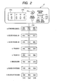
- Fig. 2 illustrates in detail the operation panel 41.
- the operation panel 41 is provided with a set select switch 41 a for selecting any of wavelength sets a - h schematically shown together therewith, a wavelength select switch 41b for selecting respective center wavelengths of wavelength bands ⁇ 1, ⁇ 2, ⁇ 3, a change-interval setting switch 41c for setting an interval of wavelength to be changed by the wavelength select switch 41b, a single-three color mode change switch for switching between single-color mode and three-color mode as mentioned before, and a spectral-image forming switch 41j for giving an instruction to form a spectral image.
- the spectral-image forming switch 41j can be provided on the scope 10 side. Meanwhile, although a fixed-color mode switch 41e and a real-color mode switch 41f are provided in a position lower than the spectral-image forming switch 41j, those will be referred later.
- the light source 14 shown in Fig. 1 is driven to emit white light into the light guide 24.
- the white light exiting at the light guide 24 arranged within the scope 10, is illuminated to a subject.
- the CCD 15, driven by the CCD drive circuit 16, takes an image of the subject and outputs an image signal.
- the image signal is subjected to correlated double sampling and auto gain control at the CDS/AGC circuit 17, and then A/D-converted at the A/D converter, thus being inputted as a digital signal to the DSP 25 of the processor unit 12.
- gamma processing is made on the output signal of from the scope 10 while color conversion is made on the signals obtained through the Mg, Ye, Cy and g color filters, to form a Y/C signal as noted before.
- the Y/C signal, outputted from the DSP 25, is inputted to the first color-conversion circuit 28 where it is converted into an RGB signals.
- the RGB signals are inputted to the color-space transforming circuit 29.
- matrix operation is performed based on the RGB signals and the matrix data, in order to form a spectral image.
- the color-space transforming circuit 29 When pressing the spectral-image forming switch 41j of the fig. 2 operation panel 41, the color-space transforming circuit 29 performs matrix operation, for forming a spectral image, according to the equation 1 by use of the matrix data stored in the memory 36 together with the pixel-based RGB signals. Namely, in this case, three wavelength bands ⁇ 1, ⁇ 2, ⁇ 3 are established by the operation on the operation panel 41 so that the microcomputer 35 can read the matrix data corresponding to the selected three wavelength bands out of the memory 36 and then input those to the color-space transforming circuit 29.
- the spectral image signals ⁇ 1s, ⁇ 2s, ⁇ s are respectively inputted as three color image signals Rs, Gs, Bs to the second color-conversion circuit 31.
- any one of the spectral image signals ⁇ 1s, ⁇ 2s, ⁇ s is inputted as a signal Rs, Gs, Bs to the second color-conversion circuit 31.
- the three-color image signals Rs, Gs, Bs are converted into a Y/C signal (Y, Rs - Y, Bs - Y).
- the Y/C signal is inputted to the monitor 34 and image recorder 45 through the signal processing circuit 32 and D/A converter 33.
- the monitor 34 Based on the Y/C signal, the monitor 34 displays a spectral image given as a color image constituted by color components at wavelength bands as shown in Figs. 4 and 5.
- Fig. 4 is a concept figure showing a superposition of the three wavelength bands ⁇ 1, ⁇ 2, ⁇ 3, for forming a spectral image, over color-filter spectral sensitivity characteristics R, G, B of the primary-color CCD 15.
- Fig. 5 is a concept figure showing a superposition of the three wavelength bands ⁇ 1, ⁇ 2, ⁇ 3 over a reflection spectrum of from a living body.
- the spectral image signals ⁇ 1s, ⁇ 2s, ⁇ 3s, based on the exemplified parameters p21, p45, p51, represent a spectral image having a wavelength band in a range of within ⁇ 10 nm respectively about 500 nm, 620 nm and 650 nm, as shown in Fig. 5.
- the three signals, in a combination, constitute a color spectral image (moving or still image) that is to be displayed or recorded.
- the color spectral image is given as a color image based on fixed three color-image signals.
- the real-color mode switch 41f shown in Fig .2 is pressed, a color image of a subject is displayed or to be recorded in a real color (in a color approximate to the actual), explanation will be made in detail later in respect of this point.
- the Fig. 1 memory 36 in its part is stored with eight wavelength sets ⁇ 1, ⁇ 2, ⁇ 3 as default, i.e. a standard set "a” at 400, 500, 600 (nm, true for the following), a blood vessel B1 set “b” at 470, 500, 670 for rendering a blood vessel, a blood vessel B2 set “c” at 475, 510, 685 also for rendering a blood vessel, a tissue E1 set "d” at 440, 480, 520 for rendering a particular tissue, a tissue E2 set "e” at 480, 510, 580 also for rendering a particular tissue, a hemoglobin set "f” at 400, 430, 475 for rendering a difference between oxy-hemoglobin and deoxy-hemoglobin, a blood-carotene set "g” at 415, 450, 500 for rendering a difference between blood and carotene, and
- the default wavelength set is selected by the microcomputer 35.
- the monitor 34 in Fig.3 displays a standard set "a" of the selected wavelength set at its wavelength-information indication area 34s.
- the color-space transforming circuit 29 performs matrix operation by use of the parameters thus inputted.
- the operator e.g. clinical physician
- the microcomputer 35 causes the monitor 34 in Fig. 3 to display the wavelength set thus selected at its wavelength-information indication area 34s.
- the microcomputer 35 reads the parameters corresponding to the wavelength bands ⁇ 1, ⁇ 2, ⁇ 3 of the selected wavelength set out of the memory 36 and inputs those to the color-space transforming circuit 29.
- the color-space transforming circuit 29 performs matrix operation by use of the parameters thus inputted.
- the set select switch 41 a is made up by an upper switch in which an operating portion has an upward triangular shape and a lower switch in which an operating portion has an downward triangular shape.
- the wavelength bands ⁇ 1, ⁇ 2, ⁇ 3 of the selected wavelength set can be respectively changed to desired values by operator's operation of the wavelength select switch 41b.
- the interval of wavelength change can be varied by means of the change-interval setting switch 41c. Namely, by rotating the knob of the change-interval setting switch 41c, continuous or stepwise switchover is available e.g. at an interval of 1 nm approximate to continuous change, or at an interval of 5nm, 10 nm or 20 nm as stepwise change.
- 301 wavelength bands are set up in a range of 400 - 700 nm, to prepare matrix data (p'1 - p'301) correspondingly to the 301 wavelength bands.
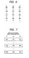
- Fig. 6 shows a selection of a wavelength band.
- switchover is available as 400 ⁇ 405 ⁇ 410 as shown in changing ⁇ 1.
- switchover is as 600 ⁇ 620 ⁇ 640 as shown in changing ⁇ 3, which value is shown on the monitor 34 at its wavelength-information indication area 34s.
- Figs. 3A to 3C shows in detail a display state in the wavelength-information indication area 34s.
- waveform information is to be displayed in the wavelength-information indication area 34s set up on the monitor 34 at its lower right area, as shown in Fig. 3A.
- selected wavelength values are indicated underneath the characters ⁇ 1, ⁇ 2, ⁇ 3, etc., as shown in Fig. 3B.
- wavelength division is taken on the abscissa while sensitivity is on the ordinate so that a selected wavelength band can be visually displayed on a movable graph (correspondingly to Fig. 4).
- the mode change switch 41 d shown in Fig. 2 is to switch between single-color mode and three-color mode.
- pressing the mode change switch 41d provides a switchover into single-color mode so that the microcomputer 35 can set all the wavelength bands ⁇ 1, ⁇ 2, ⁇ 3 at the same value, e.g. 470, 470, 470.
- wavelength band common in value are displayed as shown in Fig. 7. As for such a common wavelength band, a desired value can be selected by the wavelength select switch 41b.
- the mode to make a color display of a spectral image based on fixed three colors and the mode to make a color display of same in a real color of the subject (in a color approximate to the real one).
- the former mode is explained, i.e. the case the fixed-color mode switch 41e in Fig. 2 is being pressed.
- the color-space transforming circuit 29 inputs spectral-image signals ⁇ 1s, ⁇ 2s, ⁇ 3s respectively as signals Rs, Gs, Bs, corresponding to fixed colors (colors, say, at wavelengths of 400 nm, 500 nm, 600 nm), to the second color-conversion circuit 31 regardless of the wavelengths ⁇ 1, ⁇ 2, ⁇ 3.
- the spectral image, displayed on the monitor 34 or to be recorded at the image recorder 45, is given as a color image configured based on the fixed three colors.
- a spectral-image signal ⁇ 1s, ⁇ 2s or ⁇ 3s, representative of a spectral image based on one of the fixed three colors is inputted as an Rs, Gs or Bs signal to the second color-conversion circuit 31.
- the color-space transforming circuit 29 inputs spectral-image signals ⁇ 1s, ⁇ 2s, ⁇ 3s respectively as signals Rs, Gs, Bs, representative of a spectral image in colors at the wavelengths ⁇ 1, ⁇ 2, ⁇ 3, to the second color-conversion circuit 31. Due to this, the spectral image, displayed on the monitor 34 or to be recorded at the image recorder 45, is indicated basically identical in hue to the real one, as to the region of the subject taken an image of by the CCD 15.
- the color-space transforming circuit 29 outputs the spectral-image signals ⁇ 1s, ⁇ 2s, ⁇ 3s, formed by matrix operation according to equation 2, respectively as three-color image signals Rs, Gs, Bs carried with light intensities in colors at wavelengths of 400 nm, 500 nm and 600 nm (in a image display case).
- the color-space transforming circuit 29 outputs spectral-image signals ⁇ 1s, ⁇ 2s, ⁇ 3s respectively formed by the following operations.
- the above nine coefficients "a” - “i” are defined as per the following and stored in a table form based on each combination of wavelengths ⁇ 1, ⁇ 2, ⁇ 3, say, in the memory 36. In operation, those are read out by the microcomputer 35 and inputted to the color-space transforming circuit 29. Provided that the coefficients "a” - “i” are properly defined based on each combination of wavelengths ⁇ 1, ⁇ 2, ⁇ 3, then the spectral image, displayed on the monitor 34 or to be recorded at the image recorder 45, is indicated basically identical in hue to the real one as to the region of the subject taken an image of by the CCD 15.
- the chromaticities at the three wavelengths ⁇ 1, ⁇ 2, ⁇ 3 are assumed respectively as (x 1 , y 1 , z 1 ), (x 2 , y 2 , z 2 ) and (x 3 , y 3 , z 3 ).
- Equation 10 C does not include a negative element.
- coefficients "a” - "i” are determined by forcibly taking as 0 (zero) the negative element resulting from calculation.
- the parameter P1 - P3 coefficients are selected for matrix operation at the color-space transforming circuit 29. Due to this, the color-space transforming circuit 29 outputs the RGB signal, which the first color-conversion circuit 28 outputted, without change.
- the RGB signal is converted into a Y/C signal at the second color-conversion circuit 31.
- the Y/C signal is inputted through the signal processing circuit 32 and D/A converter 33 onto the monitor 34.
- the monitor 34 displays thereon an ordinary color image (moving or still image) of the subject.
- the output of the D/A converter 33 is inputted to the image recorder 45 besides to the monitor 34.
- the image recorder 45 outputs an ordinary color image of or a spectral-image hard copy of a scene as designated by the instruction.
- the invention is not limited to such embodiments and examples but various modifications are also possible.
- the values of the radii of curvature, surface intervals and refractive indexes of the respective lens components are not limited to the values that are shown in the above-mentioned numerical examples, but other values can also be used.
- the both surfaces of the first to fourth lenses are all formed as aspherical surfaces; however, the invention is not limited to this.
Landscapes
- Health & Medical Sciences (AREA)
- Life Sciences & Earth Sciences (AREA)
- Surgery (AREA)
- Physics & Mathematics (AREA)
- General Health & Medical Sciences (AREA)
- Molecular Biology (AREA)
- Pathology (AREA)
- Veterinary Medicine (AREA)
- Public Health (AREA)
- Engineering & Computer Science (AREA)
- Biomedical Technology (AREA)
- Heart & Thoracic Surgery (AREA)
- Medical Informatics (AREA)
- Biophysics (AREA)
- Animal Behavior & Ethology (AREA)
- Optics & Photonics (AREA)
- Nuclear Medicine, Radiotherapy & Molecular Imaging (AREA)
- Radiology & Medical Imaging (AREA)
- Spectroscopy & Molecular Physics (AREA)
- Endoscopes (AREA)
- Closed-Circuit Television Systems (AREA)
- Instruments For Viewing The Inside Of Hollow Bodies (AREA)
Applications Claiming Priority (1)
| Application Number | Priority Date | Filing Date | Title |
|---|---|---|---|
| JP2006267104A JP4931199B2 (ja) | 2006-09-29 | 2006-09-29 | 電子内視鏡装置 |
Publications (2)
| Publication Number | Publication Date |
|---|---|
| EP1905347A2 true EP1905347A2 (fr) | 2008-04-02 |
| EP1905347A3 EP1905347A3 (fr) | 2008-07-02 |
Family
ID=38951754
Family Applications (1)
| Application Number | Title | Priority Date | Filing Date |
|---|---|---|---|
| EP07019051A Withdrawn EP1905347A3 (fr) | 2006-09-29 | 2007-09-27 | Appareil d'endoscope électronique |
Country Status (5)
| Country | Link |
|---|---|
| US (1) | US8125514B2 (fr) |
| EP (1) | EP1905347A3 (fr) |
| JP (1) | JP4931199B2 (fr) |
| KR (1) | KR20080030492A (fr) |
| CN (1) | CN101152073B (fr) |
Cited By (3)
| Publication number | Priority date | Publication date | Assignee | Title |
|---|---|---|---|---|
| EP2189099A1 (fr) * | 2008-11-21 | 2010-05-26 | Fujifilm Corporation | Appareil d'endoscope et son procédé de commande |
| EP2258251A1 (fr) * | 2009-06-05 | 2010-12-08 | Fujifilm Corporation | Procédé pour obtenir une image et appareil endoscopique |
| EP2453376A3 (fr) * | 2010-11-15 | 2012-09-26 | Fujifilm Corporation | Appareil de reproduction/enregistrement d'images médicales, procédé de reproduction/enregistrement d'images médicales et programme |
Families Citing this family (42)
| Publication number | Priority date | Publication date | Assignee | Title |
|---|---|---|---|---|
| JP4931199B2 (ja) * | 2006-09-29 | 2012-05-16 | 富士フイルム株式会社 | 電子内視鏡装置 |
| KR100986061B1 (ko) | 2008-04-01 | 2010-10-07 | 현대자동차주식회사 | 배기 매니폴드와 실린더 헤드가 일체형으로 형성된 엔진 |
| JP5389380B2 (ja) * | 2008-05-28 | 2014-01-15 | オリンパス株式会社 | 信号処理システム及び信号処理プログラム |
| JP5294723B2 (ja) * | 2008-06-26 | 2013-09-18 | 富士フイルム株式会社 | 画像取得装置 |
| JP4717103B2 (ja) * | 2008-07-18 | 2011-07-06 | オリンパス株式会社 | 信号処理システム及び信号処理プログラム |
| US9402533B2 (en) | 2011-03-07 | 2016-08-02 | Endochoice Innovation Center Ltd. | Endoscope circuit board assembly |
| US11864734B2 (en) | 2009-06-18 | 2024-01-09 | Endochoice, Inc. | Multi-camera endoscope |
| US9901244B2 (en) | 2009-06-18 | 2018-02-27 | Endochoice, Inc. | Circuit board assembly of a multiple viewing elements endoscope |
| US11278190B2 (en) | 2009-06-18 | 2022-03-22 | Endochoice, Inc. | Multi-viewing element endoscope |
| US9706903B2 (en) | 2009-06-18 | 2017-07-18 | Endochoice, Inc. | Multiple viewing elements endoscope system with modular imaging units |
| US9642513B2 (en) | 2009-06-18 | 2017-05-09 | Endochoice Inc. | Compact multi-viewing element endoscope system |
| EP2442706B1 (fr) | 2009-06-18 | 2014-11-12 | EndoChoice Innovation Center Ltd. | Endoscope à caméras multiples |
| US9492063B2 (en) | 2009-06-18 | 2016-11-15 | Endochoice Innovation Center Ltd. | Multi-viewing element endoscope |
| US9872609B2 (en) | 2009-06-18 | 2018-01-23 | Endochoice Innovation Center Ltd. | Multi-camera endoscope |
| WO2012077116A1 (fr) | 2010-12-09 | 2012-06-14 | Peermedical Ltd. | Carte de circuit électronique flexible pour endoscope à caméras multiples |
| US9101287B2 (en) | 2011-03-07 | 2015-08-11 | Endochoice Innovation Center Ltd. | Multi camera endoscope assembly having multiple working channels |
| US12137873B2 (en) | 2009-06-18 | 2024-11-12 | Endochoice, Inc. | Compact multi-viewing element endoscope system |
| US10165929B2 (en) | 2009-06-18 | 2019-01-01 | Endochoice, Inc. | Compact multi-viewing element endoscope system |
| US11547275B2 (en) | 2009-06-18 | 2023-01-10 | Endochoice, Inc. | Compact multi-viewing element endoscope system |
| US9713417B2 (en) | 2009-06-18 | 2017-07-25 | Endochoice, Inc. | Image capture assembly for use in a multi-viewing elements endoscope |
| US8926502B2 (en) | 2011-03-07 | 2015-01-06 | Endochoice, Inc. | Multi camera endoscope having a side service channel |
| US9101268B2 (en) | 2009-06-18 | 2015-08-11 | Endochoice Innovation Center Ltd. | Multi-camera endoscope |
| US12220105B2 (en) | 2010-06-16 | 2025-02-11 | Endochoice, Inc. | Circuit board assembly of a multiple viewing elements endoscope |
| US9560953B2 (en) | 2010-09-20 | 2017-02-07 | Endochoice, Inc. | Operational interface in a multi-viewing element endoscope |
| EP4233680B1 (fr) | 2010-09-20 | 2025-06-18 | EndoChoice, Inc. | Section distal d'endoscope comprenant un composant unique de canalisation de fluides |
| EP2635932B1 (fr) | 2010-10-28 | 2019-06-05 | EndoChoice Innovation Center Ltd. | Systèmes optiques pour endoscopes à capteurs multiples |
| US12204087B2 (en) | 2010-10-28 | 2025-01-21 | Endochoice, Inc. | Optical systems for multi-sensor endoscopes |
| JP5694882B2 (ja) * | 2010-11-30 | 2015-04-01 | 富士フイルム株式会社 | 放射線検出素子及び放射線画像撮影装置 |
| EP3420886B8 (fr) | 2010-12-09 | 2020-07-15 | EndoChoice, Inc. | Endoscope multicaméra à carte de circuit électronique souple |
| US11889986B2 (en) | 2010-12-09 | 2024-02-06 | Endochoice, Inc. | Flexible electronic circuit board for a multi-camera endoscope |
| CN103491854B (zh) | 2011-02-07 | 2016-08-24 | 恩多卓斯创新中心有限公司 | 用于多摄影机内窥镜的多元件罩 |
| KR20120097828A (ko) | 2011-02-25 | 2012-09-05 | 삼성전자주식회사 | 협대역 영상을 제공할 수 있는 내시경 장치 및 상기 내시경 장치의 영상 처리 방법 |
| JP5789232B2 (ja) * | 2011-10-12 | 2015-10-07 | 富士フイルム株式会社 | 内視鏡システム及びその作動方法 |
| CA2798729A1 (fr) | 2011-12-13 | 2013-06-13 | Peermedical Ltd. | Connecteur rotatif pour un endoscope |
| CA2798716A1 (fr) | 2011-12-13 | 2013-06-13 | Endochoice Innovation Center Ltd. | Endoscope a pointe amovible |
| US9560954B2 (en) | 2012-07-24 | 2017-02-07 | Endochoice, Inc. | Connector for use with endoscope |
| US9986899B2 (en) | 2013-03-28 | 2018-06-05 | Endochoice, Inc. | Manifold for a multiple viewing elements endoscope |
| US9993142B2 (en) | 2013-03-28 | 2018-06-12 | Endochoice, Inc. | Fluid distribution device for a multiple viewing elements endoscope |
| US10499794B2 (en) | 2013-05-09 | 2019-12-10 | Endochoice, Inc. | Operational interface in a multi-viewing element endoscope |
| US10400967B2 (en) * | 2016-06-13 | 2019-09-03 | Novartis Ag | Ophthalmic illumination system with controlled chromaticity |
| US20180279862A1 (en) * | 2016-10-10 | 2018-10-04 | Jack Wade | Systems and methods for closed-loop medical imaging |
| JP6960773B2 (ja) * | 2017-05-26 | 2021-11-05 | 池上通信機株式会社 | 撮像画像処理システム |
Citations (2)
| Publication number | Priority date | Publication date | Assignee | Title |
|---|---|---|---|---|
| JPH0796005B2 (ja) | 1987-10-27 | 1995-10-18 | オリンパス光学工業株式会社 | 内視鏡装置 |
| JP2003093336A (ja) | 2001-09-26 | 2003-04-02 | Toshiba Corp | 電子内視鏡装置 |
Family Cites Families (13)
| Publication number | Priority date | Publication date | Assignee | Title |
|---|---|---|---|---|
| JP3217343B2 (ja) * | 1989-03-23 | 2001-10-09 | オリンパス光学工業株式会社 | 画像処理装置 |
| AU2001237338A1 (en) * | 2000-01-25 | 2001-08-07 | 4D-Vision Gmbh | Method and system for the three-dimensional representation |
| JP2001339742A (ja) * | 2000-03-21 | 2001-12-07 | Olympus Optical Co Ltd | 立体映像プロジェクション装置、及びその補正量演算装置 |
| US7892169B2 (en) * | 2000-07-21 | 2011-02-22 | Olympus Corporation | Endoscope apparatus |
| JP4388318B2 (ja) | 2003-06-27 | 2009-12-24 | オリンパス株式会社 | 画像処理装置 |
| EP1698272B1 (fr) * | 2005-03-04 | 2012-12-05 | FUJIFILM Corporation | Endoscope et dispositif de traitement d'images |
| JP4579721B2 (ja) * | 2005-03-04 | 2010-11-10 | 富士フイルム株式会社 | 内視鏡装置 |
| JP4732769B2 (ja) * | 2005-03-04 | 2011-07-27 | 富士フイルム株式会社 | 内視鏡装置 |
| JP4647346B2 (ja) * | 2005-03-04 | 2011-03-09 | 富士フイルム株式会社 | 内視鏡装置 |
| JP4647347B2 (ja) | 2005-03-04 | 2011-03-09 | 富士フイルム株式会社 | 内視鏡装置 |
| BRPI0609099A2 (pt) | 2005-05-12 | 2010-02-17 | Olympus Medical Systems Corp | aparelho de observação biológica |
| US7525704B2 (en) * | 2005-12-20 | 2009-04-28 | Xerox Corporation | System for providing depth discrimination of source images encoded in a rendered composite image |
| JP4931199B2 (ja) * | 2006-09-29 | 2012-05-16 | 富士フイルム株式会社 | 電子内視鏡装置 |
-
2006
- 2006-09-29 JP JP2006267104A patent/JP4931199B2/ja not_active Expired - Fee Related
-
2007
- 2007-09-21 KR KR1020070096950A patent/KR20080030492A/ko not_active Ceased
- 2007-09-27 EP EP07019051A patent/EP1905347A3/fr not_active Withdrawn
- 2007-09-27 US US11/862,247 patent/US8125514B2/en not_active Expired - Fee Related
- 2007-09-29 CN CN2007101624093A patent/CN101152073B/zh not_active Expired - Fee Related
Patent Citations (2)
| Publication number | Priority date | Publication date | Assignee | Title |
|---|---|---|---|---|
| JPH0796005B2 (ja) | 1987-10-27 | 1995-10-18 | オリンパス光学工業株式会社 | 内視鏡装置 |
| JP2003093336A (ja) | 2001-09-26 | 2003-04-02 | Toshiba Corp | 電子内視鏡装置 |
Cited By (5)
| Publication number | Priority date | Publication date | Assignee | Title |
|---|---|---|---|---|
| EP2189099A1 (fr) * | 2008-11-21 | 2010-05-26 | Fujifilm Corporation | Appareil d'endoscope et son procédé de commande |
| US8439823B2 (en) | 2008-11-21 | 2013-05-14 | Fujifilm Corporation | Endoscope apparatus and its control method |
| EP2258251A1 (fr) * | 2009-06-05 | 2010-12-08 | Fujifilm Corporation | Procédé pour obtenir une image et appareil endoscopique |
| EP2453376A3 (fr) * | 2010-11-15 | 2012-09-26 | Fujifilm Corporation | Appareil de reproduction/enregistrement d'images médicales, procédé de reproduction/enregistrement d'images médicales et programme |
| US9589103B2 (en) | 2010-11-15 | 2017-03-07 | Fujifilm Corporation | Medical image recording/reproducing apparatus, medical image recording/reproducing method and computer readable medium |
Also Published As
| Publication number | Publication date |
|---|---|
| US20080079803A1 (en) | 2008-04-03 |
| EP1905347A3 (fr) | 2008-07-02 |
| KR20080030492A (ko) | 2008-04-04 |
| US8125514B2 (en) | 2012-02-28 |
| JP2008086347A (ja) | 2008-04-17 |
| CN101152073B (zh) | 2010-09-08 |
| CN101152073A (zh) | 2008-04-02 |
| JP4931199B2 (ja) | 2012-05-16 |
Similar Documents
| Publication | Publication Date | Title |
|---|---|---|
| US8125514B2 (en) | Electronic endoscope apparatus | |
| EP1698272B1 (fr) | Endoscope et dispositif de traitement d'images | |
| JP4732769B2 (ja) | 内視鏡装置 | |
| EP1813185A1 (fr) | Appareil d'endoscope électronique | |
| EP2821003A1 (fr) | Système d'endoscope et son procédé de fonctionnement | |
| JP4637620B2 (ja) | 内視鏡システム装置 | |
| JP4579721B2 (ja) | 内視鏡装置 | |
| EP1813186B1 (fr) | Système endoscopique | |
| EP1774897B1 (fr) | Appareil d'endoscopie | |
| JP5039621B2 (ja) | 電子内視鏡装置 | |
| EP2105086B1 (fr) | Appareil d'endoscope électronique | |
| JP4813145B2 (ja) | 内視鏡装置 | |
| JP2010115341A (ja) | 電子内視鏡装置 | |
| JP2010051602A (ja) | 電子内視鏡装置および方法並びにプログラム |
Legal Events
| Date | Code | Title | Description |
|---|---|---|---|
| PUAI | Public reference made under article 153(3) epc to a published international application that has entered the european phase |
Free format text: ORIGINAL CODE: 0009012 |
|
| 17P | Request for examination filed |
Effective date: 20070927 |
|
| AK | Designated contracting states |
Kind code of ref document: A2 Designated state(s): AT BE BG CH CY CZ DE DK EE ES FI FR GB GR HU IE IS IT LI LT LU LV MC MT NL PL PT RO SE SI SK TR |
|
| AX | Request for extension of the european patent |
Extension state: AL BA HR MK YU |
|
| PUAL | Search report despatched |
Free format text: ORIGINAL CODE: 0009013 |
|
| AK | Designated contracting states |
Kind code of ref document: A3 Designated state(s): AT BE BG CH CY CZ DE DK EE ES FI FR GB GR HU IE IS IT LI LT LU LV MC MT NL PL PT RO SE SI SK TR |
|
| AX | Request for extension of the european patent |
Extension state: AL BA HR MK RS |
|
| AKX | Designation fees paid |
Designated state(s): AT BE BG CH CY CZ DE DK EE ES FI FR GB GR HU IE IS IT LI LT LU LV MC MT NL PL PT RO SE SI SK TR |
|
| RAP1 | Party data changed (applicant data changed or rights of an application transferred) |
Owner name: FUJIFILM CORPORATION |
|
| 17Q | First examination report despatched |
Effective date: 20131122 |
|
| STAA | Information on the status of an ep patent application or granted ep patent |
Free format text: STATUS: THE APPLICATION IS DEEMED TO BE WITHDRAWN |
|
| 18D | Application deemed to be withdrawn |
Effective date: 20160401 |