EP1905366B1 - Système de stabilisation cervicale dynamique - Google Patents
Système de stabilisation cervicale dynamique Download PDFInfo
- Publication number
- EP1905366B1 EP1905366B1 EP07117269A EP07117269A EP1905366B1 EP 1905366 B1 EP1905366 B1 EP 1905366B1 EP 07117269 A EP07117269 A EP 07117269A EP 07117269 A EP07117269 A EP 07117269A EP 1905366 B1 EP1905366 B1 EP 1905366B1
- Authority
- EP
- European Patent Office
- Prior art keywords
- plate assembly
- flexible core
- flexible
- vertebral
- core
- Prior art date
- Legal status (The legal status is an assumption and is not a legal conclusion. Google has not performed a legal analysis and makes no representation as to the accuracy of the status listed.)
- Ceased
Links
- 230000006641 stabilisation Effects 0.000 title claims abstract description 34
- 238000011105 stabilization Methods 0.000 title claims abstract description 34
- 210000000988 bone and bone Anatomy 0.000 claims abstract description 37
- 239000000463 material Substances 0.000 claims description 12
- 230000006835 compression Effects 0.000 claims description 6
- 238000007906 compression Methods 0.000 claims description 6
- RTAQQCXQSZGOHL-UHFFFAOYSA-N Titanium Chemical compound [Ti] RTAQQCXQSZGOHL-UHFFFAOYSA-N 0.000 claims description 4
- 239000010936 titanium Substances 0.000 claims description 4
- 229910052719 titanium Inorganic materials 0.000 claims description 4
- 206010016654 Fibrosis Diseases 0.000 claims description 3
- 230000003278 mimic effect Effects 0.000 claims description 3
- 239000011162 core material Substances 0.000 description 52
- 230000004927 fusion Effects 0.000 description 9
- 239000000243 solution Substances 0.000 description 8
- 230000008929 regeneration Effects 0.000 description 7
- 238000011069 regeneration method Methods 0.000 description 7
- 230000009469 supplementation Effects 0.000 description 6
- 230000035876 healing Effects 0.000 description 5
- 239000007943 implant Substances 0.000 description 5
- 239000012634 fragment Substances 0.000 description 4
- 230000001537 neural effect Effects 0.000 description 4
- 239000013589 supplement Substances 0.000 description 4
- 210000004705 lumbosacral region Anatomy 0.000 description 3
- 208000031481 Pathologic Constriction Diseases 0.000 description 2
- 208000027418 Wounds and injury Diseases 0.000 description 2
- 230000006378 damage Effects 0.000 description 2
- 230000003412 degenerative effect Effects 0.000 description 2
- 238000006073 displacement reaction Methods 0.000 description 2
- 238000002347 injection Methods 0.000 description 2
- 239000007924 injection Substances 0.000 description 2
- 208000014674 injury Diseases 0.000 description 2
- 229910052751 metal Inorganic materials 0.000 description 2
- 239000002184 metal Substances 0.000 description 2
- 230000036262 stenosis Effects 0.000 description 2
- 208000037804 stenosis Diseases 0.000 description 2
- 230000002159 abnormal effect Effects 0.000 description 1
- 239000012620 biological material Substances 0.000 description 1
- 210000000845 cartilage Anatomy 0.000 description 1
- 239000013013 elastic material Substances 0.000 description 1
- 238000001125 extrusion Methods 0.000 description 1
- 230000004761 fibrosis Effects 0.000 description 1
- 150000002739 metals Chemical class 0.000 description 1
- 230000007935 neutral effect Effects 0.000 description 1
- 230000001172 regenerating effect Effects 0.000 description 1
- 210000000278 spinal cord Anatomy 0.000 description 1
- 210000001032 spinal nerve Anatomy 0.000 description 1
- 210000000130 stem cell Anatomy 0.000 description 1
- 230000017423 tissue regeneration Effects 0.000 description 1
Images

Classifications
-
- A—HUMAN NECESSITIES
- A61—MEDICAL OR VETERINARY SCIENCE; HYGIENE
- A61B—DIAGNOSIS; SURGERY; IDENTIFICATION
- A61B17/00—Surgical instruments, devices or methods
- A61B17/56—Surgical instruments or methods for treatment of bones or joints; Devices specially adapted therefor
- A61B17/58—Surgical instruments or methods for treatment of bones or joints; Devices specially adapted therefor for osteosynthesis, e.g. bone plates, screws or setting implements
- A61B17/68—Internal fixation devices, including fasteners and spinal fixators, even if a part thereof projects from the skin
- A61B17/70—Spinal positioners or stabilisers, e.g. stabilisers comprising fluid filler in an implant
- A61B17/7059—Cortical plates
-
- A—HUMAN NECESSITIES
- A61—MEDICAL OR VETERINARY SCIENCE; HYGIENE
- A61B—DIAGNOSIS; SURGERY; IDENTIFICATION
- A61B17/00—Surgical instruments, devices or methods
- A61B17/56—Surgical instruments or methods for treatment of bones or joints; Devices specially adapted therefor
- A61B17/58—Surgical instruments or methods for treatment of bones or joints; Devices specially adapted therefor for osteosynthesis, e.g. bone plates, screws or setting implements
- A61B17/68—Internal fixation devices, including fasteners and spinal fixators, even if a part thereof projects from the skin
- A61B17/80—Cortical plates, i.e. bone plates; Instruments for holding or positioning cortical plates, or for compressing bones attached to cortical plates
- A61B17/8033—Cortical plates, i.e. bone plates; Instruments for holding or positioning cortical plates, or for compressing bones attached to cortical plates having indirect contact with screw heads, or having contact with screw heads maintained with the aid of additional components, e.g. nuts, wedges or head covers
-
- A—HUMAN NECESSITIES
- A61—MEDICAL OR VETERINARY SCIENCE; HYGIENE
- A61B—DIAGNOSIS; SURGERY; IDENTIFICATION
- A61B17/00—Surgical instruments, devices or methods
- A61B17/56—Surgical instruments or methods for treatment of bones or joints; Devices specially adapted therefor
- A61B17/58—Surgical instruments or methods for treatment of bones or joints; Devices specially adapted therefor for osteosynthesis, e.g. bone plates, screws or setting implements
- A61B17/68—Internal fixation devices, including fasteners and spinal fixators, even if a part thereof projects from the skin
- A61B17/80—Cortical plates, i.e. bone plates; Instruments for holding or positioning cortical plates, or for compressing bones attached to cortical plates
- A61B17/8085—Cortical plates, i.e. bone plates; Instruments for holding or positioning cortical plates, or for compressing bones attached to cortical plates with pliable or malleable elements or having a mesh-like structure, e.g. small strips
-
- A—HUMAN NECESSITIES
- A61—MEDICAL OR VETERINARY SCIENCE; HYGIENE
- A61B—DIAGNOSIS; SURGERY; IDENTIFICATION
- A61B17/00—Surgical instruments, devices or methods
- A61B17/56—Surgical instruments or methods for treatment of bones or joints; Devices specially adapted therefor
- A61B17/58—Surgical instruments or methods for treatment of bones or joints; Devices specially adapted therefor for osteosynthesis, e.g. bone plates, screws or setting implements
- A61B17/68—Internal fixation devices, including fasteners and spinal fixators, even if a part thereof projects from the skin
- A61B17/80—Cortical plates, i.e. bone plates; Instruments for holding or positioning cortical plates, or for compressing bones attached to cortical plates
- A61B17/8004—Cortical plates, i.e. bone plates; Instruments for holding or positioning cortical plates, or for compressing bones attached to cortical plates with means for distracting or compressing the bone or bones
Definitions
- the present invention relates in general to a vertebral stabilization implant.
- the present invention relates to a vertebral column dynamic stabilization device that supplements vertebral stabilization via the anterior column and/or the middle column lip and that can also facilitate disc regeneration.
- Each vertebra has a cyfindrical-shaped vertebral body in the anterior portion of the spine with an arch of bone to the posterior that covers the neural structures. Between each vertebral body is an intervertebral disk, a cartilaginous cushion to help absorb impact and dampen compressive forces on the spine. To the posterior, the laminar arch covers the neural structures of the spinal cord and nerves for protection. At the junction of the arch and anterior vertebral body are articulations to allow movement of the spine.
- a posterior system for the lumbar spine with a pedicle screw base system and a flexible rod attachment is known as the Zimmer Spine Dynesis System.
- the Zimmer system though is a posterior system and has no application in the cervical spine or for anterior applications.
- a posterior system for the lumbar spine with a pedicle screw base system and a flexible rod attachment is known as the Zimmer Spine Dynesis System
- the Zimmer system though is a posterior system and has no application in the cervical spine or for anterior applications.
- a device as described in further detail below provides a flexible plate that allows partial sharing of the weight of the vertebral bodies to promote bone healing or support at partial discectomy.
- a bone will not heal if it is stress-shielded from all weight bearing If a partial discectomy is not supported, then it will collapse Therefore, one aspect of the subject application provides a device that is strong enough to resist collapsing forces or abnormal angulation during the healing of the bone and/or disc.
- the present invention provides a dynamic stabilization device which includes a weight bearing plate and a flexible core.
- a dynamic stabilization device which includes a weight bearing plate and a flexible core.
- an anterior column dynamic stabilization device is provided which allows supplementation of stabilization via the anterior column
- the flexible core is located in the midportion of the plate and is mobile in all planes of motion, allowing six planes of motion to mimic a natural motion of the neck.
- the plate may include attachment features such as caps, screws, and a lip to provide additional stability
- anterior column stabilization and/or stabilization of the middle lip of the vertebral body column is provided. Due to the placement and structure of a stabilization plate, disc regeneration is also facilitated.
- the plate or device stabilizes the vertebrae, such as in a patient's neck, in an "open" position, preventing a subsequent collapse after partial removal of disc material. With the vertebrae stabilized in the open or height-maintained position, the disc material is allowed to fibrose in naturally over a healing period (e.g., six-to-eight-week period) to yield regeneration and fibrosis of the disc in the open space between the vertebrae. Due to the structure of the stabilization plate, the motion segment is preserved After the disc has fibrosed in or regenerated, the plate can also provide some additional stability to the segment in the absence of fusion.
- a healing period e.g., six-to-eight-week period
- the present invention is distinctly different from an artificial disc, which involves replacement of a disc with a mechanical device when a total discectomy is performed. Rather, the subject invention can supplement the patient's natural disc and adds stability to the anterior and/or middle column lip to facilitate disc regeneration. Furthermore, the subject invention may be used to supplement fusion of a disc with partial weight sharing of the bone.
- the subject invention is also different from any type of nuclear replacement, which is a biologic or gel replacement of the disc nucleus. That is, the present invention can allow the disc to heal naturally as opposed to requiring a nuclear replacement.
- a vertebral stabilization plate assembly that facilitates anterior columnar stabilization
- the plate assembly comprises a flexible core located in a mid-portion section of the plate assembly; at least a first and a second attachment portion positioned above and below the flexible core, wherein the first and the second attachment portions comprise a plurality of fastener holes through which a plurality of fasteners are inserted to attach the plate assembly to at least two vertebral bone structures, and at least one flexible cable that extends through at least a first portion of the flexible core to maintain a position of the flexible core within the plate assembly, wherein the plate assembly is weight-bearing and when attached to the at least two vertebral bone structures, extends across a disc space located between the at least two vertebral bone structures
- a vertebral stabilization plate assembly that facilitates anterior columnar stabilization.
- the plate assembly includes a flexible core located in a mid-portion section of the plate assembly; at least a first and a second attachment portions positioned above and below and at least partially overlapping the flexible core, wherein the first and the second attachment portions comprise a plurality of screw holes through which a plurality of screws are inserted to attach the plate assembly to at least two vertebral bone structures; and a plurality of caps having a general U-shaped configuration that each fit around top and bottom end portions of the flexible core, wherein the plate assembly is weight-bearing and when attached to the at least two vertebral bone structures, the plate assembly has a compression capability that holds a disc space located between the at least two vertebral bone structures open while still allowing compression, rotation, flexion, and extension that mimics natural movement of the at least two vertebral bone structures, thereby preventing collapse of the disc space.
- FIG. 1 is a front or top view of a first embodiment of the present invention
- FIG. 2 is a side view of the first embodiment of the present invention
- FIG. 3 is a side view of a second embodiment of the present invention.
- FIG. 4 is an expanded front or top view of the second embodiment of the present invention.
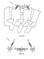
- FIG. 5 is an expanded side view of an embodiment of the present invention that contains a lip portion on the flexible core of the plate assembly as it may appear in relation to two vertebrae,
- FIG. 6 is an expanded side view of another embodiment of the present invention that contains a lip portion on the flexible core of the plate assembly and
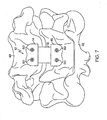
- FIG 7 is a front or top view of an embodiment of the present invention as it may appear in relation to two Vertebrae.
- a plate of the present invention can be used to facilitate disc regeneration and vertebral stabilization as well as to provide supplementation to a bone graft
- the subject plate can also supplement stabilization for fusion and/or can allow partial weight bearing or weight loading in a dynamic way to a bone graft.
- the plate can provide partial protection from extrusion or over-collapse, thus allowing the bone to regenerate or heal at a faster rate via Wolff's law
- Conventional cervical plates employ mechanical weight bearing and require the use of a titanium plate but lack a plate having a flexible core that permits the full range of motion in six planes.
- the present invention can have non-fusion applications, such as when a standard discectomy is performed in a conventional manner, but where anterior column secondary stability is desired to prevent any over-collapse of the space. Additionally, the present invention can be applied to tissue regeneration technology to allow stabilization of a disc space in an open, non-collapsed position, thereby allowing regeneration of the disc..
- the present invention can involve a stabilization plate that includes a flexible core portion which permits not only a full range of motion but also permits the plate to bear weight Having a plate assembly helps to promote natural healing of a disc after partial surgical excision of a disc or injury to a disc Unlike conventional spinal implants or devices, no other implant is needed to assist in the weight-bearing forces such as during the healing period.
- the stabilization plate as described herein has a compression capability to hold a surgical space open at approximately 6-7mm in height while still allowing compression, rotation, flexion, and extension in approximately the 5-7 degree range and allowing approximately 2-3 mm of motion in any plane.
- the stiffness of the stabilization plate can be determined by the density selection of the flexible core material of the plate
- the present invention may allow for potential applications in stem cell technology, cartilage regenerative injection technology, or subsequent stabilization for biomaterials for nuclear implants.
- Each of these devices and/or injections requires stabilization of an injured segment in a neutral position and can apply the flexible core of the present invention
- the flexible core will not necessarily create fusion or regeneration, unless bone or bone generation materials are also provided.
- a plate assembly 10 includes a flexible core 12 with attachment portions 4, 6 above and below (or adjacent to either side of) the flexible core 12
- the attachment portions 4, 6 are comprised of a metal.
- the attachment portions 4, 6 can be made of titanium or other suitable metals Alternatively, the attachment portions 4, 6 may be comprised of a hard material that is non-metallic.
- a plurality of screws can be placed in the vertebral body in a plurality of screw-holes 18 (or other fastener-holes 18) that correspond to each attachment portion 4, 6 located above and below the flexible core 12.
- attachment portions 4, 6 can also be described as being positioned at each opposite end of the flexible core and/or in end portions of the plate assembly
- the attachment portions 4, 6 have a width that can be larger than the flexible core 12
- the attachment portions 4, 6 contain the screw-holes 18 to allow attachment of a plurality of screws to the plate assembly 10 and to a bone structure without the occurrence of any pull-through.
- a cover lock 22 can be provided to ensure that the screws do not back-out of the screw-holes 18.
- the flexible core 12 comprises a dense but mobile plastic It is to be appreciated that other flexible and/or elastic materials may be used.
- the flexible core may include a soft gel material.
- the flexible core 12 may be multi-component and/or multi-material.
- the flexible core 12 with the flexible/elastic properties allows the six planes of motion to mimic a natural motion of the vertrbrea
- the flexible core 12 may be maintained in position with at least one flexible cable 20, which extends through the flexible core 12. In the shown example, there are two flexible cables. However, a different number of cables (e g , none, one or more than two) may be used.
- the flexible cables 20 can be made of titanium or other strong but flexible materials The flexible cables 20 assist in providing resistance to forces that rotate, flex, and extend the flexible core 12.
- the flexible core 12 may also be made of a biologically compatible material and may act as a flexible central bumper.
- FIG. 2 a side view of the first embodiment is shown
- One flexible cable 20 can be seen in relatively the middle portion of the flexible core 12.
- the flexible cable 20 may be in locations other than the middle portion of the flexible core 12.
- the flexible core 12 extends between each attachment portion 4, 6 and extends across multiple vertebrae.
- caps 14, 16 fit around the two end portions (or top and bottom portions depending on the orientation of the flexible core 12) of the flexible core 12 and have a generally U-shaped configuration
- the caps 14, 16 in this embodiment can have a width that is larger than the width of the flexible core 12.
- the flexible core 12 extends across multiple vertebrae Furthermore, the flexible core 12 can extend almost the entire length of the plate assembly 10 due to the shape and orientation of the caps 14, 16.
- FIG. 4 shows an embodiment that demonstrates one way to assemble the plate assembly 10.
- the caps 14, 16 are shown oriented in the manner in which they will be assembled onto the flexible core 12
- the screw-holes 18 on each cap 14, 16 correspond to screw-holes 18 located on the flexible core
- An initial step in assembling this embodiment is to ensure that each cap (14, 16) is oriented onto the flexible core 12 to permit the entry of screws. This orientation will only be performed once the plate assembly 10 is in the proper location for purposes of supplementation of a bone graft. Once screws are inserted into each screw-hole 18, the plate assembly 10 is thus assembled.
- the flexible core 12 contains a lip 30 as illustrated when implanted into two vertebral bone structures 40, 42
- the lip 30 extends from the flexible core 12 into an area located between two rigid vertebral bone structures 40, 42.
- the lip 30 contains edges 32 that mate with the corresponding edges of the vertebral bone structures 40, 42.
- the lip 30 can extend slightly from the anterior column into the middle column of a vertebral body, under the lips of the vertebral body However, the lip 30 does not extend well into the disc space or replace any disc in any way The lip 30 extends slightly to engage the anterior column lips for further stability of the flexible core 12
- screws 50 can be used to connect the plate assembly 10 to the vertebral bone structures 40, 42. It is to be appreciated that in other embodiments, other fastener devices may be used in place of the screws 50
- FIG. 6 an assembly is shown that contains a flexible core 12 with a lip 30.
- the lip contains edges 32 that mate with the corresponding edges of vertebrae structures.
- the edges 32 can be comprised of an angular edge as in FIG. 6 or an edge that is formed from a substantially right angle, as in FIG. 5
- the embodiment in FIG. 6 also contains caps 14, 16 that fit around the two end portions of the flexible core 12; and the caps 14, 16 have a generally U-shaped configuration.
- the flexible core 12 extends across multiple vertebrae (e.g., at least two vertebrae) In addition, the flexible core 12 extends almost the entire length of the plate assembly 10 due to the shape and orientation of the caps 14, 16 Though screws 50 can be used to connect the plate assembly 10 to the vertebrae structure as shown, it should be understood that other fastener devices may be used in place of the screws 50
- FIG 7 depicts a top view of an example stabilization plate assembly 10 attached to at least two vertebral bone structures 40, 42 via screws 50
- the present invention may be used in a cervical region or in application to the lower levels in the lumbar spine
- the present invention can be used in the L4-5 or L5-S1 vertebrae levels for supplementation of a disc injury, however, the profile, or height, of the flexible core and the plate should be kept to a minimum amount.
- the plate assembly can be employed with respect to other parts of the spine as well
- cover locks can be added to any embodiment of the design to prevent the backout of any screw or fastener device and to prevent the displacement of the flexible core
Landscapes
- Health & Medical Sciences (AREA)
- Orthopedic Medicine & Surgery (AREA)
- Life Sciences & Earth Sciences (AREA)
- Surgery (AREA)
- Neurology (AREA)
- Molecular Biology (AREA)
- General Health & Medical Sciences (AREA)
- Biomedical Technology (AREA)
- Heart & Thoracic Surgery (AREA)
- Medical Informatics (AREA)
- Nuclear Medicine, Radiotherapy & Molecular Imaging (AREA)
- Animal Behavior & Ethology (AREA)
- Engineering & Computer Science (AREA)
- Public Health (AREA)
- Veterinary Medicine (AREA)
- Prostheses (AREA)
- Surgical Instruments (AREA)
- Paper (AREA)
- Amplifiers (AREA)
- Stereophonic System (AREA)
Claims (20)
- Ensemble de plaque de stabilisation vertébrale (10) qui facilite la stabilisation colonnaire antérieure, l'ensemble de plaque (10) comprenant :un noyau flexible (12) positionné dans une section de partie centrale de l'ensemble de plaque (10) ;au moins une première (4) et une seconde (6) partie de fixation positionnées au-dessus et au-dessous du noyau flexible (12), dans lequel la première (4) et la seconde (6) partie de fixation comprennent une pluralité de trous de fixation (18) à travers lesquels plusieurs fixations (50) sont insérées afin de fixer l'ensemble de plaque (10) sur au moins deux structures osseuses vertébrales ; etau moins un câble flexible (20) qui s'étend à travers au moins une première partie du noyau flexible (12) afin de maintenir une position du noyau flexible (12) à l'intérieur de l'ensemble de plaque (10), dans lequel l'ensemble de plaque (10) est mis en charge et lorsqu'il est fixé aux au moins deux structures osseuses vertébrales, s'étend sur un espace de disque situé entre les au moins deux structures osseuses vertébrales,caractérisé en ce que l'ensemble de plaque (10) comprend en outre une pluralité de capuchons (14, 16) ayant une configuration généralement en forme de U qui s'adaptent chacun autour des parties d'extrémité supérieure et inférieure du noyau flexible (12).
- Ensemble de plaque (10) selon la revendication 1, dans lequel le noyau flexible (12) comprend un matériau dense et mobile qui permet une plage de mouvements sur six plans pour imiter un mouvement naturel des structures osseuses vertébrales.
- Ensemble de plaque selon la revendication 2, dans lequel les structures osseuses vertébrales correspondent à une partie de cou sur un corps de mammifère ou humain.
- Ensemble de plaque selon la revendication 1, dans lequel la première (4) et la seconde (6) partie de fixation ont chacune une largeur qui est supérieure au noyau flexible (12).
- Ensemble de plaque selon la revendication 1, dans lequel le au moins un câble flexible (20) comprend un matériau résistant et flexible qui fournit la résistance à au moins l'une parmi les forces de rotation, de flexion et d'extension exercées sur le noyau flexible (12).
- Ensemble de plaque selon la revendication 1, dans lequel le au moins un câble flexible (20) comprend du titane.
- Ensemble de plaque selon la revendication 1, dans lequel le au moins un câble flexible (20) est positionné dans une partie centrale du noyau flexible (12).
- Ensemble de plaque selon la revendication 1, dans lequel le au moins un câble flexible (20) s'étend à travers le noyau flexible (12) et est en contact avec la première (4) et la seconde (6) partie de fixation.
- Ensemble de plaque selon la revendication 1, dans lequel l'espace de disque est maintenu dans une position ouverte, permettant ainsi à au moins une partie du matériau de disque de se fibroser dans l'espace de disque, qui est dans une position maintenue en hauteur.
- Ensemble de plaque selon la revendication 1, ayant une capacité de compression pour maintenir un espace chirurgical ouvert à approximativement 6 mm à 7 mm en hauteur tout en permettant encore la compression, la rotation, la flexion et l'extension dans une plage d'approximativement 5 degrés à 7 degrés, empêchant ainsi l'effondrement de l'espace.
- Ensemble de plaque selon la revendication 1, dans lequel le noyau flexible (12) fournit une plage de mouvements d'approximativement 2 mm à 3 mm dans un plan quelconque.
- Ensemble de plaque selon la revendication 1, dans lequel le noyau flexible (12) comprend un matériau flexible biologiquement compatible.
- Ensemble de plaque selon la revendication 1, dans lequel la pluralité de capuchons (14, 16) ont chacun une largeur supérieure à la largeur du noyau flexible (12).
- Ensemble de plaque selon la revendication 1, dans lequel la pluralité de capuchons (14, 16) sont chacun orientés autour des parties d'extrémité supérieure (4) et inférieure (6) du noyau flexible (12) pour permettre l'entrée d'une pluralité de vis (50) par la pluralité de trous de vis (18).
- Ensemble de plaque selon la revendication 1, dans lequel le noyau flexible (12) comprend une partie de lèvre (30), dans lequel la partie de lèvre (30) s'étend à partir du noyau flexible (12) dans une zone située entre les au moins deux structures osseuses vertébrales.
- Ensemble de plaque selon la revendication 15, dans lequel la lèvre (30) comprend des bords (32) qui se couplent avec des bords correspondants des structures de vertèbre.
- Ensemble de plaque selon la revendication 16, dans lequel les bords (32) de la lèvre (30) sont chacun coudés par rapport au noyau flexible (12).
- Ensemble de plaque selon la revendication 16, dans lequel les bords (32) sont chacun formés en angle droit par rapport au noyau flexible (12).
- Ensemble de plaque selon la revendication 15, dans lequel la lèvre (30) s'étend légèrement à partir d'une colonne antérieure dans une colonne centrale d'un corps vertébral pour mettre en prise la lèvre de colonne antérieure du corps vertébral afin de stabiliser davantage le noyau flexible (12).
- Ensemble de plaque selon la revendication 1, comprenant en outre une pluralité de blocages de couvercle (22) chevauchant chaque fixation de la pluralité de fixations (50) pour empêcher que la pluralité de fixations (50) ne sorte de la pluralité de trous de fixation (18).
Applications Claiming Priority (1)
| Application Number | Priority Date | Filing Date | Title |
|---|---|---|---|
| US82697906P | 2006-09-26 | 2006-09-26 |
Publications (2)
| Publication Number | Publication Date |
|---|---|
| EP1905366A1 EP1905366A1 (fr) | 2008-04-02 |
| EP1905366B1 true EP1905366B1 (fr) | 2010-06-09 |
Family
ID=38814262
Family Applications (1)
| Application Number | Title | Priority Date | Filing Date |
|---|---|---|---|
| EP07117269A Ceased EP1905366B1 (fr) | 2006-09-26 | 2007-09-26 | Système de stabilisation cervicale dynamique |
Country Status (7)
| Country | Link |
|---|---|
| US (1) | US8317841B2 (fr) |
| EP (1) | EP1905366B1 (fr) |
| AT (1) | ATE470400T1 (fr) |
| AU (1) | AU2007219307B2 (fr) |
| BR (1) | BRPI0705732A8 (fr) |
| CA (1) | CA2604269C (fr) |
| DE (1) | DE602007007029D1 (fr) |
Families Citing this family (6)
| Publication number | Priority date | Publication date | Assignee | Title |
|---|---|---|---|---|
| US7652498B2 (en) * | 2007-06-27 | 2010-01-26 | Tabula, Inc. | Integrated circuit with delay selecting input selection circuitry |
| FR2951072B1 (fr) * | 2009-10-13 | 2011-11-18 | Biotech Internat | Implant de stabilisation scapho-lunaire |
| CA2788249A1 (fr) | 2009-12-30 | 2011-07-07 | Beat Lechmann | Implants a plusieurs materiaux integres et leurs procedes de fabrication |
| US9763705B2 (en) * | 2014-10-03 | 2017-09-19 | Globus Medical, Inc. | Orthopedic stabilization devices and methods for installation thereof |
| WO2016123060A1 (fr) * | 2015-01-26 | 2016-08-04 | Brigham Young University | Dispositif de fixation vertébrale souple |
| CN106539615A (zh) * | 2016-10-25 | 2017-03-29 | 天津市新中医疗器械有限公司 | 一种儿童骨畸形矫形用八字板 |
Family Cites Families (13)
| Publication number | Priority date | Publication date | Assignee | Title |
|---|---|---|---|---|
| US5415661A (en) * | 1993-03-24 | 1995-05-16 | University Of Miami | Implantable spinal assist device |
| US6228085B1 (en) * | 1998-07-14 | 2001-05-08 | Theken Surgical Llc | Bone fixation system |
| US6342055B1 (en) * | 1999-04-29 | 2002-01-29 | Theken Surgical Llc | Bone fixation system |
| US6878167B2 (en) * | 2002-04-24 | 2005-04-12 | Bret A. Ferree | Methods and apparatus for placing intradiscal devices |
| US6293949B1 (en) | 2000-03-01 | 2001-09-25 | Sdgi Holdings, Inc. | Superelastic spinal stabilization system and method |
| US6827743B2 (en) * | 2001-02-28 | 2004-12-07 | Sdgi Holdings, Inc. | Woven orthopedic implants |
| US7094238B2 (en) | 2002-11-22 | 2006-08-22 | Sdgi Holdings, Inc. | Variable angle adaptive plate |
| US6974479B2 (en) * | 2002-12-10 | 2005-12-13 | Sdgi Holdings, Inc. | System and method for blocking and/or retaining a prosthetic spinal implant |
| US7763056B2 (en) | 2003-08-18 | 2010-07-27 | Dalton Brian E | Cervical compression plate assembly |
| US7763052B2 (en) * | 2003-12-05 | 2010-07-27 | N Spine, Inc. | Method and apparatus for flexible fixation of a spine |
| US8182518B2 (en) | 2003-12-22 | 2012-05-22 | Life Spine, Inc. | Static and dynamic cervical plates and cervical plate constructs |
| US7297146B2 (en) * | 2004-01-30 | 2007-11-20 | Warsaw Orthopedic, Inc. | Orthopedic distraction implants and techniques |
| US7887566B2 (en) * | 2004-09-16 | 2011-02-15 | Hynes Richard A | Intervertebral support device with bias adjustment and related methods |
-
2007
- 2007-09-21 US US11/859,210 patent/US8317841B2/en active Active
- 2007-09-26 AT AT07117269T patent/ATE470400T1/de not_active IP Right Cessation
- 2007-09-26 BR BRPI0705732A patent/BRPI0705732A8/pt not_active Application Discontinuation
- 2007-09-26 CA CA2604269A patent/CA2604269C/fr not_active Expired - Fee Related
- 2007-09-26 DE DE602007007029T patent/DE602007007029D1/de active Active
- 2007-09-26 AU AU2007219307A patent/AU2007219307B2/en not_active Ceased
- 2007-09-26 EP EP07117269A patent/EP1905366B1/fr not_active Ceased
Also Published As
| Publication number | Publication date |
|---|---|
| BRPI0705732A2 (pt) | 2009-05-26 |
| DE602007007029D1 (de) | 2010-07-22 |
| AU2007219307A1 (en) | 2008-04-10 |
| CA2604269C (fr) | 2013-06-18 |
| ATE470400T1 (de) | 2010-06-15 |
| US20080077141A1 (en) | 2008-03-27 |
| CA2604269A1 (fr) | 2008-03-26 |
| BRPI0705732A8 (pt) | 2018-04-03 |
| US8317841B2 (en) | 2012-11-27 |
| AU2007219307B2 (en) | 2012-07-26 |
| EP1905366A1 (fr) | 2008-04-02 |
Similar Documents
| Publication | Publication Date | Title |
|---|---|---|
| US8323342B2 (en) | Intervertebral implant | |
| US8672973B2 (en) | Facet replacement/spacing and flexible spinal stabilization | |
| EP2346423B1 (fr) | Système de stabilisation dynamique postérieure | |
| US9833330B2 (en) | Spinal implant | |
| EP2323573B1 (fr) | Système vis-plaque transpédiculaire antérieur | |
| US8641765B2 (en) | Posterior spinal implant system | |
| US9005292B2 (en) | Vertebral spacer | |
| US9144506B2 (en) | Interbody axis cage | |
| EP1905366B1 (fr) | Système de stabilisation cervicale dynamique | |
| US20100241231A1 (en) | Intervertebral fixation device | |
| US8840647B2 (en) | Facet augmentation | |
| US20120059476A1 (en) | Method and Apparatus For Spine Joint Replacement | |
| KR20070029645A (ko) | 다축 조절식 후 관절 보철물 | |
| RU2408330C2 (ru) | Межпозвоночный имплантат | |
| WO2012148499A2 (fr) | Dispositif d'arthrodèse inter-corps avec plaque antérieure à encliquetage et procédés associés | |
| US20090228109A1 (en) | Intervertebral disk prosthesis | |
| US12447023B2 (en) | Cervical cage |
Legal Events
| Date | Code | Title | Description |
|---|---|---|---|
| PUAI | Public reference made under article 153(3) epc to a published international application that has entered the european phase |
Free format text: ORIGINAL CODE: 0009012 |
|
| AK | Designated contracting states |
Kind code of ref document: A1 Designated state(s): AT BE BG CH CY CZ DE DK EE ES FI FR GB GR HU IE IS IT LI LT LU LV MC MT NL PL PT RO SE SI SK TR |
|
| AX | Request for extension of the european patent |
Extension state: AL BA HR MK YU |
|
| 17P | Request for examination filed |
Effective date: 20080908 |
|
| 17Q | First examination report despatched |
Effective date: 20081013 |
|
| AKX | Designation fees paid |
Designated state(s): AT BE BG CH CY CZ DE DK EE ES FI FR GB GR HU IE IS IT LI LT LU LV MC MT NL PL PT RO SE SI SK TR |
|
| GRAP | Despatch of communication of intention to grant a patent |
Free format text: ORIGINAL CODE: EPIDOSNIGR1 |
|
| GRAS | Grant fee paid |
Free format text: ORIGINAL CODE: EPIDOSNIGR3 |
|
| GRAA | (expected) grant |
Free format text: ORIGINAL CODE: 0009210 |
|
| AK | Designated contracting states |
Kind code of ref document: B1 Designated state(s): AT BE BG CH CY CZ DE DK EE ES FI FR GB GR HU IE IS IT LI LT LU LV MC MT NL PL PT RO SE SI SK TR |
|
| REG | Reference to a national code |
Ref country code: CH Ref legal event code: EP |
|
| REG | Reference to a national code |
Ref country code: IE Ref legal event code: FG4D |
|
| REF | Corresponds to: |
Ref document number: 602007007029 Country of ref document: DE Date of ref document: 20100722 Kind code of ref document: P |
|
| REG | Reference to a national code |
Ref country code: NL Ref legal event code: VDEP Effective date: 20100609 |
|
| PG25 | Lapsed in a contracting state [announced via postgrant information from national office to epo] |
Ref country code: SE Free format text: LAPSE BECAUSE OF FAILURE TO SUBMIT A TRANSLATION OF THE DESCRIPTION OR TO PAY THE FEE WITHIN THE PRESCRIBED TIME-LIMIT Effective date: 20100609 Ref country code: LT Free format text: LAPSE BECAUSE OF FAILURE TO SUBMIT A TRANSLATION OF THE DESCRIPTION OR TO PAY THE FEE WITHIN THE PRESCRIBED TIME-LIMIT Effective date: 20100609 |
|
| LTIE | Lt: invalidation of european patent or patent extension |
Effective date: 20100609 |
|
| PG25 | Lapsed in a contracting state [announced via postgrant information from national office to epo] |
Ref country code: LV Free format text: LAPSE BECAUSE OF FAILURE TO SUBMIT A TRANSLATION OF THE DESCRIPTION OR TO PAY THE FEE WITHIN THE PRESCRIBED TIME-LIMIT Effective date: 20100609 Ref country code: FI Free format text: LAPSE BECAUSE OF FAILURE TO SUBMIT A TRANSLATION OF THE DESCRIPTION OR TO PAY THE FEE WITHIN THE PRESCRIBED TIME-LIMIT Effective date: 20100609 Ref country code: SI Free format text: LAPSE BECAUSE OF FAILURE TO SUBMIT A TRANSLATION OF THE DESCRIPTION OR TO PAY THE FEE WITHIN THE PRESCRIBED TIME-LIMIT Effective date: 20100609 Ref country code: AT Free format text: LAPSE BECAUSE OF FAILURE TO SUBMIT A TRANSLATION OF THE DESCRIPTION OR TO PAY THE FEE WITHIN THE PRESCRIBED TIME-LIMIT Effective date: 20100609 |
|
| PG25 | Lapsed in a contracting state [announced via postgrant information from national office to epo] |
Ref country code: CY Free format text: LAPSE BECAUSE OF FAILURE TO SUBMIT A TRANSLATION OF THE DESCRIPTION OR TO PAY THE FEE WITHIN THE PRESCRIBED TIME-LIMIT Effective date: 20100609 Ref country code: PL Free format text: LAPSE BECAUSE OF FAILURE TO SUBMIT A TRANSLATION OF THE DESCRIPTION OR TO PAY THE FEE WITHIN THE PRESCRIBED TIME-LIMIT Effective date: 20100609 |
|
| PG25 | Lapsed in a contracting state [announced via postgrant information from national office to epo] |
Ref country code: EE Free format text: LAPSE BECAUSE OF FAILURE TO SUBMIT A TRANSLATION OF THE DESCRIPTION OR TO PAY THE FEE WITHIN THE PRESCRIBED TIME-LIMIT Effective date: 20100609 Ref country code: NL Free format text: LAPSE BECAUSE OF FAILURE TO SUBMIT A TRANSLATION OF THE DESCRIPTION OR TO PAY THE FEE WITHIN THE PRESCRIBED TIME-LIMIT Effective date: 20100609 |
|
| PG25 | Lapsed in a contracting state [announced via postgrant information from national office to epo] |
Ref country code: CZ Free format text: LAPSE BECAUSE OF FAILURE TO SUBMIT A TRANSLATION OF THE DESCRIPTION OR TO PAY THE FEE WITHIN THE PRESCRIBED TIME-LIMIT Effective date: 20100609 Ref country code: IS Free format text: LAPSE BECAUSE OF FAILURE TO SUBMIT A TRANSLATION OF THE DESCRIPTION OR TO PAY THE FEE WITHIN THE PRESCRIBED TIME-LIMIT Effective date: 20101009 Ref country code: PT Free format text: LAPSE BECAUSE OF FAILURE TO SUBMIT A TRANSLATION OF THE DESCRIPTION OR TO PAY THE FEE WITHIN THE PRESCRIBED TIME-LIMIT Effective date: 20101011 Ref country code: RO Free format text: LAPSE BECAUSE OF FAILURE TO SUBMIT A TRANSLATION OF THE DESCRIPTION OR TO PAY THE FEE WITHIN THE PRESCRIBED TIME-LIMIT Effective date: 20100609 Ref country code: BE Free format text: LAPSE BECAUSE OF FAILURE TO SUBMIT A TRANSLATION OF THE DESCRIPTION OR TO PAY THE FEE WITHIN THE PRESCRIBED TIME-LIMIT Effective date: 20100609 Ref country code: SK Free format text: LAPSE BECAUSE OF FAILURE TO SUBMIT A TRANSLATION OF THE DESCRIPTION OR TO PAY THE FEE WITHIN THE PRESCRIBED TIME-LIMIT Effective date: 20100609 |
|
| PG25 | Lapsed in a contracting state [announced via postgrant information from national office to epo] |
Ref country code: IT Free format text: LAPSE BECAUSE OF FAILURE TO SUBMIT A TRANSLATION OF THE DESCRIPTION OR TO PAY THE FEE WITHIN THE PRESCRIBED TIME-LIMIT Effective date: 20100609 |
|
| PLBE | No opposition filed within time limit |
Free format text: ORIGINAL CODE: 0009261 |
|
| STAA | Information on the status of an ep patent application or granted ep patent |
Free format text: STATUS: NO OPPOSITION FILED WITHIN TIME LIMIT |
|
| PG25 | Lapsed in a contracting state [announced via postgrant information from national office to epo] |
Ref country code: MC Free format text: LAPSE BECAUSE OF NON-PAYMENT OF DUE FEES Effective date: 20100930 Ref country code: DK Free format text: LAPSE BECAUSE OF FAILURE TO SUBMIT A TRANSLATION OF THE DESCRIPTION OR TO PAY THE FEE WITHIN THE PRESCRIBED TIME-LIMIT Effective date: 20100609 Ref country code: GR Free format text: LAPSE BECAUSE OF FAILURE TO SUBMIT A TRANSLATION OF THE DESCRIPTION OR TO PAY THE FEE WITHIN THE PRESCRIBED TIME-LIMIT Effective date: 20100910 |
|
| REG | Reference to a national code |
Ref country code: DE Ref legal event code: R097 Ref document number: 602007007029 Country of ref document: DE Effective date: 20110309 |
|
| PG25 | Lapsed in a contracting state [announced via postgrant information from national office to epo] |
Ref country code: IE Free format text: LAPSE BECAUSE OF NON-PAYMENT OF DUE FEES Effective date: 20100926 |
|
| PG25 | Lapsed in a contracting state [announced via postgrant information from national office to epo] |
Ref country code: MT Free format text: LAPSE BECAUSE OF FAILURE TO SUBMIT A TRANSLATION OF THE DESCRIPTION OR TO PAY THE FEE WITHIN THE PRESCRIBED TIME-LIMIT Effective date: 20100609 |
|
| REG | Reference to a national code |
Ref country code: CH Ref legal event code: PL |
|
| PG25 | Lapsed in a contracting state [announced via postgrant information from national office to epo] |
Ref country code: LI Free format text: LAPSE BECAUSE OF NON-PAYMENT OF DUE FEES Effective date: 20110930 Ref country code: CH Free format text: LAPSE BECAUSE OF NON-PAYMENT OF DUE FEES Effective date: 20110930 |
|
| PG25 | Lapsed in a contracting state [announced via postgrant information from national office to epo] |
Ref country code: BG Free format text: LAPSE BECAUSE OF FAILURE TO SUBMIT A TRANSLATION OF THE DESCRIPTION OR TO PAY THE FEE WITHIN THE PRESCRIBED TIME-LIMIT Effective date: 20100609 Ref country code: LU Free format text: LAPSE BECAUSE OF NON-PAYMENT OF DUE FEES Effective date: 20100926 Ref country code: HU Free format text: LAPSE BECAUSE OF FAILURE TO SUBMIT A TRANSLATION OF THE DESCRIPTION OR TO PAY THE FEE WITHIN THE PRESCRIBED TIME-LIMIT Effective date: 20101210 |
|
| PG25 | Lapsed in a contracting state [announced via postgrant information from national office to epo] |
Ref country code: TR Free format text: LAPSE BECAUSE OF FAILURE TO SUBMIT A TRANSLATION OF THE DESCRIPTION OR TO PAY THE FEE WITHIN THE PRESCRIBED TIME-LIMIT Effective date: 20100609 |
|
| PG25 | Lapsed in a contracting state [announced via postgrant information from national office to epo] |
Ref country code: BG Free format text: LAPSE BECAUSE OF FAILURE TO SUBMIT A TRANSLATION OF THE DESCRIPTION OR TO PAY THE FEE WITHIN THE PRESCRIBED TIME-LIMIT Effective date: 20100909 |
|
| PG25 | Lapsed in a contracting state [announced via postgrant information from national office to epo] |
Ref country code: ES Free format text: LAPSE BECAUSE OF FAILURE TO SUBMIT A TRANSLATION OF THE DESCRIPTION OR TO PAY THE FEE WITHIN THE PRESCRIBED TIME-LIMIT Effective date: 20100920 |
|
| REG | Reference to a national code |
Ref country code: FR Ref legal event code: PLFP Year of fee payment: 10 |
|
| REG | Reference to a national code |
Ref country code: FR Ref legal event code: PLFP Year of fee payment: 11 |
|
| REG | Reference to a national code |
Ref country code: FR Ref legal event code: PLFP Year of fee payment: 12 |
|
| PGFP | Annual fee paid to national office [announced via postgrant information from national office to epo] |
Ref country code: FR Payment date: 20210914 Year of fee payment: 15 |
|
| PGFP | Annual fee paid to national office [announced via postgrant information from national office to epo] |
Ref country code: GB Payment date: 20210917 Year of fee payment: 15 Ref country code: DE Payment date: 20210921 Year of fee payment: 15 |
|
| REG | Reference to a national code |
Ref country code: DE Ref legal event code: R119 Ref document number: 602007007029 Country of ref document: DE |
|
| GBPC | Gb: european patent ceased through non-payment of renewal fee |
Effective date: 20220926 |
|
| PG25 | Lapsed in a contracting state [announced via postgrant information from national office to epo] |
Ref country code: FR Free format text: LAPSE BECAUSE OF NON-PAYMENT OF DUE FEES Effective date: 20220930 Ref country code: DE Free format text: LAPSE BECAUSE OF NON-PAYMENT OF DUE FEES Effective date: 20230401 |
|
| PG25 | Lapsed in a contracting state [announced via postgrant information from national office to epo] |
Ref country code: GB Free format text: LAPSE BECAUSE OF NON-PAYMENT OF DUE FEES Effective date: 20220926 |