EP1905480A1 - Stimulateur cardiaque biventriculaire - Google Patents
Stimulateur cardiaque biventriculaire Download PDFInfo
- Publication number
- EP1905480A1 EP1905480A1 EP07017198A EP07017198A EP1905480A1 EP 1905480 A1 EP1905480 A1 EP 1905480A1 EP 07017198 A EP07017198 A EP 07017198A EP 07017198 A EP07017198 A EP 07017198A EP 1905480 A1 EP1905480 A1 EP 1905480A1
- Authority
- EP
- European Patent Office
- Prior art keywords
- delay interval
- impedance
- duration
- conductivity
- left ventricular
- Prior art date
- Legal status (The legal status is an assumption and is not a legal conclusion. Google has not performed a legal analysis and makes no representation as to the accuracy of the status listed.)
- Granted
Links
- 210000005240 left ventricle Anatomy 0.000 claims abstract description 17
- 210000005241 right ventricle Anatomy 0.000 claims abstract description 17
- 230000002861 ventricular Effects 0.000 claims description 202
- 230000000638 stimulation Effects 0.000 claims description 76
- 230000001746 atrial effect Effects 0.000 claims description 46
- 230000008602 contraction Effects 0.000 claims description 34
- 230000000694 effects Effects 0.000 claims description 22
- 238000005457 optimization Methods 0.000 claims description 18
- 230000005284 excitation Effects 0.000 claims description 14
- 230000001133 acceleration Effects 0.000 claims description 9
- 238000005070 sampling Methods 0.000 claims description 9
- 230000003340 mental effect Effects 0.000 claims description 6
- 238000000034 method Methods 0.000 claims description 6
- 238000002347 injection Methods 0.000 claims description 4
- 239000007924 injection Substances 0.000 claims description 4
- 238000005259 measurement Methods 0.000 claims description 4
- 230000001960 triggered effect Effects 0.000 claims description 4
- 210000005242 cardiac chamber Anatomy 0.000 description 11
- 230000035939 shock Effects 0.000 description 11
- 230000000747 cardiac effect Effects 0.000 description 10
- 238000007914 intraventricular administration Methods 0.000 description 7
- 210000005245 right atrium Anatomy 0.000 description 6
- 239000008280 blood Substances 0.000 description 5
- 210000004369 blood Anatomy 0.000 description 5
- 230000000004 hemodynamic effect Effects 0.000 description 5
- 230000037081 physical activity Effects 0.000 description 4
- 238000002847 impedance measurement Methods 0.000 description 3
- 206010019280 Heart failures Diseases 0.000 description 2
- 230000003044 adaptive effect Effects 0.000 description 2
- 238000001514 detection method Methods 0.000 description 2
- 238000012544 monitoring process Methods 0.000 description 2
- 238000012545 processing Methods 0.000 description 2
- 230000004936 stimulating effect Effects 0.000 description 2
- 238000002560 therapeutic procedure Methods 0.000 description 2
- 208000024172 Cardiovascular disease Diseases 0.000 description 1
- 230000006978 adaptation Effects 0.000 description 1
- QVGXLLKOCUKJST-UHFFFAOYSA-N atomic oxygen Chemical compound [O] QVGXLLKOCUKJST-UHFFFAOYSA-N 0.000 description 1
- 230000036772 blood pressure Effects 0.000 description 1
- 210000003748 coronary sinus Anatomy 0.000 description 1
- 230000007423 decrease Effects 0.000 description 1
- 230000003247 decreasing effect Effects 0.000 description 1
- 230000003111 delayed effect Effects 0.000 description 1
- 238000010586 diagram Methods 0.000 description 1
- 230000001747 exhibiting effect Effects 0.000 description 1
- 230000012447 hatching Effects 0.000 description 1
- 230000005764 inhibitory process Effects 0.000 description 1
- 239000003550 marker Substances 0.000 description 1
- 230000002107 myocardial effect Effects 0.000 description 1
- 210000004165 myocardium Anatomy 0.000 description 1
- 229910052760 oxygen Inorganic materials 0.000 description 1
- 239000001301 oxygen Substances 0.000 description 1
- 238000000718 qrs complex Methods 0.000 description 1
- 230000029058 respiratory gaseous exchange Effects 0.000 description 1
- 238000012552 review Methods 0.000 description 1
- 239000000243 solution Substances 0.000 description 1
- 238000012360 testing method Methods 0.000 description 1
- 239000002699 waste material Substances 0.000 description 1
Images


Classifications
-
- A—HUMAN NECESSITIES
- A61—MEDICAL OR VETERINARY SCIENCE; HYGIENE
- A61N—ELECTROTHERAPY; MAGNETOTHERAPY; RADIATION THERAPY; ULTRASOUND THERAPY
- A61N1/00—Electrotherapy; Circuits therefor
- A61N1/18—Applying electric currents by contact electrodes
- A61N1/32—Applying electric currents by contact electrodes alternating or intermittent currents
- A61N1/36—Applying electric currents by contact electrodes alternating or intermittent currents for stimulation
- A61N1/362—Heart stimulators
- A61N1/3627—Heart stimulators for treating a mechanical deficiency of the heart, e.g. congestive heart failure or cardiomyopathy
-
- A—HUMAN NECESSITIES
- A61—MEDICAL OR VETERINARY SCIENCE; HYGIENE
- A61N—ELECTROTHERAPY; MAGNETOTHERAPY; RADIATION THERAPY; ULTRASOUND THERAPY
- A61N1/00—Electrotherapy; Circuits therefor
- A61N1/18—Applying electric currents by contact electrodes
- A61N1/32—Applying electric currents by contact electrodes alternating or intermittent currents
- A61N1/36—Applying electric currents by contact electrodes alternating or intermittent currents for stimulation
- A61N1/362—Heart stimulators
- A61N1/365—Heart stimulators controlled by a physiological parameter, e.g. heart potential
- A61N1/36514—Heart stimulators controlled by a physiological parameter, e.g. heart potential controlled by a physiological quantity other than heart potential, e.g. blood pressure
- A61N1/36521—Heart stimulators controlled by a physiological parameter, e.g. heart potential controlled by a physiological quantity other than heart potential, e.g. blood pressure the parameter being derived from measurement of an electrical impedance
-
- A—HUMAN NECESSITIES
- A61—MEDICAL OR VETERINARY SCIENCE; HYGIENE
- A61N—ELECTROTHERAPY; MAGNETOTHERAPY; RADIATION THERAPY; ULTRASOUND THERAPY
- A61N1/00—Electrotherapy; Circuits therefor
- A61N1/18—Applying electric currents by contact electrodes
- A61N1/32—Applying electric currents by contact electrodes alternating or intermittent currents
- A61N1/36—Applying electric currents by contact electrodes alternating or intermittent currents for stimulation
- A61N1/362—Heart stimulators
- A61N1/365—Heart stimulators controlled by a physiological parameter, e.g. heart potential
- A61N1/368—Heart stimulators controlled by a physiological parameter, e.g. heart potential comprising more than one electrode co-operating with different heart regions
- A61N1/3682—Heart stimulators controlled by a physiological parameter, e.g. heart potential comprising more than one electrode co-operating with different heart regions with a variable atrioventricular delay
Definitions
- the invention relates to biventricular heart stimulators in general and to implantable medical devices for biventricular heart stimulation such as implantable cardiac pacemakers, implantable cardioverter / defibrillators (ICDs) or a combination thereof in particular.
- implantable cardiac pacemakers implantable cardioverter / defibrillators (ICDs) or a combination thereof in particular.
- ICDs implantable cardioverter / defibrillators
- Biventricular heart stimulators are used for a cardiac re-synchronization therapy that shall synchronize right ventricular contraction and left ventricular contraction to improve the output of a heart exhibiting a cardiovascular disease.
- cardiac synchronization therapy is used to treat heart failure in patients with wide QRS complex that results from a delayed excitation of the left heart side. It is believed, that a main contributor to heart failure (the heart's inability to generate enough cardiac output) is an asynchronous mechanical contraction of the left and right side of the heart.
- interventricular delay In order to restore an optimum cardiac output by proper synchronization of consecutive contractions of the chambers of a heart, the duration of a delay interval between a right ventricular contraction and a left ventricular contraction needs to be optimized. This delay interval is called interventricular delay or interventricular delay interval or interventricular interval and often times is abbreviated VVD.
- VVD negative values of the VVD denote that the rightventricular chamber is stimulated first and after the VVD the leftventricular.
- Negative values of the VVD denote that the leftventricular chamber is stimulated first, followed by the right ventricular chamber after the VVD.
- a biventricular heart stimulator is able to stimulate a right atrium of the heart in addition to the right and the left ventricle.
- the delay between a right atrial contraction and a right ventricular contraction needs to be optimized in order to properly synchronize right and left ventricular contraction and the right atrial contraction.
- the delay interval between a right atrial contraction and the right ventricular contraction usually is called atrioventricular delay interval that is abbreviated AVD.
- a biventricular heart stimulator puts out an electrical stimulation pulse to a heart chamber, if no natural contraction of the heart chamber has occurred prior to expiration of a respective delay interval.
- a stimulation pulse to the right ventricle is triggered and delivered at the end of the atrioventricular delay interval no natural right ventricular contraction is sensed prior to expiration of the atrial ventricular delay interval.
- a stimulation pulse to the left ventricle is triggered and delivered if no left ventricular contraction is sensed prior to expiration of the interventricular delay interval.
- US 2005/0131469 discloses a hemodynamic optimization system that automatically adjusts atrioventricular delay and the interventricular delay until maximum hemodynamic output is achieved.
- hemodynamic information can be gathered via impedance measures, QT-interval, accelerometer, mixed venous oxygen duration, cardiac output or similar marker, intracardiac pressure monitoring, blood pressure, temperature and other suitable physiologic parameters.
- the atrial ventricular delay is optimized until stroke volume reaches a maximum. Stroke volume is measured by way of an impedance processor for determining a peak to peak amplitude that corresponds to the stroke volume of the heart.
- triggering and delivery of stimulation pulses is inhibited if a natural contraction of a respective heart chamber is sensed prior to expiration of a respective delay interval.
- stimulation pulses are only triggered if needed.
- Such mode of operation is called demand mode.
- a heart stimulator comprises sensing stages for sensing natural (also called intrinsic) contractions of a respective heart chamber.
- a natural contraction of a heart chamber is also called an intrinsic event in contrast to a contraction of a heart chamber due to stimulation that is called a paced event.
- a separate sensing channel is provided in order to discriminate between intrinsic events of different origin. Atrial events are usually designated with A and ventricular events are designated with V since the atrioventricular delay is the delay between an atrial event and a ventricular event it is abbreviated AVD.
- the stimulation pulse delivered to said heart chamber needs to be strong enough to cause such excitation. Therefore, the stimulation pulse needs to have a strength above a stimulation threshold (or excitation threshold) of the heart chamber to be stimulated.
- a stimulation pulse having a strength that is much higher than the stimulation threshold would use more energy that necessary.
- IMD implantable medical device
- modern implantable medical devices provide for automatic threshold control that continuously or periodically and automatically determines optimum stimulation pulse strength just above the stimulation threshold of a respective heart chamber.
- the object to be solved by the present invention is to provide for a device and a method for optimal synchronization of a right ventricular contraction and a left ventricular contraction.
- a heart stimulation device that has at least one stimulation pulse generator for stimulating the right ventricle and the left ventricle of a heart.
- a control unit is connected to said stimulation pulse generator in order to trigger right ventricular stimulation pulses and left ventricular stimulation pulses and to control an interventricular delay interval (VVD) that is started with triggering of the right ventricular stimulation pulse and that will lead to triggering of a left ventricular stimulation pulse if the interventricular delay interval expires for positive VVD values.
- VVD interventricular delay interval
- the interventricular delay interval (VVD) is started with triggering of the left ventricular stimulation pulse and that will lead to triggering of a right ventricular stimulation pulse if the interventricular delay interval expires for negative VVD values.
- Means for determining mechanical asynchrony between rightventricular and leftventricular contraction are provided.
- mechanical asynchrony between rightventricular and leftventricular contraction is determined by means of an intracardiac impedance or conductivity measuring stage.
- the intracardiac impedance or conductivity measuring stage puts out signals representing a time course of intracardiac impedance or conductivity. Two such measuring stages are provided in order to put out a right ventricular impedance or conductivity signal representing the time course of the right ventricular impedance or conductivity, respectively, and a left ventricular impedance or conductivity signal representing the time course of the left ventricular impedance or conductivity, respectively during one systole.
- the control unit is adapted to vary the interventricular delay interval and to determine a difference area between the time course of the right ventricular impedance or conductivity signal and the left ventricular impedance or conductivity signal for each interventricular delay duration and to determine an optimized interventricular delay interval duration that leads to a minimum of the difference area.
- an atrial ventricular delay interval duration (AVD) and interventricular delay interval duration are optimized.
- Atrial ventricular delay interval duration optimization is achieved similar to interventricular delay interval duration optimization by determining the difference area for a number of different atrial ventricular delay interval duration and then determining an optimum atrial ventricular delay interval duration that is related to a minimum of the difference area.
- the heart stimulator first optimizes AVD and then optimizes VVD while maintaining an optimum AVD.
- the heart stimulator according to the invention is not adapted to carry out an optimization of interventricular delay interval duration or atrioventricular delay interval duration based on finding an maximum cardiac output by way of impedance measurement. Instead, the heart stimulator according to the invention is adapted to minimize mechanical asynchrony between the right and the left ventricle of a heart. Therefore, for the heart stimulator according to the invention it is sufficient to evaluate cardiac impedance during the right ventricular and the left ventricular systole disregarding (and not even recording) any impedance or conductivity values would occur during diastole.
- intraventricular impedance or intraventricular conductivity are characteristic parameters that change during one heart cycle.
- the change of intraventricular impedance or intraventricular conductivity mainly depends on the volume of blood in a respective ventricle. Since blood has a lower impedance than the tissue enclosing the blood volume in a ventricle the intraventricular impedance is lower if the ventricle is filled.
- intraventricular impedance shall designate any measured value that mainly depends on the impedance of a blood volume in a ventricle.
- intraventricular conductivity shall designate any conductivity that mainly depends on the blood volume in a ventricle.
- the difference area can easily be determined by determining the absolute difference between a left ventricular impedance value and a right ventricular impedance value measured simultaneously and thus forming a pair of impedance values. If a plurality of such pairs of impedance values are generated by way of sampling, for each such pair the absolute difference may be determined and all absolute differences thus determined can be summed up. The sum thus generated represents the difference area.
- the impedance or conductivity measuring stage is adapted to generate a sequence of pairs of an impedance values by way of sampling, wherein each pair of impedance values is formed by a left ventricular intracardiac impedance value and a right ventricular intracardiac impedance value measured simultaneously.
- the impedance or conductivity measuring stage is adapted to generate a sequence of sample values during one systole following the right ventricular or left ventricular excitation.
- the sequence may comprise 12 to 20 pairs of sample values (sampled right and left ventricular impedance values).
- a particularly suitable number of pairs of sample values is 16.
- the impedance measuring stage can be started by any ventricular event (V), either intrinsic or paced.
- the impedance measuring stage is adapted to inject a constant current over a pair of electrodes that also serve for measuring a voltage drop caused by said constant current.
- the constant current has a strength between 100 ⁇ A and 400 ⁇ A to adapt to leads with different impedance characteristics and gain maximal resolution.
- a preferred duration of a single constant current pulse is between 40 and 50 ⁇ s (micro second). Injection of constant current pulses and measuring of the resulting voltage drop preferably is repeated with a sampling rate between 60 Hz and 70 Hz. An adequate period between two consecutive samples would be 16 ms.
- the constant current pulses consists of two sub-pulses with opposite sign.
- the impedance measuring stage filters the signals to minimize the artifacts given from breathing and body movements.
- Impedance or conductivity measurement preferably is carried out via a right ventricular tip electrode and a heart stimulator's case for measuring of the right ventricular impedance of conductivity and wire a left ventricular tip electrode and the heart stimulator's case for measuring the left ventricular impedance or conductivity.
- a right ventricular ring electrode or a left ventricular ring electrode or the shock coil electrode may be used like a right ventricular ring electrode or a left ventricular ring electrode or the shock coil electrode.
- the tip of the RV electrode and LV electrode would be used for current injection, the voltage measurement would be done between tip of the TV and LV lead versus the ring of the RV or LV or the shock coil.
- the heart stimulator comprises a sensor for measuring the physical load that is an acceleration sensor that is connected to the control unit and allows for optimization of AVD and VVD for different load conditions of a patient such as rest and load.
- a sensor for measuring the physical load that is an acceleration sensor that is connected to the control unit and allows for optimization of AVD and VVD for different load conditions of a patient such as rest and load.
- an optimum AVD and an optimum VVD that are determined under rest, when the activity sensor indicates no physical or low physical activity of a patient and are stored separately from a different optimum AVD and WD duration that are determined under load that is, when the physical load sensor indicates increased activity of the patient.
- the heart stimulator is adapted to store an optimum VVD that is to be applied for biventricular stimulation when the activity sensor indicates no or low activity and another option VVD duration that is to be applied when the activity sensor indicates increased activity of the patient.
- a preferred heart stimulator would store two different optimum values of AVD duration that are to be applied under rest or under load respectively. Based on the stored optimum values and the actual signal from the activity sensor, the optimal AVD and WD are interpolated between the optimum values for rest and activity conditions.
- the heart stimulator comprises a sensor for measuring the physical and mental load via impedance that is connected to the control unit and allows for optimization of AVD and VVD for different load conditions of a patient such as rest and load.
- a sensor for measuring the physical and mental load via impedance that is connected to the control unit and allows for optimization of AVD and VVD for different load conditions of a patient such as rest and load.
- an optimum AVD and an optimum VVD that are determined under rest, when the impedance sensor indicates no physical or no mental of a patient and are stored separately from a different optimum AVD and WD duration that are determined under load that is, when the impedance sensor indicates increased load of the patient.
- the heart stimulator is adapted to store an optimum VVD that is to be applied for biventricular stimulation when the activity sensor indicates no or low activity and another option VVD duration that is to be applied when the activity sensor indicates increased activity of the patient.
- a preferred heart stimulator would store two different optimum values of AVD duration that are to be applied under rest or under load respectively. Based on the stored optimum values and the actual load signal from the impedance sensor, the optimal AVD and VVD are interpolated between the optimum values for rest and load conditions.
- an activity sensor that is usually provided in a rate adaptive pace maker in order to adapt a pacing rate to a hemodynamic demand of a patient that increases with increased activity of the patient and that decreases with decreased activity of the patient can also be used to first determine and to later select an optimum VVD duration and/or an optimum AVD duration depending on the patient's physical activity.
- AVD duration and VVD duration optimizing and storing of optimum AVD and VVD values it is preferred to repeat AVD duration optimization and/or VVD duration optimization every 72 to 168 hours that is every third day or every seventh day, respectively.
- the object of the invention is also achieved by a method for optimizing an atrioventricular delay interval (AVD) duration and an interventricular delay interval (VVD) duration in a three chamber biventricular heart stimulation device. Said method comprises the steps of:
- the time course of right ventricular, intracardiac impedance and left ventricular intracardiac impedance is measured in order to determine a difference area that corresponds to a time delay between the time course of the right ventricular intracardiac impedance and the left ventricular intracardiac impedance during a systole.
- such time delay of mechanical contraction between the right ventricle and left ventricle can be determined by using a right ventricular acceleration sensor placed at the distal end of a right ventricular electrode lead and a left ventricular acceleration sensor placed at the distal end of a left ventricular electrode lead.
- VVD and/or AVD are optimized in order to achieve minimum delay between the maximum value of right ventricular acceleration sensor output signal (50-300 ms after the right ventricular event) and the maximum value of left ventricular acceleration sensor output signal (50-300 ms after the left ventricular event).
- such time delay of mechanical contraction between the right ventricle and left ventricle can be determined by using a right ventricular echo sensor placed at the distal end of a right ventricular electrode lead and a left ventricular echo sensor placed at the distal end of a left ventricular electrode lead.
- VVD and/or AVD are optimized in order to achieve minimum delay between the maximum value of right Echo sensor output signal (50-300 ms after the right ventricular event) and the maximum value of left ventricular echo sensor output signal (50-300 ms after the left ventricular event).
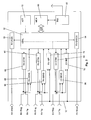
- stimulator 10 comprises a case 12 and header 14.
- the heart stimulator 10 is connected to three electrode leads, namely a right ventricular electrode lead for 16, a right atrial electrode lead 18 and a left ventricular electrode lead 20.
- the left ventricular electrode lead 20 is designed to pass trough the coronary sinus of heart 22.
- a typical electrode suitable for use with heart stimulator 10 is the electrode lead Corox+ UP/BB by the applicant.
- Left ventricular electrode lead 20 comprises a left ventricular tip electrode 24 at the distal end a left ventricular electrode lead 20 and a left ventricular ring electrode 26.
- Atrial electrode lead 18 comprises a right atrial tip electrode 28 at the distal end of right atrial electrode lead 18 and a right atrial ring electrode 30.
- the right ventricular electrode lead 16 comprises right ventricular tip electrode 32 at the distal end of right ventricular electrode lead 16 and a right ventricular ring electrode 34.
- heart stimulator 10 may be adapted to act as an implantable cardioverter/defibrillator (ICD)
- ventricular electrode lead 16 also exhibits a ventricular shock coil 36 for the delivery of defibrillation shocks to right ventricle 38 of heart 22 and an atrial shock coil 40 for the delivery of atrial defibrillation shocks to a right atrium 42 of heart 22.
- ICD implantable cardioverter/defibrillator
- Each electrode and shock coil of electrode leads 16 to 20 is separately connected to an electric circuit enclosed by case 12 of heart stimulator 10 by way of electrical contacts of a plug (not shown) at the proximal end of each electrode lead 16 to 20 and corresponding contacts (not shown) in header 14 of heart stimulator 10.
- Right atrial shock coil 40 is connected to right atrial shock generator 50 (see figure 2) that is controlled by a control unit 52 of heart stimulator 10.
- right ventricular shock coil 36 is connected to a right ventricular shock generator 54 that is also connected to control unit 52.
- Right atrial tip electrode 28 and right atrial ring electrode 30 are both connected to a right atrial stimulation pulse generator 56 and a right atrial sensing stage 58 that internal both connected to control unit 52.
- Right atrial stimulation pulse generator 56 is adapted to generate atrial stimulation pulses of sufficient strength to cause an excitation of atrial myocardium by an electrical pulse delivered via right atrial tip electrode 28 and right atrial ring electrode 30.
- means are provided to adapt the right atrial stimulation pulse strength to the stimulation threshold in the right atrium.
- Right atrial sensing stage 58 is adapted to pick up myocardial potentials indicating an intrinsic atrial excitation that corresponds to a natural atrial contraction. By way of right atrial sensing stage 58, it is possible to stimulate the right atrium 42 of heart 22 in a demand mode wherein a right atrial stimulation pulse is inhibited if an intrinsic atrial event (intrinsic atrial excitation) is sensed by right atrial sensing stage 58 prior to expiration of an atrial escape interval.
- an intrinsic atrial event intrinsic atrial excitation
- right ventricular ring electrode 34 and right ventricular tip electrode 32 are connected to right ventricular stimulation pulse generator 60 and to a right ventricular sensing stage 62 that in turn are connected to control unit 52.
- right ventricular tip electrode 32, right ventricular ring electrode 34, right ventricular stimulation generator 60 and right ventricular sensing stage 62 right ventricular stimulation pulses can be delivered in a demand mode to the right ventricle 38 of heart 22.
- left ventricular tip electrode 32 and left ventricular ring electrode 26 are connected to the left ventricular stimulation pulse generator 64 and the left ventricular sensing stage 66 that internal connected to control unit 52 and that allow for stimulating a left ventricle 70 of heart 22.
- Triggering and inhibition of delivery of stimulation pulses to the right atrium, the right ventricle or the left ventricle is controlled by control unit 52, in a manner known to the man skilled in the art.
- the timing that schedules delivery of stimulation pulses if needed is controlled by a number of intervals, that at least partly may depend on a hemodynamic demand of a patient that is sensed by means of an activity sensor 72 that is connected to control unit 52.
- Activity sensor 72 allows for rate adaptive pacing wherein a pacing rate (the rate of consecutive ventricular stimulation pulses for a duration of consecutive atrial stimulation pulses) depends on a physiological demand of a patient that is sensed by a way of activity sensor 72. Details of rate adaptation are known to the man skilled in the art but need not to be explained in detail in this description.
- an actual stimulation rate determines the timing from one (paced) heart cycle to another
- intervals like the atrioventricular delay interval and the interventricular delay interval determine the timing within one heart cycle.
- the right ventricle would be excited (either intrinsically or paced) at the end of the atrioventricular delay interval.
- a left ventricular contraction should follow the right ventricular contraction at the end of the interventricular delay interval. This shall include the case, wherein the right ventricle and the left ventricle are excited the same time resulting in an interventricular delay interval duration of zero. Also, it is possible that the left ventricle is excited prior to the right ventricle resulting in a negative interventricular delay interval duration.
- the atrial ventricular delay interval duration and the interventricular delay interval duration need to be adapted to an individual heart in order to achieve an optimized cardiac output.
- Heart stimulator 10 is adapted to determine an optimal atrioventricular delay interval duration and an optimal interventricular delay interval duration automatically. This is achieved by finding that atrioventricular interval and that interventricular interval that leads to minimum mechanical asynchrony between the right ventricular contraction and the corresponding left ventricular contraction.
- heart stimulator 10 comprises a right ventricular impedance measuring stage 74 and the left ventricular impedance measuring stage 76.
- the right ventricular impedance measuring stage 74 and the left ventricular impedance measuring stage 76 are adapted to simultaneously measure the time course of right ventricular impedance and left ventricular impedance, respectively, by way of sampling.
- Impedance measurement by impedance measuring stages 74 and 76 is started by control unit 52 either in synchrony with a right ventricular event or a left ventricular event, whatever comes first.
- a paced ventricular event corresponds to triggering any of the two ventricular stimulation pulse generators by control unit 52.
- a sensed ventricular event occurs, if one of ventricular sensing stages 62 or 66 records an intrinsic ventricular excitation.
- Impedance measurement of right ventricular impedance measuring stage 74 is carried out by injecting a sequence of 16 constant current pulses of alternating voltage via right ventricular tip electrode 32 and the heart stimulator's case 12. Each constant current pulse has a same strength between 100 ⁇ A and 400 ⁇ A. The voltage drop caused by each constant current pulse is measured via the same two electrodes, e.g. right ventricular tip electrode and case 32. Each voltage drop thus measured corresponds to a momentary right ventricular intracardiac impedance. The total sequence of 16 voltage samples represents the time course of the right ventricular intracardiac impedance. The time period between two samples is 16 ms corresponding to a sampling rate of 62.5 Hz.
- left ventricular impedance measuring stage 76 the time course of left ventricular impedance is sampled by left ventricular impedance measuring stage 76 via left ventricular tip electrode 24 and heart stimulator's case 12.
- Two voltage samples (representing a right ventricular impedance and a left ventricular impedance, respectively) measured at the same time form one pair of sample values.
- a total number of 16 pairs of sample values are obtained.
- the absolute difference between a voltage drop measured by the right ventricular impedance measuring stage 74 and the voltage drop measured by the left ventricular impedance measuring stage 76 is calculated. Thereafter, all 16 absolute differences thus determined are summed up. The sum thus obtained represents the absolute difference area AA between the time courses of the right ventricular intracardiac impedance and the left ventricular intracardiac impedance.
- a typical time course of the right ventricular impedance Z RV and the left ventricular intracardiac impedance Z LV is graphically represented by a continuous line each.
- the area enclosed between these two lines is the absolute difference area (absolute area; AA).
- the absolute difference area AA is marked by grey shading (hatching) in Fig. 3.
- the sixteen exemplary samples RVn1 to RVn16 taken by right ventricular impedance measuring stage 74 and the sixteen samples LVn1 to LVn16 taken by left ventricular impedance measuring stage 76 are marked in Fig. 3.
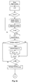
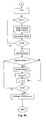
- Control unit 52 is adapted to optimize the atrioventricular delay interval duration and the interventricular delay interval duration by finding an atrioventricular delay interval duration and an interventricular delay interval duration that leads to a minimum AA.
- control unit 52 applies a number of different atrioventricular delay interval durations while maintaining an interventricular delay interval duration of 0 and determines the absolute difference area AA for each atrioventricular delay interval duration (AVD) thus tested.
- a total number of 8 atrioventricular delay interval durations between 50 to 450 ms is tested (50 ms, 100 ms, 150 ms, 200 ms, 300 ms, 350 ms, 400 ms, 450 ms).
- the atrioventricular delay interval duration AVD leading to a minimum absolute difference area AA is maintained while testing a number of interventricular delay interval durations between minus 70 ms and plus 70 ms in 5 to 10 ms steps.
- the algorithm for determining an optimum atrioventricular delay interval and an optimum interventricular delay interval can be summed up as follows:
- This algorithm is rerun every 3 to 7 days.
- the algorithm (optimization cycle) is run twice, one time, when the patient is at rest and the other time when the patient exhibits physical activity.
- the state of rest and the state of physical activity is determined by activity sensor 72 or by the impedance sensor 74.
- a total of four optimal delay interval durations is obtained, namely optimum atrioventricular delay interval duration at rest, an optimum atrioventricular delay interval duration under load, an optimum interventricular delay interval duration at rest and an optimum interventricular delay interval duration under load.
- These four values are stored in a memory 80 of heart stimulator 10.
- a minimum absolute difference area achieved when applying the optimum atrioventricular delay interval duration and the optimum interventricular delay interval duration is stored in memory 80 so it can be transmitted telemetrically to home monitoring service center via transceiver 82.
- the impedance signal from RV and LV in real-time is transmitted to a programmer in order to enable a physician to review the process of automatic optimization of VVD and AVD during follow-up scenarios.
Landscapes
- Health & Medical Sciences (AREA)
- Cardiology (AREA)
- Heart & Thoracic Surgery (AREA)
- Life Sciences & Earth Sciences (AREA)
- Public Health (AREA)
- General Health & Medical Sciences (AREA)
- Engineering & Computer Science (AREA)
- Biomedical Technology (AREA)
- Nuclear Medicine, Radiotherapy & Molecular Imaging (AREA)
- Radiology & Medical Imaging (AREA)
- Animal Behavior & Ethology (AREA)
- Veterinary Medicine (AREA)
- Biophysics (AREA)
- Physiology (AREA)
- Hematology (AREA)
- Hospice & Palliative Care (AREA)
- Electrotherapy Devices (AREA)
- Medicines Containing Material From Animals Or Micro-Organisms (AREA)
- Prostheses (AREA)
Applications Claiming Priority (1)
| Application Number | Priority Date | Filing Date | Title |
|---|---|---|---|
| US11/537,049 US7640058B2 (en) | 2006-09-29 | 2006-09-29 | Biventricular heart stimulator |
Publications (2)
| Publication Number | Publication Date |
|---|---|
| EP1905480A1 true EP1905480A1 (fr) | 2008-04-02 |
| EP1905480B1 EP1905480B1 (fr) | 2010-02-17 |
Family
ID=38894095
Family Applications (1)
| Application Number | Title | Priority Date | Filing Date |
|---|---|---|---|
| EP07017198A Not-in-force EP1905480B1 (fr) | 2006-09-29 | 2007-09-03 | Stimulateur cardiaque biventriculaire |
Country Status (4)
| Country | Link |
|---|---|
| US (1) | US7640058B2 (fr) |
| EP (1) | EP1905480B1 (fr) |
| AT (1) | ATE457776T1 (fr) |
| DE (1) | DE602007004786D1 (fr) |
Cited By (2)
| Publication number | Priority date | Publication date | Assignee | Title |
|---|---|---|---|---|
| EP2429394A4 (fr) * | 2009-05-13 | 2013-08-21 | St Jude Medical | Dispositif médical et procédé permettant de déterminer une mesure de désynchronicité |
| WO2017102780A1 (fr) * | 2015-12-18 | 2017-06-22 | Sorin Crm Sas | Dispositif médical implantable actif de type resynchroniseur cardiaque avec adaptation dynamique du délai atrioventriculaire en fonction d'un degré de fusion détecté et quantifié |
Families Citing this family (6)
| Publication number | Priority date | Publication date | Assignee | Title |
|---|---|---|---|---|
| US7890163B2 (en) * | 2006-10-19 | 2011-02-15 | Cardiac Pacemakers, Inc. | Method and apparatus for detecting fibrillation using cardiac local impedance |
| US7840267B2 (en) * | 2007-03-23 | 2010-11-23 | Cardiac Pacemakers, Inc. | Closed-loop resynchronization therapy for mechanical dyssynchrony |
| WO2010074611A1 (fr) * | 2008-12-22 | 2010-07-01 | St. Jude Medical Ab | Dispositif médical implantable et procédé de surveillance de la synchronicité des ventricules d'un coeur |
| EP2403591B1 (fr) * | 2009-02-27 | 2015-07-15 | Medtronic, Inc | Système de stimulation biventriculaire conditionnelle |
| EP2383016B1 (fr) | 2010-04-29 | 2017-08-23 | BIOTRONIK SE & Co. KG | Système d'entretien pour l'entretien d'un agencement de stockage d'énergie |
| US12428543B2 (en) | 2021-05-18 | 2025-09-30 | Ticona Llc | Connected medical device containing a liquid crystalline polymer composition having a low dielectric constant |
Citations (7)
| Publication number | Priority date | Publication date | Assignee | Title |
|---|---|---|---|---|
| US4303075A (en) | 1980-02-11 | 1981-12-01 | Mieczyslaw Mirowski | Method and apparatus for maximizing stroke volume through atrioventricular pacing using implanted cardioverter/pacer |
| US20010012953A1 (en) | 1999-12-17 | 2001-08-09 | Molin Renzo Dal | Active implantable medical device, in particular a pacemaker, defibrillator and/or cardiovertor of the multisite type providing resynchronization of the ventricles |
| EP1260246A2 (fr) * | 2001-05-25 | 2002-11-27 | Pacesetter, Inc. | Procédé et système de stimulation double chambre utilisant un retard entre impulsions adaptée dynamiquement |
| US20030045805A1 (en) * | 2001-08-30 | 2003-03-06 | Medtronic, Inc. | Ischemia detection |
| US20050049646A1 (en) * | 2003-09-01 | 2005-03-03 | Biotronik Gmbh & Co. Kg | Intracardial impedance measuring arrangement |
| US20050131469A1 (en) | 2003-12-16 | 2005-06-16 | Leonard Bloom | Hemodynamic optimization system for biventricular implants |
| US20060079940A1 (en) * | 2004-08-04 | 2006-04-13 | Ela Medical S.A. | Active implantable medical device which includes a mode of resynchronization of the ventricular contractions for the treatment of the cardiac insufficiency |
Family Cites Families (5)
| Publication number | Priority date | Publication date | Assignee | Title |
|---|---|---|---|---|
| US4217913A (en) * | 1977-10-10 | 1980-08-19 | Medtronic, Inc. | Body-implantable lead with protected, extendable tissue securing means |
| US6819959B1 (en) * | 2001-11-21 | 2004-11-16 | Pacesetter, Inc. | Extendable/retractable screw-in tip design with an improved thread/screw mechanism |
| US7228174B2 (en) * | 2002-04-29 | 2007-06-05 | Medtronics, Inc. | Algorithm for the automatic determination of optimal AV an VV intervals |
| DE10257156A1 (de) * | 2002-12-02 | 2004-06-17 | Biotronik Meß- und Therapiegeräte GmbH & Co. Ingenieurbüro Berlin | Herzschrittmacher |
| US20060271121A1 (en) * | 2005-05-25 | 2006-11-30 | Cardiac Pacemakers, Inc. | Closed loop impedance-based cardiac resynchronization therapy systems, devices, and methods |
-
2006
- 2006-09-29 US US11/537,049 patent/US7640058B2/en not_active Expired - Fee Related
-
2007
- 2007-09-03 AT AT07017198T patent/ATE457776T1/de not_active IP Right Cessation
- 2007-09-03 DE DE602007004786T patent/DE602007004786D1/de active Active
- 2007-09-03 EP EP07017198A patent/EP1905480B1/fr not_active Not-in-force
Patent Citations (8)
| Publication number | Priority date | Publication date | Assignee | Title |
|---|---|---|---|---|
| US4303075A (en) | 1980-02-11 | 1981-12-01 | Mieczyslaw Mirowski | Method and apparatus for maximizing stroke volume through atrioventricular pacing using implanted cardioverter/pacer |
| US20010012953A1 (en) | 1999-12-17 | 2001-08-09 | Molin Renzo Dal | Active implantable medical device, in particular a pacemaker, defibrillator and/or cardiovertor of the multisite type providing resynchronization of the ventricles |
| EP1260246A2 (fr) * | 2001-05-25 | 2002-11-27 | Pacesetter, Inc. | Procédé et système de stimulation double chambre utilisant un retard entre impulsions adaptée dynamiquement |
| US20030045805A1 (en) * | 2001-08-30 | 2003-03-06 | Medtronic, Inc. | Ischemia detection |
| US20050049646A1 (en) * | 2003-09-01 | 2005-03-03 | Biotronik Gmbh & Co. Kg | Intracardial impedance measuring arrangement |
| US20050131469A1 (en) | 2003-12-16 | 2005-06-16 | Leonard Bloom | Hemodynamic optimization system for biventricular implants |
| US20060079940A1 (en) * | 2004-08-04 | 2006-04-13 | Ela Medical S.A. | Active implantable medical device which includes a mode of resynchronization of the ventricular contractions for the treatment of the cardiac insufficiency |
| WO2006055202A2 (fr) * | 2004-11-16 | 2006-05-26 | Cohen Todd J | Systeme d'optimisation hemodynamique pour implants biventriculaires |
Cited By (3)
| Publication number | Priority date | Publication date | Assignee | Title |
|---|---|---|---|---|
| EP2429394A4 (fr) * | 2009-05-13 | 2013-08-21 | St Jude Medical | Dispositif médical et procédé permettant de déterminer une mesure de désynchronicité |
| WO2017102780A1 (fr) * | 2015-12-18 | 2017-06-22 | Sorin Crm Sas | Dispositif médical implantable actif de type resynchroniseur cardiaque avec adaptation dynamique du délai atrioventriculaire en fonction d'un degré de fusion détecté et quantifié |
| US11027134B2 (en) | 2015-12-18 | 2021-06-08 | Sorin Crm Sas | Active implantable medical device such as a cardiac resynchroniser with dynamic adaptation of an atrioventricular delay depending on a detected and quantified degree of fusion |
Also Published As
| Publication number | Publication date |
|---|---|
| ATE457776T1 (de) | 2010-03-15 |
| US20080082134A1 (en) | 2008-04-03 |
| EP1905480B1 (fr) | 2010-02-17 |
| US7640058B2 (en) | 2009-12-29 |
| DE602007004786D1 (de) | 2010-04-01 |
Similar Documents
| Publication | Publication Date | Title |
|---|---|---|
| US8509896B2 (en) | Biventricular cardiac stimulator | |
| US6959214B2 (en) | Implantable medical device for measuring mechanical heart function | |
| EP2809394B1 (fr) | Système pour la thérapie de resynchronisation cardiaque basée sur une indication de la conduction atrioventriculaire intrinsèque | |
| EP3463563B1 (fr) | Commande à base d'électrogramme de thérapie de resynchronisation cardiaque | |
| EP1735049B1 (fr) | Optimisation en temps reel de la sequence de synchronisation ventriculaire de droite a gauche dans la stimulation biventriculaire des patients souffrant d'insuffisance cardiaque | |
| EP3737460B1 (fr) | Thérapie de resynchronisation cardiaque adaptative | |
| US7844335B2 (en) | Implantable medical device and method for LV coronary sinus lead implant site optimization | |
| EP1905480B1 (fr) | Stimulateur cardiaque biventriculaire | |
| CN111886048B (zh) | 在心室起搏治疗期间的希氏束起搏夺获的监测 | |
| EP1923097A1 (fr) | Stimulateur cardiaque | |
| US20070255327A1 (en) | Implantable Medical Device with Electromechanical Delay Measurement for Lead Position and Ventricular | |
| US20220001185A1 (en) | Cardiac resynchronization therapy diagnostics | |
| WO2007079326A2 (fr) | Traitement numerique des signaux disposant d'une frequence d'echantillonnage variable | |
| JP2022501085A (ja) | 心房からの心室心臓治療における捕捉 | |
| CN112566691B (zh) | 用于标识和调整失有效心脏再同步治疗的系统 | |
| US11219774B2 (en) | Ventricular leadless implantable medical device with dual chamber sensing and method for same | |
| US8391978B2 (en) | Method and apparatus for adjusting sensitivity using intracardiac pressure data | |
| EP1800709A1 (fr) | Stimulateur cardiaque | |
| EP4153295B1 (fr) | Dispositif médical implantable pour stimuler un coeur humain ou animal en utilisant une évaluation de signaux entre son électrode et une autre électrode | |
| EP4188531B1 (fr) | Sélection de thérapie de stimulation permettant le traitement de l'insuffisance cardiaque | |
| US9026209B2 (en) | Ventricular cardiac stimulator | |
| EP2767222A1 (fr) | Dispositif implantable de surveillance cardiaque | |
| US8260420B2 (en) | Method and device for processing cardiac signals |
Legal Events
| Date | Code | Title | Description |
|---|---|---|---|
| PUAI | Public reference made under article 153(3) epc to a published international application that has entered the european phase |
Free format text: ORIGINAL CODE: 0009012 |
|
| AK | Designated contracting states |
Kind code of ref document: A1 Designated state(s): AT BE BG CH CY CZ DE DK EE ES FI FR GB GR HU IE IS IT LI LT LU LV MC MT NL PL PT RO SE SI SK TR |
|
| AX | Request for extension of the european patent |
Extension state: AL BA HR MK YU |
|
| 17P | Request for examination filed |
Effective date: 20080911 |
|
| 17Q | First examination report despatched |
Effective date: 20081015 |
|
| AKX | Designation fees paid |
Designated state(s): AT BE BG CH CY CZ DE DK EE ES FI FR GB GR HU IE IS IT LI LT LU LV MC MT NL PL PT RO SE SI SK TR |
|
| GRAP | Despatch of communication of intention to grant a patent |
Free format text: ORIGINAL CODE: EPIDOSNIGR1 |
|
| GRAS | Grant fee paid |
Free format text: ORIGINAL CODE: EPIDOSNIGR3 |
|
| GRAA | (expected) grant |
Free format text: ORIGINAL CODE: 0009210 |
|
| AK | Designated contracting states |
Kind code of ref document: B1 Designated state(s): AT BE BG CH CY CZ DE DK EE ES FI FR GB GR HU IE IS IT LI LT LU LV MC MT NL PL PT RO SE SI SK TR |
|
| REG | Reference to a national code |
Ref country code: GB Ref legal event code: FG4D |
|
| REG | Reference to a national code |
Ref country code: CH Ref legal event code: EP |
|
| REG | Reference to a national code |
Ref country code: IE Ref legal event code: FG4D |
|
| REF | Corresponds to: |
Ref document number: 602007004786 Country of ref document: DE Date of ref document: 20100401 Kind code of ref document: P |
|
| REG | Reference to a national code |
Ref country code: SE Ref legal event code: TRGR |
|
| REG | Reference to a national code |
Ref country code: NL Ref legal event code: VDEP Effective date: 20100217 |
|
| LTIE | Lt: invalidation of european patent or patent extension |
Effective date: 20100217 |
|
| PG25 | Lapsed in a contracting state [announced via postgrant information from national office to epo] |
Ref country code: ES Free format text: LAPSE BECAUSE OF FAILURE TO SUBMIT A TRANSLATION OF THE DESCRIPTION OR TO PAY THE FEE WITHIN THE PRESCRIBED TIME-LIMIT Effective date: 20100528 Ref country code: LT Free format text: LAPSE BECAUSE OF FAILURE TO SUBMIT A TRANSLATION OF THE DESCRIPTION OR TO PAY THE FEE WITHIN THE PRESCRIBED TIME-LIMIT Effective date: 20100217 Ref country code: PT Free format text: LAPSE BECAUSE OF FAILURE TO SUBMIT A TRANSLATION OF THE DESCRIPTION OR TO PAY THE FEE WITHIN THE PRESCRIBED TIME-LIMIT Effective date: 20100617 Ref country code: IS Free format text: LAPSE BECAUSE OF FAILURE TO SUBMIT A TRANSLATION OF THE DESCRIPTION OR TO PAY THE FEE WITHIN THE PRESCRIBED TIME-LIMIT Effective date: 20100617 |
|
| PG25 | Lapsed in a contracting state [announced via postgrant information from national office to epo] |
Ref country code: LV Free format text: LAPSE BECAUSE OF FAILURE TO SUBMIT A TRANSLATION OF THE DESCRIPTION OR TO PAY THE FEE WITHIN THE PRESCRIBED TIME-LIMIT Effective date: 20100217 Ref country code: FI Free format text: LAPSE BECAUSE OF FAILURE TO SUBMIT A TRANSLATION OF THE DESCRIPTION OR TO PAY THE FEE WITHIN THE PRESCRIBED TIME-LIMIT Effective date: 20100217 Ref country code: SI Free format text: LAPSE BECAUSE OF FAILURE TO SUBMIT A TRANSLATION OF THE DESCRIPTION OR TO PAY THE FEE WITHIN THE PRESCRIBED TIME-LIMIT Effective date: 20100217 Ref country code: AT Free format text: LAPSE BECAUSE OF FAILURE TO SUBMIT A TRANSLATION OF THE DESCRIPTION OR TO PAY THE FEE WITHIN THE PRESCRIBED TIME-LIMIT Effective date: 20100217 Ref country code: PL Free format text: LAPSE BECAUSE OF FAILURE TO SUBMIT A TRANSLATION OF THE DESCRIPTION OR TO PAY THE FEE WITHIN THE PRESCRIBED TIME-LIMIT Effective date: 20100217 |
|
| PG25 | Lapsed in a contracting state [announced via postgrant information from national office to epo] |
Ref country code: NL Free format text: LAPSE BECAUSE OF FAILURE TO SUBMIT A TRANSLATION OF THE DESCRIPTION OR TO PAY THE FEE WITHIN THE PRESCRIBED TIME-LIMIT Effective date: 20100217 Ref country code: GR Free format text: LAPSE BECAUSE OF FAILURE TO SUBMIT A TRANSLATION OF THE DESCRIPTION OR TO PAY THE FEE WITHIN THE PRESCRIBED TIME-LIMIT Effective date: 20100518 Ref country code: RO Free format text: LAPSE BECAUSE OF FAILURE TO SUBMIT A TRANSLATION OF THE DESCRIPTION OR TO PAY THE FEE WITHIN THE PRESCRIBED TIME-LIMIT Effective date: 20100217 Ref country code: EE Free format text: LAPSE BECAUSE OF FAILURE TO SUBMIT A TRANSLATION OF THE DESCRIPTION OR TO PAY THE FEE WITHIN THE PRESCRIBED TIME-LIMIT Effective date: 20100217 Ref country code: CY Free format text: LAPSE BECAUSE OF FAILURE TO SUBMIT A TRANSLATION OF THE DESCRIPTION OR TO PAY THE FEE WITHIN THE PRESCRIBED TIME-LIMIT Effective date: 20100217 Ref country code: BE Free format text: LAPSE BECAUSE OF FAILURE TO SUBMIT A TRANSLATION OF THE DESCRIPTION OR TO PAY THE FEE WITHIN THE PRESCRIBED TIME-LIMIT Effective date: 20100217 |
|
| PG25 | Lapsed in a contracting state [announced via postgrant information from national office to epo] |
Ref country code: BG Free format text: LAPSE BECAUSE OF FAILURE TO SUBMIT A TRANSLATION OF THE DESCRIPTION OR TO PAY THE FEE WITHIN THE PRESCRIBED TIME-LIMIT Effective date: 20100517 Ref country code: SK Free format text: LAPSE BECAUSE OF FAILURE TO SUBMIT A TRANSLATION OF THE DESCRIPTION OR TO PAY THE FEE WITHIN THE PRESCRIBED TIME-LIMIT Effective date: 20100217 Ref country code: CZ Free format text: LAPSE BECAUSE OF FAILURE TO SUBMIT A TRANSLATION OF THE DESCRIPTION OR TO PAY THE FEE WITHIN THE PRESCRIBED TIME-LIMIT Effective date: 20100217 |
|
| PLBE | No opposition filed within time limit |
Free format text: ORIGINAL CODE: 0009261 |
|
| STAA | Information on the status of an ep patent application or granted ep patent |
Free format text: STATUS: NO OPPOSITION FILED WITHIN TIME LIMIT |
|
| 26N | No opposition filed |
Effective date: 20101118 |
|
| PG25 | Lapsed in a contracting state [announced via postgrant information from national office to epo] |
Ref country code: DK Free format text: LAPSE BECAUSE OF FAILURE TO SUBMIT A TRANSLATION OF THE DESCRIPTION OR TO PAY THE FEE WITHIN THE PRESCRIBED TIME-LIMIT Effective date: 20100217 |
|
| PG25 | Lapsed in a contracting state [announced via postgrant information from national office to epo] |
Ref country code: IT Free format text: LAPSE BECAUSE OF FAILURE TO SUBMIT A TRANSLATION OF THE DESCRIPTION OR TO PAY THE FEE WITHIN THE PRESCRIBED TIME-LIMIT Effective date: 20100217 |
|
| PG25 | Lapsed in a contracting state [announced via postgrant information from national office to epo] |
Ref country code: MC Free format text: LAPSE BECAUSE OF NON-PAYMENT OF DUE FEES Effective date: 20100930 |
|
| PG25 | Lapsed in a contracting state [announced via postgrant information from national office to epo] |
Ref country code: MT Free format text: LAPSE BECAUSE OF FAILURE TO SUBMIT A TRANSLATION OF THE DESCRIPTION OR TO PAY THE FEE WITHIN THE PRESCRIBED TIME-LIMIT Effective date: 20100217 |
|
| PG25 | Lapsed in a contracting state [announced via postgrant information from national office to epo] |
Ref country code: HU Free format text: LAPSE BECAUSE OF FAILURE TO SUBMIT A TRANSLATION OF THE DESCRIPTION OR TO PAY THE FEE WITHIN THE PRESCRIBED TIME-LIMIT Effective date: 20100818 Ref country code: LU Free format text: LAPSE BECAUSE OF NON-PAYMENT OF DUE FEES Effective date: 20100903 |
|
| PG25 | Lapsed in a contracting state [announced via postgrant information from national office to epo] |
Ref country code: TR Free format text: LAPSE BECAUSE OF FAILURE TO SUBMIT A TRANSLATION OF THE DESCRIPTION OR TO PAY THE FEE WITHIN THE PRESCRIBED TIME-LIMIT Effective date: 20100217 |
|
| PGFP | Annual fee paid to national office [announced via postgrant information from national office to epo] |
Ref country code: SE Payment date: 20120920 Year of fee payment: 6 Ref country code: GB Payment date: 20120920 Year of fee payment: 6 |
|
| REG | Reference to a national code |
Ref country code: SE Ref legal event code: EUG |
|
| PG25 | Lapsed in a contracting state [announced via postgrant information from national office to epo] |
Ref country code: SE Free format text: LAPSE BECAUSE OF NON-PAYMENT OF DUE FEES Effective date: 20130904 |
|
| GBPC | Gb: european patent ceased through non-payment of renewal fee |
Effective date: 20130903 |
|
| PG25 | Lapsed in a contracting state [announced via postgrant information from national office to epo] |
Ref country code: GB Free format text: LAPSE BECAUSE OF NON-PAYMENT OF DUE FEES Effective date: 20130903 |
|
| REG | Reference to a national code |
Ref country code: FR Ref legal event code: PLFP Year of fee payment: 10 |
|
| PGFP | Annual fee paid to national office [announced via postgrant information from national office to epo] |
Ref country code: DE Payment date: 20160923 Year of fee payment: 10 Ref country code: CH Payment date: 20160926 Year of fee payment: 10 Ref country code: IE Payment date: 20160922 Year of fee payment: 10 |
|
| PGFP | Annual fee paid to national office [announced via postgrant information from national office to epo] |
Ref country code: FR Payment date: 20160922 Year of fee payment: 10 |
|
| REG | Reference to a national code |
Ref country code: DE Ref legal event code: R119 Ref document number: 602007004786 Country of ref document: DE |
|
| REG | Reference to a national code |
Ref country code: CH Ref legal event code: PL |
|
| REG | Reference to a national code |
Ref country code: IE Ref legal event code: MM4A |
|
| REG | Reference to a national code |
Ref country code: FR Ref legal event code: ST Effective date: 20180531 |
|
| PG25 | Lapsed in a contracting state [announced via postgrant information from national office to epo] |
Ref country code: DE Free format text: LAPSE BECAUSE OF NON-PAYMENT OF DUE FEES Effective date: 20180404 Ref country code: CH Free format text: LAPSE BECAUSE OF NON-PAYMENT OF DUE FEES Effective date: 20170930 Ref country code: IE Free format text: LAPSE BECAUSE OF NON-PAYMENT OF DUE FEES Effective date: 20170903 Ref country code: LI Free format text: LAPSE BECAUSE OF NON-PAYMENT OF DUE FEES Effective date: 20170930 |
|
| PG25 | Lapsed in a contracting state [announced via postgrant information from national office to epo] |
Ref country code: FR Free format text: LAPSE BECAUSE OF NON-PAYMENT OF DUE FEES Effective date: 20171002 |