EP1905628A2 - Support structure for vehicular slide door - Google Patents
Support structure for vehicular slide door Download PDFInfo
- Publication number
- EP1905628A2 EP1905628A2 EP07017320A EP07017320A EP1905628A2 EP 1905628 A2 EP1905628 A2 EP 1905628A2 EP 07017320 A EP07017320 A EP 07017320A EP 07017320 A EP07017320 A EP 07017320A EP 1905628 A2 EP1905628 A2 EP 1905628A2
- Authority
- EP
- European Patent Office
- Prior art keywords
- slide door
- wall
- horizontal wall
- support structure
- mounting portion
- Prior art date
- Legal status (The legal status is an assumption and is not a legal conclusion. Google has not performed a legal analysis and makes no representation as to the accuracy of the status listed.)
- Granted
Links
Images




Classifications
-
- B—PERFORMING OPERATIONS; TRANSPORTING
- B60—VEHICLES IN GENERAL
- B60J—WINDOWS, WINDSCREENS, NON-FIXED ROOFS, DOORS, OR SIMILAR DEVICES FOR VEHICLES; REMOVABLE EXTERNAL PROTECTIVE COVERINGS SPECIALLY ADAPTED FOR VEHICLES
- B60J5/00—Doors
- B60J5/04—Doors arranged at the vehicle sides
- B60J5/06—Doors arranged at the vehicle sides slidable; foldable
-
- E—FIXED CONSTRUCTIONS
- E05—LOCKS; KEYS; WINDOW OR DOOR FITTINGS; SAFES
- E05D—HINGES OR SUSPENSION DEVICES FOR DOORS, WINDOWS OR WINGS
- E05D15/00—Suspension arrangements for wings
- E05D15/06—Suspension arrangements for wings for wings sliding horizontally more or less in their own plane
- E05D15/0621—Details, e.g. suspension or supporting guides
- E05D15/0626—Details, e.g. suspension or supporting guides for wings suspended at the top
- E05D15/063—Details, e.g. suspension or supporting guides for wings suspended at the top on wheels with fixed axis
-
- E—FIXED CONSTRUCTIONS
- E05—LOCKS; KEYS; WINDOW OR DOOR FITTINGS; SAFES
- E05D—HINGES OR SUSPENSION DEVICES FOR DOORS, WINDOWS OR WINGS
- E05D15/00—Suspension arrangements for wings
- E05D15/06—Suspension arrangements for wings for wings sliding horizontally more or less in their own plane
- E05D15/10—Suspension arrangements for wings for wings sliding horizontally more or less in their own plane movable out of one plane into a second parallel plane
- E05D15/1042—Suspension arrangements for wings for wings sliding horizontally more or less in their own plane movable out of one plane into a second parallel plane with transversely moving carriage
- E05D15/1047—Suspension arrangements for wings for wings sliding horizontally more or less in their own plane movable out of one plane into a second parallel plane with transversely moving carriage specially adapted for vehicles
-
- E—FIXED CONSTRUCTIONS
- E05—LOCKS; KEYS; WINDOW OR DOOR FITTINGS; SAFES
- E05D—HINGES OR SUSPENSION DEVICES FOR DOORS, WINDOWS OR WINGS
- E05D15/00—Suspension arrangements for wings
- E05D15/06—Suspension arrangements for wings for wings sliding horizontally more or less in their own plane
- E05D15/10—Suspension arrangements for wings for wings sliding horizontally more or less in their own plane movable out of one plane into a second parallel plane
- E05D15/1042—Suspension arrangements for wings for wings sliding horizontally more or less in their own plane movable out of one plane into a second parallel plane with transversely moving carriage
- E05D2015/1055—Suspension arrangements for wings for wings sliding horizontally more or less in their own plane movable out of one plane into a second parallel plane with transversely moving carriage with slanted or curved track sections or cams
- E05D2015/1057—Suspension arrangements for wings for wings sliding horizontally more or less in their own plane movable out of one plane into a second parallel plane with transversely moving carriage with slanted or curved track sections or cams the carriage swinging or rotating in those track sections
-
- E—FIXED CONSTRUCTIONS
- E05—LOCKS; KEYS; WINDOW OR DOOR FITTINGS; SAFES
- E05Y—INDEXING SCHEME ASSOCIATED WITH SUBCLASSES E05D AND E05F, RELATING TO CONSTRUCTION ELEMENTS, ELECTRIC CONTROL, POWER SUPPLY, POWER SIGNAL OR TRANSMISSION, USER INTERFACES, MOUNTING OR COUPLING, DETAILS, ACCESSORIES, AUXILIARY OPERATIONS NOT OTHERWISE PROVIDED FOR, APPLICATION THEREOF
- E05Y2201/00—Constructional elements; Accessories therefor
- E05Y2201/60—Suspension or transmission members; Accessories therefor
- E05Y2201/622—Suspension or transmission members elements
- E05Y2201/64—Carriers
-
- E—FIXED CONSTRUCTIONS
- E05—LOCKS; KEYS; WINDOW OR DOOR FITTINGS; SAFES
- E05Y—INDEXING SCHEME ASSOCIATED WITH SUBCLASSES E05D AND E05F, RELATING TO CONSTRUCTION ELEMENTS, ELECTRIC CONTROL, POWER SUPPLY, POWER SIGNAL OR TRANSMISSION, USER INTERFACES, MOUNTING OR COUPLING, DETAILS, ACCESSORIES, AUXILIARY OPERATIONS NOT OTHERWISE PROVIDED FOR, APPLICATION THEREOF
- E05Y2900/00—Application of doors, windows, wings or fittings thereof
- E05Y2900/50—Application of doors, windows, wings or fittings thereof for vehicles
- E05Y2900/53—Type of wing
- E05Y2900/531—Doors
Definitions
- the present invention relates to a support structure for a vehicular slide door.
- a slide door which slides in the longitudinal direction along a side of a vehicle body.
- the vehicle body is provided at its three locations (an upper portion, a central portion and a lower portion) with guide rails extending in the longitudinal direction.
- a roller base is attached to each of the guide rails.
- the roller base moves in the longitudinal direction along the guide rail.
- Base plates (brackets) are mounted on the slide door in correspondence with the upper, central and lower guide rails such that the base plates project toward the vehicle body. Because the base plates are fastened to the roller bases, the slide door can move in the longitudinal direction along the guide rails.
- Each base plate is formed at its one end with a long hole extending in the widthwise direction of the vehicle, and each roller base is formed with a bolt mounting hole.
- the base plate and the roller base are fastened to each other by threadedly engaging a bolt which penetrates the long hole with the bolt mounting hole.
- the fastening position therebetween is adjusted along the longitudinal direction of the long hole within a range where the bolt which is temporarily inserted into the bolt mounting hole relatively moves along the long hole.
- the mounting position of the slide door with respect to the vehicle body is adjusted (for example, Japanese Patent Application Laid-open No. 2006-2383 ).
- a first aspect of the present invention provides a support structure for a vehicular slide door comprising a bracket fixed to the slide door, and a connection assembly in which a roller holder for holding a roller which rolls along a guide rail provided on a vehicle body and a mounting portion to which the bracket is fastened are relatively turnably connected to each other through a connecting unit including a connection shaft, wherein the bracket includes a substantially horizontally extending horizontal wall, the horizontal wall is formed with a notch groove which is formed by cutting a tip end of the horizontal wall on the side of the vehicle body substantially along an approaching/separating direction between the vehicle body and the slide door, and the connecting unit is movably inserted into the notch groove, and the mounting portion and the horizontal wall are fastened to each other in a state where they are superposed on each other.
- connection assembly has a portion which vertically sandwiches the horizontal wall.
- the mounting portion has two plates for vertically sandwiching the horizontal wall.
- the two plates are fastened to the horizontal wall by a common fastening tool.
- the two plates are fastened to the horizontal wall by separate fastening tools, the fastening tools which fasten the connection shaft, the plates and the horizontal wall to each other are disposed substantially straightly along the approaching/separating direction.
- the mounting portion is provided with a projection for limiting a turning movement of the roller holder in one direction.
- the roller holder includes an upper wall and a lower wall which are parallel to each other substantially horizontally, and a vertical wall which connects vehicle body side ends of the upper wall and the lower wall, the mounting portion is disposed at a position between the upper wall and the lower wall, the connecting unit includes a holding cylinder which is fixed to the mounting portion at a position between the upper wall and the lower wall and which turnably holds the connection shaft, an upper end of the connection shaft is fixed to the upper wall, a lower end of the connection shaft is fixed to the lower wall, and the holding cylinder and superposed portions of the mounting portion and the horizontal wall are sandwiched between the upper wall and the lowerwall in a state where the mounting portion and the horizontal wall are fastened to each other.
- Fig. 1 is a perspective view showing an automobile employing a support structure for a vehicular slide door according to a first embodiment of the present invention.
- Fig. 2 is a sectional view taken along a line II-II in Fig. 1.
- Fig. 3 is a perspective view of a roller holder included in the support structure for a vehicular slide door.
- Fig. 4 is a plan view of the support structure for a vehicular slide door.
- Fig. 5 is aplanviewof the support structure for a vehicular slide door before fastening.
- Fig. 6 is a sectional view taken along a line VI-VI in Fig. 4.
- Fig. 1 is a perspective view showing an automobile employing a support structure for a vehicular slide door according to a first embodiment of the present invention.
- Fig. 2 is a sectional view taken along a line II-II in Fig. 1.
- Fig. 3 is a perspective view of a roller holder included in the support structure for
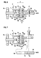
- FIG. 7 is a sectional view of the support structure for a vehicular slide door before fastening at the same position as that shown in Fig. 6.
- a symbol X represents an approaching/separating direction between the vehicle body and the slide door
- a symbol Y represents an extending direction of the guide rail.
- an upper portion, a central portion and a lower portion of a side of the vehicle body 1 are respectively provided with guide rails 2U, 2M and 2L extending in the longitudinal direction.
- a slide door 3 is supported by the guide rails 2U, 2M and 2L such that the slide door 3 canmove in the longitudinal direction, and the slide door 3 opens and closes an opening formed in the side of the vehicle body 1.
- the three guide rails 2U, 2M and 2L have substantially the same support structure for a vehicular slide door according to the present embodiment and thus, only a structure concerning the lower guide rail 2L will be explained.
- the guide rail 2L extends horizontally and straightly along the longitudinal direction as a whole. However, a front end 2a of the guide rail 2L is gently curved inward in the widthwise direction of the vehicle and extending obliquely forward.
- the slide door 3 is mounted on the vehicle body 1 through a connection assembly 4.
- the connection assembly 4 longitudinally moves along the guide rail 2L.
- the connection assembly 4 includes a plate 6 as a mounting portion on which a bracket 5 fixed to the slide door 3 is mounted.
- the connection assembly 4 also includes a roller holder 7 which rotatably holds rollers 8a and 8b which roll along the guide rail 2L, and a connecting unit 9 which connects the plate 6 and the roller holder 7 with each other such that they relatively turn with respect to each other.
- the guide rail 2L has a substantiallyC-shaped cross section (not shown) which opens toward the slide door 3. If the rollers 8a and 8b roll in the guide rail 2L, the connection assembly 4 slides along the guide rail 2L, and the slide door 3 which is fixed to the connection assembly 4 longitudinally moves.
- the roller holder 7 includes a base 10 which is formed by appropriately bending a plate member having a substantially constant thickness.
- the base 10 includes an upper wall 10a and a lower wall 10b which are extending substantially horizontally and which are in parallel to each other, and a vertical wall 10c which extends substantially vertically and which connects vehicle body sides of the upper wall 10a and the lower wall 10b with each other .
- the vertical wall 10c is provided at its opposite sides in the longitudinal direction (extending direction of the guide rail 2L) with tongue-like lateral walls 10d and 10d extending horizontally toward the vehicle body 1 stepwisely from an end edge of the upper wall 10a on the side of the vehicle body 1.
- Substantially circular through holes 11a and 11b are formed in the upper wall 10a and the lower wall 10b on the side of the slide door 3.
- the through holes 11a and 11b are superposed on each other in the vertical direction.
- a connection shaft 13 extending vertically is inserted through the through holes 11a and 11b.
- a shaft 12a extending horizontally toward the vehicle body 1 is mounted on the vertical wall 10c.
- the roller 8a is rotatably supported by the shaft 12a, and the roller 8a rolls on a bottom surface in the cross section of the guide rail 2L.
- Shafts 12b extending vertically upward are mounted on the lateral walls 10d and 10d, respectively.
- the rollers 8b are rotatably supported by the shafts 12b, respectively, and the rollers 8b roll on the side surface in the cross section of the guide rail 2L.
- the connecting unit 9 includes the substantially vertically extending connection shaft 13, and a holding cylinder 14 through which the connection shaft 13 passes.
- connection shaft 13 vertically penetrates the through holes 11a and 11b formed in the upper wall 10a and the lower wall 10b of the base 10.
- a portion of the connection shaft 13 projecting upward from the through hole 11a and a portion of the connection shaft 13 projecting downward from the through hole 11b are swaged and expanded radially outward, and the expanded portions vertically sandwich the upper wall 10a and the lower wall 10b, thereby fixing (retaining) the connection shaft 13 to the base 10.
- connection shaft 13 is turnably inserted through the holding cylinder 14 (through hole 14a).
- the holding cylinder 14 is disposed such that the holding cylinder 14 is sandwiched between the upper wall 10a and the lower wall 10b of the base 10 in the axial direction.
- An upper end is inserted into the through hole 6a formed in the plate 6 and is mounted on the plate 6.
- the holding cylinder 14 is made of hard synthetic resin.
- connection shaft 13 is fixed to the roller holder 7 and the holding cylinder 14 is fixed to the plate 6. If the connection shaft 13 turns in the holding cylinder 14 , the roller holder 7 and the plate 6 can relatively turn.
- Collars 15 having flanges are mounted on upper and lower opening edges of the through hole 14a of the holding cylinder 14. A cylindrical interior 15a of the collar 15 is inserted in a gap between the connection shaft 13 and the holding cylinder 14 to reduce a friction resistance and a wearing therebetween.
- the flange 15b is inserted in a gap between the holding cylinder 14 and the upper wall 10a or the lower wall 10b to reduce a friction resistance and a wearing therebetween.
- connection assembly 4 when the slide door 3 is to be mounted on the vehicle body 1, the connection assembly 4 is previously attached to the guide rail 2L, and the slide door 3 is mounted on the connectionassembly4. At that time, the plate 6 of the connection assembly 4 and the bracket 5 are fastened to each other.
- the bracket 5 includes a substantially horizontally extending horizontal wall 5a.
- the horizontal wall 5a is formed with a notch groove 16 which is notched from a tip end 5b of the horizontal wall 5a substantially along an approaching/separating direction X (opening direction of the cross section of the guide rail 2L: substantially widthwise direction of the vehicle in the straight portion of the guide rail 2L) between the vehicle body 1 and the slide door 3.
- the holding cylinder 14 of the connection assembly 4 is inserted into the notch groove 16.
- the width of the notch groove 16 is set substantially equal to or slightly greater than the width (diameter) of the holding cylinder 14 so that the holding cylinder 14 is sandwiched between both the sidewalls of the notch groove 16. If an appropriate external force is applied, the holding cylinder 14 can move in the notch groove 16 along the extending direction of the notch groove 16 (i.e., the approaching/separating direction X).
- connection assembly 4 is provided with portions which protrude from the notch groove 16 outward in the widthwise direction of the notch groove 16 at upper and lower ends of the holding cylinder 14 (portions projecting from upper and lower opening ends of the notch groove 16), and a peripheral edge (horizontal wall 5a) of the notch groove 16 is vertically sandwiched between the protruding portions.
- the plate 6 protrudes outward in the widthwise direction of the notch groove 16 above the notch groove 16
- the flange 14b of the holding cylinder 14 protrudes outward in the widthwise direction of the notch groove 16 below the notch groove 16.
- the plate 6 is disposed on the upper surface 5d of the horizontal wall 5a of the bracket 5 substantially entirely, and the plate 6 and the horizontal wall 5a are vertically superposed on each other.
- the portion of the horizontal wall 5a which is superposed on the plate 6 is formed with a plurality of female thread holes 5c with which bolts 17 as fastening tools are threadedly engaged.
- the plate 6 is formed with through holes 6b corresponding to the female thread holes 5c. The bolts 17 inserted through the through holes 6b are threadedly engaged with the female thread holes 5c, thereby fastening the plate 6 and the bracket 5.
- the plurality of through holes 6b are formed as long holes which are parallel to each other. Even when the relative positions of the plate 6 and the bracket 5 in the approaching/separating direction X are changed in a state where the holding cylinder 14 is inserted into the notch groove 16, the superposed state between the long through holes 6b and the female thread holes 5c can be obtained.
- the connecting unit 9 is inserted into the notch groove 16, a state where the bracket 5 is temporarily held by the connection assembly 4 is obtained, and in this state, the slide door 3 is moved, the mounting position of the slide door 3 with respect to the connection assembly 4 in the approaching/separating direction X is adjusted, and the plate 6 and the bracket 5 can be fastened to each other through the bolts 17.
- the slide door 3 can be moved along the approaching/separating direction X while keeping the state where the bracket 5 and the slide door 3 are temporarily held by the connection assembly 4, and the slide door 3 can finally be mounted on the vehicle body 1 at an appropriate position in the approaching/separating direction X. Therefore, it is possible to prevent the slide door 3 from rattling irrespective of manufacturing variation.
- the connecting unit 9 which relatively turnably connects the roller holder 7 and the plate 6 with each other can be used as a guide when the positions of the bracket 5 and the slide door 3 are adjusted with respect to the connection assembly 4 in the approaching/separating direction X. Therefore, it is possible to simplify the structure as compared with a case where a guide is separately provided.
- the plate 6 of the connection assembly 4 is fastened to the horizontal wall 5a in a state where the plate 6 is superposed on the horizontal wall 5a of the bracket 5. Therefore, the rigidity of the fastened portion between the connection assembly 4 and the bracket 5 can be enhanced due to this superposed portion.
- connection assembly 4 vertically sandwiches the horizontal wall 5a of the bracket 5
- connection assembly 4 and the bracket 5 can be fastened to each other more strongly.
- connection assembly 4 and the bracket 5 are fastened to each other, as shown in Fig. 6, the holding cylinder 14 and the superposed portions of the plate 6 and the horizontal wall 5a are vertically sandwiched between the upper wall 7a and the lower wall 7b of the roller holder 7. That is, the roller holder 7 is turnably supported through the connection shaft 13 by a portion where the plate 6 and the horizontal wall 5a are superposed and its rigidity is enhanced.
- the rigidity in the fastened portions between the connection assembly 4 and the bracket 5 can be enhanced.
- the holding cylinder 14 is fitted into the notch groove 16 formed in the horizontal wall 5a of the bracket 5 having the predetermined thickness without almost no gap. Therefore, it is possible to prevent the connecting unit 9 from deviating and falling in the longitudinal direction (extending direction Y of the guide rail 2L), and the rigidity of the mounting portion between the connection assembly 4 and the bracket 5 in the longitudinal direction can be enhanced.
- the plate 6 is formed with the through holes 6b through which the bolts 17 as fastening tools are inserted, and the horizontal wall 5a are formed with the female thread holes 5c with which the bolts 17 are engaged.
- the plate 6 can be formed with the female thread holes and the horizontal wall 5a can be formed with the through holes.
- Through holes having substantially circular cross sections can be formed instead of the female thread holes, and nuts which are engaged with the bolts can be used.
- the holding cylinder 14 can be provided with a flat surface which slides on the side of the notch groove 16.
- Fig. 8 is a vertical sectional view (a sectional view at the same position as that in Fig. 6) of a support structure for a vehicular slide door according to a second embodiment of the present invention.
- Fig. 9 is a vertical sectional view (a sectional view at the same position as that in Fig. 7) of the support structure for a vehicular slide door before fastening.
- This embodiment has the same constituent elements as those of the first embodiment. Like constituent elements are therefore designated with like reference symbols, and redundant explanations will be omitted.
- connection assembly 4 includes two plates 6A1 and 6A2 as the mounting portions, and a horizontal wall 5a of a bracket 5A is sandwiched between the two plates 6A1 and 6A2.
- the upper plate 6A1 is formed with a through hole 6c having a substantially circular cross section into which the bolt 17 as a fastening tool is inserted.
- the lower plate 6A2 is formed with a female thread hole 6d with which the bolt 17 is engaged.
- the horizontal wall 5a is formed with a long through hole 5e extending along the approaching/separating direction X.
- a holding cylinder 14A forming the connecting unit 9A penetrates the throughhole 6a of the plate 6A1.
- the holding cylinder 14A has a flange 14b protruding radially outward of the plate 6A1.
- connection assembly 4A and the bracket 5A can be fastened to each other more strongly.
- the two plates 6A1 and 6A2 are fastened to the horizontal wall 5a in the state where the plates 6A1 and 6A2 are superposed on the horizontal wall 5a of the bracket 5. Since the number of the superposed plates is increased, the rigidity of the fastened portions between the connection assembly 4 and the bracket 5 can be enhanced.
- the two plates 6A1 and 6A2 are fastened to the horizontal wall 5a by the bolts 17 as the common fastening tools, the number of parts is reduced, the manufacturing labor is reduced, and the manufacturing cost can be reduced as compared with a case where the plates 6A1 and 6A2 are fastened using different fastening tools.
- Fig. 10 is a plan view of a support structure for a vehicular slide door according to a third embodiment of the present invention.
- Fig. 11 is a sectional view taken along a line XI-XI in Fig. 10.
- the third embodiment has like constituent elements as those of the first or second embodiment. Like constituent elements are therefore designated with like reference symbols, and redundant explanations will be omitted.
- connection assembly 4B has two plates 6B1 and 6B2 as the mounting portions, and a horizontal wall 5a of a bracket 5B is sandwiched between the two plates 6B1 and 6B2.
- the plates 6B1 and 6B2 are fastened to the horizontal wall 5a by bolts 17B1 and 17B2 as separate fastening tools.
- the upper plate 6B1 is formed with a long through hole 6b extending along the approaching/separating direction X, and the bolt 17B1 inserted through the through hole 6b is threadedly engaged with the female thread hole 5c formed in the horizontal wall 5a.
- the horizontal wall 5a is formed with a long through hole 5e extending along the approaching/separating direction X, and the bolt 17B2 inserted through the through hole 5e is threadedly engaged with the female thread hole 6d formed in the lower plate 6B2.
- the two bolts 17B1 and 17B2 as the fastening tools and the connection shaft 13 are disposed on a substantially straight line along the approaching/separating direction X.
- a tip end of the upper plate 6B1 on the side of the vehicle body is provided with a projection 6e, and the projection 6e abuts against the vertical wall 10c of the base 10.
- the roller holder 7 can turn in the counterclockwise direction from the state shown in Fig. 10, but cannot turn in the clockwise direction.
Landscapes
- Engineering & Computer Science (AREA)
- Mechanical Engineering (AREA)
- Support Devices For Sliding Doors (AREA)
Abstract
Description
- This application is based upon and claims the benefit of priority from a
Japanese Patent Application No. 2006-265860, filed on September 28, 2006 - The present invention relates to a support structure for a vehicular slide door.
- Conventionally, as a door for opening and closing a side opening of an automobile, there is a slide door which slides in the longitudinal direction along a side of a vehicle body. In this case, the vehicle body is provided at its three locations (an upper portion, a central portion and a lower portion) with guide rails extending in the longitudinal direction. A roller base is attached to each of the guide rails. The roller base moves in the longitudinal direction along the guide rail. Base plates (brackets) are mounted on the slide door in correspondence with the upper, central and lower guide rails such that the base plates project toward the vehicle body. Because the base plates are fastened to the roller bases, the slide door can move in the longitudinal direction along the guide rails.
- Each base plate is formed at its one end with a long hole extending in the widthwise direction of the vehicle, and each roller base is formed with a bolt mounting hole. The base plate and the roller base are fastened to each other by threadedly engaging a bolt which penetrates the long hole with the bolt mounting hole. When the base plate and the roller base are fastened to each other, the fastening position therebetween is adjusted along the longitudinal direction of the long hole within a range where the bolt which is temporarily inserted into the bolt mounting hole relatively moves along the long hole. With this configuration, the mounting position of the slide door with respect to the vehicle body is adjusted (for example,
Japanese Patent Application Laid-open No. 2006-2383 - In the support structure of a vehicular slide door of this kind, in the connected portion between the roller base and the bracket of the slide door, it is desired to secure higher rigidity. Further, it is desired to adjust the mounting position of the slide door with respect to the vehicle body more easily.
- It is therefore an object of the present invention to obtain a support structure for a vehicular slide door in which necessary rigidity can easily be secured and a mounting operation can easily be carried out.
- A first aspect of the present invention provides a support structure for a vehicular slide door comprising a bracket fixed to the slide door, and a connection assembly in which a roller holder for holding a roller which rolls along a guide rail provided on a vehicle body and a mounting portion to which the bracket is fastened are relatively turnably connected to each other through a connecting unit including a connection shaft, wherein the bracket includes a substantially horizontally extending horizontal wall, the horizontal wall is formed with a notch groove which is formed by cutting a tip end of the horizontal wall on the side of the vehicle body substantially along an approaching/separating direction between the vehicle body and the slide door, and the connecting unit is movably inserted into the notch groove, and the mounting portion and the horizontal wall are fastened to each other in a state where they are superposed on each other.
- It is preferable that the connection assembly has a portion which vertically sandwiches the horizontal wall.
- It is preferable that the mounting portion has two plates for vertically sandwiching the horizontal wall.
- It is preferable that the two plates are fastened to the horizontal wall by a common fastening tool.
- It is preferable that the two plates are fastened to the horizontal wall by separate fastening tools, the fastening tools which fasten the connection shaft, the plates and the horizontal wall to each other are disposed substantially straightly along the approaching/separating direction.
- It is preferable that the mounting portion is provided with a projection for limiting a turning movement of the roller holder in one direction.
- It is preferable that the roller holder includes an upper wall and a lower wall which are parallel to each other substantially horizontally, and a vertical wall which connects vehicle body side ends of the upper wall and the lower wall, the mounting portion is disposed at a position between the upper wall and the lower wall, the connecting unit includes a holding cylinder which is fixed to the mounting portion at a position between the upper wall and the lower wall and which turnably holds the connection shaft, an upper end of the connection shaft is fixed to the upper wall, a lower end of the connection shaft is fixed to the lower wall, and the holding cylinder and superposed portions of the mounting portion and the horizontal wall are sandwiched between the upper wall and the lowerwall in a state where the mounting portion and the horizontal wall are fastened to each other.
-
- Fig. 1 is a perspective view showing an automobile employing a support structure for a vehicular slide door according to a first embodiment of the present invention;
- Fig. 2 is a sectional view taken along a line II-II in Fig. 1;
- Fig. 3 is a perspective view of a roller holder included in the support structure for a vehicular slide door according to the first embodiment;
- Fig. 4 is a plan view of the support structure for a vehicular slide door according to the first embodiment;
- Fig. 5 is a plan view of the support structure for a vehicular slide door according to the first embodiment before fastening;
- Fig. 6 is a sectional view taken along a line VI-VI in Fig. 4;
- Fig. 7 is a sectional view of the support structure for a vehicular slide door according to the first embodiment before fastening at the same position as that shown in Fig. 6;
- Fig. 8 is a vertical sectional view (a sectional view at the same position as that shown in Fig. 6) of a support structure for a vehicular slide door according to a second embodiment of the present invention;
- Fig. 9 is a vertical sectional view (a sectional view at the same position as that shown in Fig. 7) of the support structure for a vehicular slide door according to the second embodiment;
- Fig. 10 is a plan view of a support structure for a vehicular slide door according to a third embodiment of the present invention; and
- Fig. 11 is a sectional view taken along a line XI-XI in Fig. 10.
- Fig. 1 is a perspective view showing an automobile employing a support structure for a vehicular slide door according to a first embodiment of the present invention. Fig. 2 is a sectional view taken along a line II-II in Fig. 1. Fig. 3 is a perspective view of a roller holder included in the support structure for a vehicular slide door. Fig. 4 is a plan view of the support structure for a vehicular slide door. Fig. 5 is aplanviewof the support structure for a vehicular slide door before fastening. Fig. 6 is a sectional view taken along a line VI-VI in Fig. 4. Fig. 7 is a sectional view of the support structure for a vehicular slide door before fastening at the same position as that shown in Fig. 6. In the drawings, a symbol X represents an approaching/separating direction between the vehicle body and the slide door, and a symbol Y represents an extending direction of the guide rail. In the following explanation, "on the side of the vehicle body" in the approaching/separating direction is simply described as a vehicle body side, and "on the side of the slide door" in the approaching/separating direction is simply described as a slide door side.
- As shown in Fig. 1, an upper portion, a central portion and a lower portion of a side of the vehicle body 1 are respectively provided with
guide rails slide door 3 is supported by theguide rails slide door 3 canmove in the longitudinal direction, and theslide door 3 opens and closes an opening formed in the side of the vehicle body 1. The threeguide rails lower guide rail 2L will be explained. - As shown in Fig. 2, the
guide rail 2L extends horizontally and straightly along the longitudinal direction as a whole. However, afront end 2a of theguide rail 2L is gently curved inward in the widthwise direction of the vehicle and extending obliquely forward. - The
slide door 3 is mounted on the vehicle body 1 through aconnection assembly 4. Theconnection assembly 4 longitudinally moves along theguide rail 2L. Theconnection assembly 4 includes aplate 6 as a mounting portion on which abracket 5 fixed to theslide door 3 is mounted. Theconnection assembly 4 also includes aroller holder 7 which rotatably holdsrollers guide rail 2L, and a connectingunit 9 which connects theplate 6 and theroller holder 7 with each other such that they relatively turn with respect to each other. Theguide rail 2L has a substantiallyC-shaped cross section (not shown) which opens toward theslide door 3. If therollers guide rail 2L, theconnection assembly 4 slides along theguide rail 2L, and theslide door 3 which is fixed to theconnection assembly 4 longitudinally moves. - As shown in Fig. 6, the
roller holder 7 includes abase 10 which is formed by appropriately bending a plate member having a substantially constant thickness. Thebase 10 includes anupper wall 10a and alower wall 10b which are extending substantially horizontally and which are in parallel to each other, and avertical wall 10c which extends substantially vertically and which connects vehicle body sides of theupper wall 10a and thelower wall 10b with each other . As shown in Fig. 3, thevertical wall 10c is provided at its opposite sides in the longitudinal direction (extending direction of theguide rail 2L) with tongue-likelateral walls upper wall 10a on the side of the vehicle body 1. - Substantially circular through
holes upper wall 10a and thelower wall 10b on the side of theslide door 3. The throughholes connection shaft 13 extending vertically is inserted through the throughholes - A
shaft 12a extending horizontally toward the vehicle body 1 is mounted on thevertical wall 10c. Theroller 8a is rotatably supported by theshaft 12a, and theroller 8a rolls on a bottom surface in the cross section of theguide rail 2L.Shafts 12b extending vertically upward are mounted on thelateral walls rollers 8b are rotatably supported by theshafts 12b, respectively, and therollers 8b roll on the side surface in the cross section of theguide rail 2L. - The connecting
unit 9 includes the substantially vertically extendingconnection shaft 13, and a holdingcylinder 14 through which theconnection shaft 13 passes. - As shown in Fig. 6, the
connection shaft 13 vertically penetrates the throughholes upper wall 10a and thelower wall 10b of thebase 10. A portion of theconnection shaft 13 projecting upward from the throughhole 11a and a portion of theconnection shaft 13 projecting downward from the throughhole 11b are swaged and expanded radially outward, and the expanded portions vertically sandwich theupper wall 10a and thelower wall 10b, thereby fixing (retaining) theconnection shaft 13 to thebase 10. - The
connection shaft 13 is turnably inserted through the holding cylinder 14 (throughhole 14a). The holdingcylinder 14 is disposed such that the holdingcylinder 14 is sandwiched between theupper wall 10a and thelower wall 10b of the base 10 in the axial direction. An upper end is inserted into the throughhole 6a formed in theplate 6 and is mounted on theplate 6. The holdingcylinder 14 is made of hard synthetic resin. - In the connecting
unit 9, theconnection shaft 13 is fixed to theroller holder 7 and the holdingcylinder 14 is fixed to theplate 6. If theconnection shaft 13 turns in the holdingcylinder 14 , theroller holder 7 and theplate 6 can relatively turn.Collars 15 having flanges are mounted on upper and lower opening edges of the throughhole 14a of the holdingcylinder 14. A cylindrical interior 15a of thecollar 15 is inserted in a gap between theconnection shaft 13 and the holdingcylinder 14 to reduce a friction resistance and a wearing therebetween. Theflange 15b is inserted in a gap between the holdingcylinder 14 and theupper wall 10a or thelower wall 10b to reduce a friction resistance and a wearing therebetween. - In the above configuration, when the
slide door 3 is to be mounted on the vehicle body 1, theconnection assembly 4 is previously attached to theguide rail 2L, and theslide door 3 is mounted on the connectionassembly4. At that time, theplate 6 of theconnection assembly 4 and thebracket 5 are fastened to each other. - The
bracket 5 includes a substantially horizontally extendinghorizontal wall 5a. Thehorizontal wall 5a is formed with anotch groove 16 which is notched from atip end 5b of thehorizontal wall 5a substantially along an approaching/separating direction X (opening direction of the cross section of theguide rail 2L: substantially widthwise direction of the vehicle in the straight portion of theguide rail 2L) between the vehicle body 1 and theslide door 3. The holdingcylinder 14 of theconnection assembly 4 is inserted into thenotch groove 16. At that time, the width of thenotch groove 16 is set substantially equal to or slightly greater than the width (diameter) of the holdingcylinder 14 so that the holdingcylinder 14 is sandwiched between both the sidewalls of thenotch groove 16. If an appropriate external force is applied, the holdingcylinder 14 can move in thenotch groove 16 along the extending direction of the notch groove 16 (i.e., the approaching/separating direction X). - The
connection assembly 4 is provided with portions which protrude from thenotch groove 16 outward in the widthwise direction of thenotch groove 16 at upper and lower ends of the holding cylinder 14 (portions projecting from upper and lower opening ends of the notch groove 16), and a peripheral edge (horizontal wall 5a) of thenotch groove 16 is vertically sandwiched between the protruding portions. In the present embodiment, theplate 6 protrudes outward in the widthwise direction of thenotch groove 16 above thenotch groove 16, and theflange 14b of the holdingcylinder 14 protrudes outward in the widthwise direction of thenotch groove 16 below thenotch groove 16. - In the present embodiment, the
plate 6 is disposed on theupper surface 5d of thehorizontal wall 5a of thebracket 5 substantially entirely, and theplate 6 and thehorizontal wall 5a are vertically superposed on each other. The portion of thehorizontal wall 5a which is superposed on theplate 6 is formed with a plurality of female thread holes 5c with whichbolts 17 as fastening tools are threadedly engaged. Theplate 6 is formed with throughholes 6b corresponding to the female thread holes 5c. Thebolts 17 inserted through the throughholes 6b are threadedly engaged with the female thread holes 5c, thereby fastening theplate 6 and thebracket 5. - At this time, the plurality of through
holes 6b are formed as long holes which are parallel to each other. Even when the relative positions of theplate 6 and thebracket 5 in the approaching/separating direction X are changed in a state where the holdingcylinder 14 is inserted into thenotch groove 16, the superposed state between the long throughholes 6b and the female thread holes 5c can be obtained. - Therefore, according to the present embodiment, if the connecting
unit 9 is inserted into thenotch groove 16, a state where thebracket 5 is temporarily held by theconnection assembly 4 is obtained, and in this state, theslide door 3 is moved, the mounting position of theslide door 3 with respect to theconnection assembly 4 in the approaching/separating direction X is adjusted, and theplate 6 and thebracket 5 can be fastened to each other through thebolts 17. - According to the support structure for the slide door of the present embodiment, the
slide door 3 can be moved along the approaching/separating direction X while keeping the state where thebracket 5 and theslide door 3 are temporarily held by theconnection assembly 4, and theslide door 3 can finally be mounted on the vehicle body 1 at an appropriate position in the approaching/separating direction X. Therefore, it is possible to prevent theslide door 3 from rattling irrespective of manufacturing variation. - According to the present embodiment, in the
connection assembly 4, the connectingunit 9 which relatively turnably connects theroller holder 7 and theplate 6 with each other can be used as a guide when the positions of thebracket 5 and theslide door 3 are adjusted with respect to theconnection assembly 4 in the approaching/separating direction X. Therefore, it is possible to simplify the structure as compared with a case where a guide is separately provided. - According to the present embodiment, the
plate 6 of theconnection assembly 4 is fastened to thehorizontal wall 5a in a state where theplate 6 is superposed on thehorizontal wall 5a of thebracket 5. Therefore, the rigidity of the fastened portion between theconnection assembly 4 and thebracket 5 can be enhanced due to this superposed portion. - According to the present embodiment, since the
connection assembly 4 vertically sandwiches thehorizontal wall 5a of thebracket 5, theconnection assembly 4 and thebracket 5 can be fastened to each other more strongly. - Further, according to the present embodiment, if the
connection assembly 4 and thebracket 5 are fastened to each other, as shown in Fig. 6, the holdingcylinder 14 and the superposed portions of theplate 6 and thehorizontal wall 5a are vertically sandwiched between the upper wall 7a and the lower wall 7b of theroller holder 7. That is, theroller holder 7 is turnably supported through theconnection shaft 13 by a portion where theplate 6 and thehorizontal wall 5a are superposed and its rigidity is enhanced. Thus, the rigidity in the fastened portions between theconnection assembly 4 and thebracket 5 can be enhanced. - According to the present embodiment, the holding
cylinder 14 is fitted into thenotch groove 16 formed in thehorizontal wall 5a of thebracket 5 having the predetermined thickness without almost no gap. Therefore, it is possible to prevent the connectingunit 9 from deviating and falling in the longitudinal direction (extending direction Y of theguide rail 2L), and the rigidity of the mounting portion between theconnection assembly 4 and thebracket 5 in the longitudinal direction can be enhanced. - According to the present embodiment, the
plate 6 is formed with the throughholes 6b through which thebolts 17 as fastening tools are inserted, and thehorizontal wall 5a are formed with the female thread holes 5c with which thebolts 17 are engaged. Conversely, theplate 6 can be formed with the female thread holes and thehorizontal wall 5a can be formed with the through holes. Through holes having substantially circular cross sections can be formed instead of the female thread holes, and nuts which are engaged with the bolts can be used. - The holding
cylinder 14 can be provided with a flat surface which slides on the side of thenotch groove 16. - Fig. 8 is a vertical sectional view (a sectional view at the same position as that in Fig. 6) of a support structure for a vehicular slide door according to a second embodiment of the present invention. Fig. 9 is a vertical sectional view (a sectional view at the same position as that in Fig. 7) of the support structure for a vehicular slide door before fastening. This embodiment has the same constituent elements as those of the first embodiment. Like constituent elements are therefore designated with like reference symbols, and redundant explanations will be omitted.
- In the present embodiment, the
connection assembly 4 includes two plates 6A1 and 6A2 as the mounting portions, and ahorizontal wall 5a of abracket 5A is sandwiched between the two plates 6A1 and 6A2. - The upper plate 6A1 is formed with a through
hole 6c having a substantially circular cross section into which thebolt 17 as a fastening tool is inserted. The lower plate 6A2 is formed with afemale thread hole 6d with which thebolt 17 is engaged. Thehorizontal wall 5a is formed with a long throughhole 5e extending along the approaching/separating direction X. - A holding
cylinder 14A forming the connectingunit 9A penetrates thethroughhole 6a of the plate 6A1. The holdingcylinder 14A has aflange 14b protruding radially outward of the plate 6A1. - According to the present embodiment, since the two plates 6A1 and 6A2 sandwich the
horizontal wall 5a vertically, theconnection assembly 4A and thebracket 5A can be fastened to each other more strongly. - Particularly, the two plates 6A1 and 6A2 are fastened to the
horizontal wall 5a in the state where the plates 6A1 and 6A2 are superposed on thehorizontal wall 5a of thebracket 5. Since the number of the superposed plates is increased, the rigidity of the fastened portions between theconnection assembly 4 and thebracket 5 can be enhanced. - Since the two plates 6A1 and 6A2 are fastened to the
horizontal wall 5a by thebolts 17 as the common fastening tools, the number of parts is reduced, the manufacturing labor is reduced, and the manufacturing cost can be reduced as compared with a case where the plates 6A1 and 6A2 are fastened using different fastening tools. - Fig. 10 is a plan view of a support structure for a vehicular slide door according to a third embodiment of the present invention. Fig. 11 is a sectional view taken along a line XI-XI in Fig. 10. The third embodiment has like constituent elements as those of the first or second embodiment. Like constituent elements are therefore designated with like reference symbols, and redundant explanations will be omitted.
- In the present embodiment, the
connection assembly 4B has two plates 6B1 and 6B2 as the mounting portions, and ahorizontal wall 5a of abracket 5B is sandwiched between the two plates 6B1 and 6B2. - In the present embodiment, however, the plates 6B1 and 6B2 are fastened to the
horizontal wall 5a by bolts 17B1 and 17B2 as separate fastening tools. - The upper plate 6B1 is formed with a long through
hole 6b extending along the approaching/separating direction X, and the bolt 17B1 inserted through the throughhole 6b is threadedly engaged with thefemale thread hole 5c formed in thehorizontal wall 5a. Thehorizontal wall 5a is formed with a long throughhole 5e extending along the approaching/separating direction X, and the bolt 17B2 inserted through the throughhole 5e is threadedly engaged with thefemale thread hole 6d formed in the lower plate 6B2. - In the present embodiment, as shown in Fig. 10, the two bolts 17B1 and 17B2 as the fastening tools and the
connection shaft 13 are disposed on a substantially straight line along the approaching/separating direction X. - Further, a tip end of the upper plate 6B1 on the side of the vehicle body is provided with a
projection 6e, and theprojection 6e abuts against thevertical wall 10c of thebase 10. In the case of the present embodiment, since theprojection 6e is provided, theroller holder 7 can turn in the counterclockwise direction from the state shown in Fig. 10, but cannot turn in the clockwise direction. - According to the present embodiment, when a load is applied in the approaching/separating direction X from the connecting
unit 9, a moment arm of a rotation moment applied to the bolts 17B1 and 17B2 by this loadbecomes substantially 0. Therefore, it is possible to prevent the bolts 17B1 and 17B2 from loosening by the rotation moment, and to prevent the fastening force from lowering. - According to the present embodiment, itispossibletosuppress unintentional turning motion of the
roller holder 7 by a relatively simple structure such that the upper plate 6B1 is provided with theprojection 6e. - While preferred embodiments of the present invention have been explained above, the present invention is not limited thereto, and various modifications can be made.
Claims (7)
- A support structure for a vehicular slide door comprising
a bracket(5, 5A, 5B) fixed to the slide door(3), and
a connection assembly (4 , 4A, 4B) in which a roller holder (7) for holding a roller (8a, 8b) which rolls along a guide rail (2U, 2M, 2L) provided on a vehicle body(1) and a mounting portion(6, (6A1, 6A2), (6B1, 6B2)) to which the bracket(5, 5A, 5B) is fastened are relatively turnably connected to each other through a connecting unit (9, 9A) including a connection shaft (13), wherein
the bracket(5, 5A, 5B) includes a substantially horizontally extending horizontal wall(5a),
the horizontal wall(5a) is formed with a notch groove(16) which is formed by cutting a tip end(5b) of the horizontal wall (5a) on the side of the vehicle body(1) substantially along an approaching/separating direction(X) between the vehicle body(1) and the slide door(3), and the connecting unit(9,9A) is movably inserted into the notch groove(16), and
the mounting portion(6, (6A1,A2), (6B1,6B2)) and the horizontal wall(5a) are fastened to each other in a state where they are superposed on each other. - The support structure for a vehicular slide door according to claim 1, wherein the connection assembly (4, 4A, 4B) has a portion which vertically sandwiches the horizontal wall(5a).
- The support structure for a vehicular slide door according to claim 1, wherein the mounting portion ((6A1, 6A2), (6B1, 6B2)) has two plates((6A1,6A2), (6B1,6B2)) for vertically sandwiching the horizontal wall(5a).
- The support structure for a vehicular slide door according to claim 3, wherein the two plates(6A1,6A2) are fastened to the horizontal wall by a common fastening tool(17).
- The support structure for a vehicular slide door according to claim 3, wherein the two plates(6B1,6B2) are fastened to the horizontal wall(5a) by separate fastening tools(17B1,17B2), the fastening tools(17B1,17B2) which fasten the connection shaft(13), the plates (6B1, 6B2) and the horizontal wall (5a) to each other are disposed substantially straightly along the approaching/separating direction(X).
- The support structure for a vehicular slide door according to claim 1, wherein the mounting portion(6,(6A1,6A2),(6B1,6B2)) is provided with a projection(6e) for limiting a turning movement of the roller holder(7) in one direction.
- The support structure for a vehicular slide door according to claim 1, wherein
the roller holder (7) includes an upper wall (10a) and a lower wall(10b) which are parallel to each other substantially horizontally, and a vertical wall(10c) which connects vehicle body side ends of the upper wall(10a) and the lower wall(10b),
the mounting portion (6, (6A1, 6A2), (6B1, 6B2)) is disposed at a position between the upper wall(10a) and the lower wall(10b),
the connecting unit(9,9A) includes a holding cylinder((14,14A)) which is fixed to the mounting portion(6, (6A1,6A2), (6B1,6B2)) at a position between the upper wall(10a) and the lower wall(10b) and which turnably holds the connection shaft(13),
an upper end of the connection shaft (13) is fixed to the upper wall (10a),
a lower end of the connection shaft (13) is fixed to the lower wall(10b), and
the holding cylinder (14,14A) and superposed portions of the mounting portion(6,(6A1,6A2),(6B1,6B2)) and the horizontal wall (5a) are sandwiched between the upper wall(10a) and the lower wall(10b) in a state where the mounting portion(6,(6A1,6A2),(6B1,6B2)) and the horizontal wall(5a) are fastened to each other.
Applications Claiming Priority (1)
| Application Number | Priority Date | Filing Date | Title |
|---|---|---|---|
| JP2006265860A JP4750661B2 (en) | 2006-09-28 | 2006-09-28 | Support structure for vehicle sliding door |
Publications (3)
| Publication Number | Publication Date |
|---|---|
| EP1905628A2 true EP1905628A2 (en) | 2008-04-02 |
| EP1905628A3 EP1905628A3 (en) | 2011-01-26 |
| EP1905628B1 EP1905628B1 (en) | 2012-08-29 |
Family
ID=38793331
Family Applications (1)
| Application Number | Title | Priority Date | Filing Date |
|---|---|---|---|
| EP07017320A Ceased EP1905628B1 (en) | 2006-09-28 | 2007-09-04 | Support structure for vehicular slide door |
Country Status (3)
| Country | Link |
|---|---|
| US (1) | US7669367B2 (en) |
| EP (1) | EP1905628B1 (en) |
| JP (1) | JP4750661B2 (en) |
Cited By (2)
| Publication number | Priority date | Publication date | Assignee | Title |
|---|---|---|---|---|
| CN114439332A (en) * | 2022-01-05 | 2022-05-06 | 东风柳州汽车有限公司 | Sliding door hinge mechanism and vehicle |
| WO2024136823A1 (en) * | 2022-12-23 | 2024-06-27 | Rollmech Automotive Sanayi Ve Ticaret Anonim Sirketi | A height-adjustable sliding door mechanism |
Families Citing this family (29)
| Publication number | Priority date | Publication date | Assignee | Title |
|---|---|---|---|---|
| JP4930258B2 (en) * | 2007-08-06 | 2012-05-16 | トヨタ車体株式会社 | Sliding door device |
| JP5267013B2 (en) * | 2008-09-29 | 2013-08-21 | マツダ株式会社 | Vehicle sliding door structure |
| US7856759B2 (en) * | 2008-12-18 | 2010-12-28 | Ford Global Technologies, Llc | Dual action power drive unit for a vehicle door |
| JP5251599B2 (en) * | 2009-02-26 | 2013-07-31 | 日産自動車株式会社 | Slide door support device |
| US20100289299A1 (en) * | 2009-05-13 | 2010-11-18 | Kenichi Kitayama | Sliding door mechanisms and vehicles including same |
| JP5356357B2 (en) * | 2010-11-02 | 2013-12-04 | 古河電気工業株式会社 | Power supply device for sliding door |
| US9175880B2 (en) | 2010-12-10 | 2015-11-03 | Solar Clam-P, Llc | Panel clamping and mounting mechanism |
| US20160305459A1 (en) | 2010-12-10 | 2016-10-20 | Solar Clam-P | Panel Mounting System and Method |
| US8485587B2 (en) * | 2011-12-19 | 2013-07-16 | Honda Motor Co., Ltd. | Upper roller assembly for a sliding vehicle closure |
| JP2014061766A (en) * | 2012-09-20 | 2014-04-10 | Toyota Industries Corp | Door structure for vehicle |
| KR101428255B1 (en) * | 2012-12-07 | 2014-08-07 | 현대자동차주식회사 | Linear Center Rail Structure for a Sliding Door |
| US9238399B2 (en) * | 2014-04-11 | 2016-01-19 | Aisin Technical Center Or America, Inc. | Slide structure for power slide door and cable assembly method for slide door center |
| JP2016175522A (en) * | 2015-03-19 | 2016-10-06 | 株式会社豊田自動織機 | Vehicle door structure |
| JP6156420B2 (en) * | 2015-03-19 | 2017-07-05 | 株式会社豊田自動織機 | Vehicle door structure |
| EP3088646B1 (en) * | 2015-04-27 | 2020-02-19 | Hawa Sliding Solutions AG | Guide device for a sliding door |
| US9637968B2 (en) * | 2015-06-03 | 2017-05-02 | Honda Motor Co., Ltd. | Center roller assembly for a vehicle slide door |
| CN106585340B (en) * | 2016-12-13 | 2020-09-18 | 广州汽车集团股份有限公司 | Automobile sliding door and positioning device thereof |
| US11002054B2 (en) * | 2018-11-09 | 2021-05-11 | GM Global Technology Operations LLC | Sliding door mechanism |
| KR102644311B1 (en) * | 2018-12-12 | 2024-03-07 | 현대자동차주식회사 | Opposed type sliding door operation device of vehicle |
| TR201905108A2 (en) * | 2019-04-04 | 2020-10-21 | Tofas Tuerk Otomobil Fabrikasi Anonim Sirketi | ONE DOOR ADJUSTMENT MECHANISM |
| TR201914591A2 (en) | 2019-09-25 | 2021-04-21 | Rollmech Automotive Sanayi Ve Ticaret Anonim Sirketi | ROLLER MECHANISM WITH TURNING RESTRICTION |
| KR102908996B1 (en) * | 2019-11-12 | 2026-01-08 | 현대자동차주식회사 | Vehicle door opening and closing apparatus |
| KR102692335B1 (en) * | 2019-12-05 | 2024-08-07 | 현대자동차주식회사 | Vehicle door opening and closing apparatus |
| KR102739183B1 (en) * | 2019-12-10 | 2024-12-06 | 현대자동차주식회사 | Vehicle door opening and closing apparatus |
| KR102739182B1 (en) * | 2019-12-10 | 2024-12-06 | 현대자동차주식회사 | Vehicle door opening and closing apparatus |
| EP3859108B1 (en) * | 2020-01-31 | 2024-04-03 | Ningbo Geely Automobile Research & Development Co. Ltd. | Roller assembly for a sliding vehicle door |
| KR102791270B1 (en) * | 2020-09-21 | 2025-04-08 | 현대자동차주식회사 | Vehicle door opening and closing apparatus |
| KR20230089086A (en) * | 2021-12-13 | 2023-06-20 | 현대자동차주식회사 | Sliding door device for vhiecle |
| US11932336B1 (en) | 2022-12-22 | 2024-03-19 | Honda Motor Co., Ltd. | Rail and roller fit and finish adjustment |
Family Cites Families (22)
| Publication number | Priority date | Publication date | Assignee | Title |
|---|---|---|---|---|
| JPS5387426A (en) * | 1977-01-12 | 1978-08-01 | Nissan Motor Co Ltd | Apparatus for sliding slide door for vehicle |
| GB2082660B (en) * | 1980-08-30 | 1984-03-28 | Nissan Motor | Sliding plug door for a vehicle |
| JPS592866U (en) * | 1982-06-29 | 1984-01-10 | 日産車体株式会社 | Sliding door full opening lock device |
| JPS5934926A (en) * | 1982-08-23 | 1984-02-25 | Nissan Motor Co Ltd | Slidable door device for automobile |
| JPS59134669U (en) * | 1983-02-28 | 1984-09-08 | 株式会社大井製作所 | Door opening holding device for sliding doors |
| US4662109A (en) * | 1984-12-28 | 1987-05-05 | Nissan Shatai Company, Limited | Sliding door lock arrangement |
| DE68923331T2 (en) * | 1988-08-19 | 1996-03-14 | Suzuki Motor Co | Vehicles equipped with a sliding door. |
| JPH0556535U (en) * | 1991-12-27 | 1993-07-27 | トヨタ車体株式会社 | Vehicle slide door guide structure |
| JPH09228714A (en) * | 1996-02-23 | 1997-09-02 | Mitsui Mining & Smelting Co Ltd | Fully open holding device for vehicle sliding door |
| DE69709215T2 (en) * | 1996-04-09 | 2002-07-25 | Mitsubishi Motor Eng | Device for supporting a sliding door |
| US5992097A (en) * | 1997-05-16 | 1999-11-30 | Aisin Seiki Kabushiki Kaisha | Sliding door structure |
| US6036257A (en) * | 1999-06-02 | 2000-03-14 | General Motors Corporation | Articulating lower roller assembly for sliding vehicle door |
| AU2001261963A1 (en) * | 2000-05-25 | 2001-12-03 | Atoma International Corp. | Powered sliding panel with secondary articulation for a motor vehicle |
| JP3855600B2 (en) * | 2000-05-29 | 2006-12-13 | アイシン精機株式会社 | Sliding door device for vehicle |
| US6539670B2 (en) * | 2001-07-03 | 2003-04-01 | Delphi Technologies, Inc. | Manual release mechanism for a power operated sliding door |
| JP3726960B2 (en) * | 2002-06-20 | 2005-12-14 | 三井金属鉱業株式会社 | Power sliding device for vehicle sliding door |
| US6781058B1 (en) * | 2003-02-20 | 2004-08-24 | Stoneridge Inc., Alphabet Division | Cable guide assembly for a vehicle sliding door |
| JP4283561B2 (en) * | 2003-02-27 | 2009-06-24 | アイシン精機株式会社 | Sliding door opening and closing device |
| US7243461B2 (en) * | 2003-03-19 | 2007-07-17 | Rogers Jr Lloyd W | Hinge mechanism for a sliding door |
| US6932417B2 (en) * | 2003-09-23 | 2005-08-23 | Gecom Corporation | Vehicle sliding door with extended travel |
| US7159930B2 (en) * | 2004-03-31 | 2007-01-09 | Mitsui Mining & Smelting Co., Ltd. | Power slide device for vehicle sliding door |
| JP4451727B2 (en) * | 2004-06-16 | 2010-04-14 | シロキ工業株式会社 | Fully open / intermediate stopper mechanism |
-
2006
- 2006-09-28 JP JP2006265860A patent/JP4750661B2/en not_active Expired - Fee Related
-
2007
- 2007-09-04 EP EP07017320A patent/EP1905628B1/en not_active Ceased
- 2007-09-06 US US11/896,838 patent/US7669367B2/en not_active Expired - Fee Related
Cited By (3)
| Publication number | Priority date | Publication date | Assignee | Title |
|---|---|---|---|---|
| CN114439332A (en) * | 2022-01-05 | 2022-05-06 | 东风柳州汽车有限公司 | Sliding door hinge mechanism and vehicle |
| CN114439332B (en) * | 2022-01-05 | 2024-02-23 | 东风柳州汽车有限公司 | Sliding door hinge mechanism and vehicle |
| WO2024136823A1 (en) * | 2022-12-23 | 2024-06-27 | Rollmech Automotive Sanayi Ve Ticaret Anonim Sirketi | A height-adjustable sliding door mechanism |
Also Published As
| Publication number | Publication date |
|---|---|
| US20080078124A1 (en) | 2008-04-03 |
| JP4750661B2 (en) | 2011-08-17 |
| JP2008081046A (en) | 2008-04-10 |
| EP1905628B1 (en) | 2012-08-29 |
| US7669367B2 (en) | 2010-03-02 |
| EP1905628A3 (en) | 2011-01-26 |
Similar Documents
| Publication | Publication Date | Title |
|---|---|---|
| EP1905628B1 (en) | Support structure for vehicular slide door | |
| CN101784415B (en) | Seat slide device for vehicle | |
| CN105365607B (en) | Seat slide device for vehicle | |
| CN101007512A (en) | Seat slide device | |
| US20100090486A1 (en) | Reconfigurable console mount | |
| EP2641762A2 (en) | Sunshade apparatus | |
| US6519898B2 (en) | Window panel supporting structure of window regulator | |
| JP6770991B2 (en) | Wind regulator | |
| CN103625371B (en) | Armrest box | |
| KR101534740B1 (en) | Multi-joint slider device | |
| EP2093087B1 (en) | Driving device | |
| US7819466B2 (en) | Roof apparatus | |
| US8567858B2 (en) | Vehicle sunshade | |
| US20050082860A1 (en) | Center console | |
| CN101795599A (en) | Latch mechanism | |
| US9988832B2 (en) | Modular vehicle door | |
| JP5204082B2 (en) | Rail vehicle | |
| JP4838119B2 (en) | Door module | |
| JP4819530B2 (en) | Plug door device for vehicle | |
| JP5184258B2 (en) | Hinge structure of vehicle board | |
| US20080001439A1 (en) | Sunshade panel apparatus | |
| JP6466095B2 (en) | Slide rail device for vehicle | |
| JP2016030520A (en) | Vehicle slide rail device | |
| DE102019126205B4 (en) | Display device for a motor vehicle and motor vehicle | |
| JP5151819B2 (en) | Lid opening / closing structure for vehicle storage |
Legal Events
| Date | Code | Title | Description |
|---|---|---|---|
| PUAI | Public reference made under article 153(3) epc to a published international application that has entered the european phase |
Free format text: ORIGINAL CODE: 0009012 |
|
| 17P | Request for examination filed |
Effective date: 20070904 |
|
| AK | Designated contracting states |
Kind code of ref document: A2 Designated state(s): AT BE BG CH CY CZ DE DK EE ES FI FR GB GR HU IE IS IT LI LT LU LV MC MT NL PL PT RO SE SI SK TR |
|
| AX | Request for extension of the european patent |
Extension state: AL BA HR MK YU |
|
| PUAL | Search report despatched |
Free format text: ORIGINAL CODE: 0009013 |
|
| AK | Designated contracting states |
Kind code of ref document: A3 Designated state(s): AT BE BG CH CY CZ DE DK EE ES FI FR GB GR HU IE IS IT LI LT LU LV MC MT NL PL PT RO SE SI SK TR |
|
| AX | Request for extension of the european patent |
Extension state: AL BA HR MK RS |
|
| RAP1 | Party data changed (applicant data changed or rights of an application transferred) |
Owner name: MITSUI KINZOKU ACT CORPORATION |
|
| AKX | Designation fees paid |
Designated state(s): DE FR GB |
|
| GRAP | Despatch of communication of intention to grant a patent |
Free format text: ORIGINAL CODE: EPIDOSNIGR1 |
|
| RIN1 | Information on inventor provided before grant (corrected) |
Inventor name: SHIMURA, RYOJI Inventor name: MORINAGA, HIROSHI |
|
| GRAS | Grant fee paid |
Free format text: ORIGINAL CODE: EPIDOSNIGR3 |
|
| GRAA | (expected) grant |
Free format text: ORIGINAL CODE: 0009210 |
|
| AK | Designated contracting states |
Kind code of ref document: B1 Designated state(s): DE FR GB |
|
| REG | Reference to a national code |
Ref country code: GB Ref legal event code: FG4D |
|
| REG | Reference to a national code |
Ref country code: DE Ref legal event code: R096 Ref document number: 602007025057 Country of ref document: DE Effective date: 20121025 |
|
| PLBE | No opposition filed within time limit |
Free format text: ORIGINAL CODE: 0009261 |
|
| STAA | Information on the status of an ep patent application or granted ep patent |
Free format text: STATUS: NO OPPOSITION FILED WITHIN TIME LIMIT |
|
| 26N | No opposition filed |
Effective date: 20130530 |
|
| REG | Reference to a national code |
Ref country code: DE Ref legal event code: R097 Ref document number: 602007025057 Country of ref document: DE Effective date: 20130530 |
|
| REG | Reference to a national code |
Ref country code: FR Ref legal event code: PLFP Year of fee payment: 10 |
|
| REG | Reference to a national code |
Ref country code: DE Ref legal event code: R084 Ref document number: 602007025057 Country of ref document: DE |
|
| REG | Reference to a national code |
Ref country code: GB Ref legal event code: 746 Effective date: 20170713 |
|
| REG | Reference to a national code |
Ref country code: FR Ref legal event code: PLFP Year of fee payment: 11 |
|
| REG | Reference to a national code |
Ref country code: FR Ref legal event code: PLFP Year of fee payment: 12 |
|
| PGFP | Annual fee paid to national office [announced via postgrant information from national office to epo] |
Ref country code: DE Payment date: 20200826 Year of fee payment: 14 Ref country code: GB Payment date: 20200826 Year of fee payment: 14 |
|
| REG | Reference to a national code |
Ref country code: DE Ref legal event code: R119 Ref document number: 602007025057 Country of ref document: DE |
|
| GBPC | Gb: european patent ceased through non-payment of renewal fee |
Effective date: 20210904 |
|
| PG25 | Lapsed in a contracting state [announced via postgrant information from national office to epo] |
Ref country code: GB Free format text: LAPSE BECAUSE OF NON-PAYMENT OF DUE FEES Effective date: 20210904 Ref country code: DE Free format text: LAPSE BECAUSE OF NON-PAYMENT OF DUE FEES Effective date: 20220401 |
|
| PGFP | Annual fee paid to national office [announced via postgrant information from national office to epo] |
Ref country code: FR Payment date: 20220808 Year of fee payment: 16 |
|
| PG25 | Lapsed in a contracting state [announced via postgrant information from national office to epo] |
Ref country code: FR Free format text: LAPSE BECAUSE OF NON-PAYMENT OF DUE FEES Effective date: 20230930 |