EP1905716A2 - Outil de transfert de film de revêtement - Google Patents
Outil de transfert de film de revêtement Download PDFInfo
- Publication number
- EP1905716A2 EP1905716A2 EP07015022A EP07015022A EP1905716A2 EP 1905716 A2 EP1905716 A2 EP 1905716A2 EP 07015022 A EP07015022 A EP 07015022A EP 07015022 A EP07015022 A EP 07015022A EP 1905716 A2 EP1905716 A2 EP 1905716A2
- Authority
- EP
- European Patent Office
- Prior art keywords
- transfer
- head
- head cap
- tape
- coating film
- Prior art date
- Legal status (The legal status is an assumption and is not a legal conclusion. Google has not performed a legal analysis and makes no representation as to the accuracy of the status listed.)
- Withdrawn
Links
Images



Classifications
-
- B—PERFORMING OPERATIONS; TRANSPORTING
- B43—WRITING OR DRAWING IMPLEMENTS; BUREAU ACCESSORIES
- B43L—ARTICLES FOR WRITING OR DRAWING UPON; WRITING OR DRAWING AIDS; ACCESSORIES FOR WRITING OR DRAWING
- B43L19/00—Erasers, rubbers, or erasing devices; Holders therefor
-
- B—PERFORMING OPERATIONS; TRANSPORTING
- B43—WRITING OR DRAWING IMPLEMENTS; BUREAU ACCESSORIES
- B43L—ARTICLES FOR WRITING OR DRAWING UPON; WRITING OR DRAWING AIDS; ACCESSORIES FOR WRITING OR DRAWING
- B43L19/00—Erasers, rubbers, or erasing devices; Holders therefor
- B43L19/0056—Holders for erasers
- B43L19/0068—Hand-held holders
-
- B—PERFORMING OPERATIONS; TRANSPORTING
- B65—CONVEYING; PACKING; STORING; HANDLING THIN OR FILAMENTARY MATERIAL
- B65H—HANDLING THIN OR FILAMENTARY MATERIAL, e.g. SHEETS, WEBS, CABLES
- B65H37/00—Article or web delivery apparatus incorporating devices for performing specified auxiliary operations
- B65H37/002—Web delivery apparatus, the web serving as support for articles, material or another web
- B65H37/005—Hand-held apparatus
- B65H37/007—Applicators for applying coatings, e.g. correction, colour or adhesive coatings
-
- Y—GENERAL TAGGING OF NEW TECHNOLOGICAL DEVELOPMENTS; GENERAL TAGGING OF CROSS-SECTIONAL TECHNOLOGIES SPANNING OVER SEVERAL SECTIONS OF THE IPC; TECHNICAL SUBJECTS COVERED BY FORMER USPC CROSS-REFERENCE ART COLLECTIONS [XRACs] AND DIGESTS
- Y10—TECHNICAL SUBJECTS COVERED BY FORMER USPC
- Y10T—TECHNICAL SUBJECTS COVERED BY FORMER US CLASSIFICATION
- Y10T156/00—Adhesive bonding and miscellaneous chemical manufacture
- Y10T156/12—Surface bonding means and/or assembly means with cutting, punching, piercing, severing or tearing
- Y10T156/1348—Work traversing type
- Y10T156/1365—Fixed cutter
-
- Y—GENERAL TAGGING OF NEW TECHNOLOGICAL DEVELOPMENTS; GENERAL TAGGING OF CROSS-SECTIONAL TECHNOLOGIES SPANNING OVER SEVERAL SECTIONS OF THE IPC; TECHNICAL SUBJECTS COVERED BY FORMER USPC CROSS-REFERENCE ART COLLECTIONS [XRACs] AND DIGESTS
- Y10—TECHNICAL SUBJECTS COVERED BY FORMER USPC
- Y10T—TECHNICAL SUBJECTS COVERED BY FORMER US CLASSIFICATION
- Y10T156/00—Adhesive bonding and miscellaneous chemical manufacture
- Y10T156/17—Surface bonding means and/or assemblymeans with work feeding or handling means
- Y10T156/1788—Work traversing type and/or means applying work to wall or static structure
- Y10T156/1795—Implement carried web supply
-
- Y—GENERAL TAGGING OF NEW TECHNOLOGICAL DEVELOPMENTS; GENERAL TAGGING OF CROSS-SECTIONAL TECHNOLOGIES SPANNING OVER SEVERAL SECTIONS OF THE IPC; TECHNICAL SUBJECTS COVERED BY FORMER USPC CROSS-REFERENCE ART COLLECTIONS [XRACs] AND DIGESTS
- Y10—TECHNICAL SUBJECTS COVERED BY FORMER USPC
- Y10T—TECHNICAL SUBJECTS COVERED BY FORMER US CLASSIFICATION
- Y10T156/00—Adhesive bonding and miscellaneous chemical manufacture
- Y10T156/18—Surface bonding means and/or assembly means with handle or handgrip
Definitions
- the present invention relates to a coating film transfer tool provided with a head cap for protecting a transfer tape when the tool is not used, and it particularly relates to a coating film transfer tool capable of preventing coating film detachment of a transfer tape in a transfer head when started to be used.
- a coating film transfer tool JP-A-2004-268322
- a supply reel and a take-up reel are provided inside of a case main body
- a transfer tape wound around the supply reel is reeled by the take-up reel and thereby guided along a transfer roller of a transfer head projected from a front end opening of the case main body
- a head cap for covering the transfer head is provided at a front end portion of the case main body
- the head cap can slide in front and rear directions between an advanced position in a state of covering the transfer head and a rear position in a state of exposing the transfer head, and the head cap is urged in a direction of the advanced position by a spring.
- Such a coating film transfer tool is made to be usable by moving back the head cap, when used, to inside of the case main body against an urge force of the spring by an operation of pressing against a face thereby exposing the transfer tape along with the transfer head.
- the head cap when not used, the head cap is moved forward by the urge force of the spring to cover the transfer head, thereby, the transfer tape is protected and a coating film is prevented from being erroneously transferred onto other portion.
- a transfer is carried out by drawing the transfer tape from the supply reel due to a friction resistance produced between the face on which a transfer is to be made (hereinafter referred to transfer face) and a coating film coated onto the transfer tape when the transfer head is slid while being pressed against the transfer face, and therefore, during transfer, a tensile force is exerted to the transfer tape between the supply reel and the transfer roller by a friction resistance on account of an adhering force of the coating film acting between layers of the transfer tape wound around the supply reel, and the transfer tape is extracted while being elongated.
- the elongated transfer tape is returned towards the direction of the supply reel by being contracted to recover, and only the tape exfoliated with the coating film remains on the transfer roller.
- the problem which is to be solved by the invention is to provide an improved coating film transfer tool in which a coating film transfer tool is capable of firmly preventing a non-transfer portion from being brought about at a transfer face by coating film detachment of a transfer tape at a transfer head and of eliminating idle slip at every time when starting to use the tool.
- a coating film transfer tool provided with a first gear mounted with a supply reel and a second gear mounted with a take-up reel provided inside of a case main body in which a transfer tape wound around the supply reel is taken up by the take-up reel and guided along a transfer head projected from a front end opening of the case main body.
- a front end portion of the case main body is provided with a head cap which can slide in front and rear directions between an advanced position in a state for covering the transfer head and a rear position in a state for exposing the transfer head.
- the head cap is urged in a direction of the advanced position by a spring.
- the head cap When started to be used, the head cap can be moved to the rear position by pressing a front end portion of the head cap against the transfer face.
- a tape reeling out means for reeling out the transfer tape to the transfer head.
- the tape reeling out means is moved in cooperation with a movement of the head cap to the rear position when started to be used, to be able to reel out the transfer tape to the transfer head.
- the tape reeling out means at least including a rack moved in cooperation with a movement in the front and rear directions of the head cap, and a pinion which is in meshing engagement with the rack and the first gear when the head cap is moved to the rear position, and which is not in a meshing engagement with the first gear when the head cap is moved to the advanced position.
- the pinion is made to be detached from the rack at the rear position of the head cap.
- the head cap is disposed at the advanced position after having been detached from the rack, the pinion is made detachable from the first gear to an original position at which the pinion was disposed.
- the head cap Since the front end portion of the case main body is provided with the head cap being slidable in front and rear directions between the advanced position in the state for covering the transfer head and the rear position in the state for exposing the transfer head, the head cap is urged in the direction of the advanced position by the spring, the head cap can be moved to the rear position by pressing the front end portion of the head cap against the transfer face when started to be used, inside of the case main body there is provided the tape reeling out means for reeling out the transfer tape to the transfer head, and the transfer tape is made to be able to reel out to the transfer head by moving the tape reeling out means in cooperation with the movement of the head cap to the rear position by operating to press the transfer face, therefore at every time of starting to be used, by pressing the front end portion of the head cap against the transfer face, the head cap is moved from the advanced position to the rear position, the transfer tape can automatically be reeled out to the transfer head, a non-transfer portion can firmly be prevented from being brought about at the face on which a transfer is
- the tape reeling out means at least includes the rack moved in cooperation with the movement in the front and rear direction of the head cap and the pinion movable to be able to be brought in mesh with the rack when the head cap is advanced and to be able to be brought in mesh with the first gear by moving the rack when the head cap is moved back, therefore the tape reeling out means can firmly be moved in cooperation with the movement of the head cap from the advanced position to the rear position of the head cap at every time of starting to be used by a simple structure.
- Fig. 1 is a perspective view showing a state of protecting a transfer head when not used in a coating film transfer tool according to an embodiment of the invention
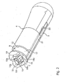
- Fig. 2 is a perspective view in a state of viewing up from a lower side of the same
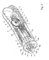
- Fig. 3 is a partially broken perspective view of the same
- Fig. 4 is a vertical sectional side view of the same
- Fig. 5 is a perspective view showing a half exposed state of a transfer head in starting to be used
- Fig. 6 is a vertical sectional side view of the same
- Fig. 7 is a perspective view showing a state of exposing a transfer head when used
- Fig. 8 is a vertical sectional side view of the same.
- the coating film transfer tool of the invention includes a first gear 3 mounted with a supply reel 2 and wound with a transfer tape T, a second gear 5 mounted with a take-up reel 4 for taking-up the transfer tape T after a transfer operation, a third gear 6 indirectly brought in meshing engagement with the first gear 3 and the second gear 5, and a tape reeling out means 7 as shown by Fig. 3 and Fig. 4 at a rear portion of the inside of a case main body 1 having a cylindrical shape and formed of a synthetic resin, which includes a transfer head support member 8 and a head cap 9 at a front portion of the inside of the case main body 1.
- the case main body 1 has an opening 10 at a front end thereof and is provided with a support shaft 11 of the first gear 3 mounted with the supply reel 2, a support shaft 12 of the second gear 5 mounted with the take-up reel 4, a support shaft 13 of the third gear 6 indirectly brought in mesh engagement with the first gear 3 and the second gear 5 at an inner side wall of a rear portion thereof.
- the transfer head support member 8 is held by a front portion at the inside of the case main body 1, and is provided with a transfer head 15 attached to a tape guide member 14 at a front end thereof.
- the transfer head 15 is projected from the opening 10 at the front end of the case main body 1, and rotatably carries the transfer roller 16 at a front end thereof.
- a barrel portion 17 of the head cap 9 having a cylindrical shape and formed of a synthetic resin is slidably fitted to a front portion at the inside of the case main body 1.
- An outer periphery of a front end of the barrel portion 17 is formed with a ring-like projection 18 projected to an outer side, in which left and right sides of the ring-like projection 18 are formed with a pair of left and right protecting members 19, 19 projected to a front side in a converging tapering shape.
- the protecting member 19 has upper and lower end edges 19a, 19b, at least the lower end edge 19b which comes into contact with a paper face P (refer to Fig. 4) constituting a face on which a transfer is bulged into a circular arc shape.
- the head cap 9 is urged to project to the front side from the front end opening 10 of the case main body 1 by a coil spring 20 provided at a rear side of the barrel portion 17 at a front portion of the inside of the case main body 1, and is maintained at an advanced position in a state of covering two left and right side faces of the transfer head 15 by the two left and right protecting members 19, 19 at a front end thereof when not used.
- the tape reeling out means 7 includes an operating rod 21 moved in cooperation with a movement in the front and rear directions of the barrel portion 17 of the head cap 9, a rack 22 moved in cooperation with a movement in the front and rear directions of the operating rod 21, a pinion 23 meshing with the rack 22, and a long hole 24 making the pinion 23 movable in front and rear directions and bringing the pinion 23 into a position so as to be able to be brought in mesh engagement with the first gear 3 mounted with the supply reel 2 and so as to separate the pinion 23 from the first gear 3.
- the pinion 23 is brought in mesh with the rack 22 at an advanced position of the head cap 9 when not used and is made movable to be able to be brought in mesh with the first gear 3 mounted with the supply reel 2 by moving the rack 22 in moving back the head cap 9 when started to be used as shown by Fig. 6.
- the pinion 23 rotates the supply reel 2 by being brought in mesh with the first gear 3 in accordance with moving back the head cap 9 in starting to be used shown in Fig. 6 to reel out the transfer tape T wound around the supply reel 2 by a desired length in accordance with the amount of rotating the pinion 23.
- the pinion 23 is detached from the rack 22 to be able to be idled, and after having been detached from the rack 22, guided by the long hole 24, the pinion 23 can be detached from the first gear 3 to an original position at which the pinion 23 was disposed when the head cap 9 was disposed at the advanced position.
- the pinion 23 is brought in mesh with the rack 22 and the first gear 3 when the head cap 9 is moved to the rear position and is brought in mesh with the first gear 3 when the head cap 9 is moved to the advanced position.
- the transfer tape T is wound around the take-up roller 4 from the supply reel 2 by way of a first guide pin 25, the transfer roller 16 of the transfer head 15 and a second guide pin 26.
- the head cap 9 when not used, the head cap 9 is urged to project to a front side from the front end opening 10 of the case main body 1 by the coil spring 20 contained at the rear side of the barrel portion 17 at the front portion of inside of the case main body 1, and is maintained at the advanced position in a state of covering the two left and right side faces of the transfer head 15 by the left and right protecting members 19, 19.
- the pinion 23 of the tape reeling out means 7 is moved to the rear side in cooperation with the rack 22 moved back by way of the operating rod 21 by moving back the head cap 9, brought in mesh with the first gear 3 and is rotated by further moving back the rack 22 to rotate the first gear 3.
- the transfer tape T wound around the supply reel 2 is automatically reeled out by a length in accordance with an amount of rotating by the pinion 23 and is supplied onto the transfer roll 16 of the transfer head 15.
- the transfer tape T holding the coating film can be disposed on the transfer roll 16, and coating film detachment can be prevented.
- the transfer tape T after having been transcribed is reeled by the take-up roller 4 rotated in synchronism with the first gear 3 by way of the third gear 6 and the second gear 5, and the pinion 23 detached from the rack 22 is separated from the first gear 3 by its own weight and is returned to the original position at which the pinion 23 was disposed when the head cap 9 was disposed at the advanced position.
- the pinion 23 may be made able to be returned to the original position by an urge force of a spring or the like.
Landscapes
- Adhesive Tape Dispensing Devices (AREA)
- Decoration By Transfer Pictures (AREA)
- Replacement Of Web Rolls (AREA)
Applications Claiming Priority (1)
| Application Number | Priority Date | Filing Date | Title |
|---|---|---|---|
| JP2006268899A JP2008087257A (ja) | 2006-09-29 | 2006-09-29 | 塗膜転写具 |
Publications (1)
| Publication Number | Publication Date |
|---|---|
| EP1905716A2 true EP1905716A2 (fr) | 2008-04-02 |
Family
ID=38776234
Family Applications (1)
| Application Number | Title | Priority Date | Filing Date |
|---|---|---|---|
| EP07015022A Withdrawn EP1905716A2 (fr) | 2006-09-29 | 2007-07-31 | Outil de transfert de film de revêtement |
Country Status (8)
| Country | Link |
|---|---|
| US (1) | US7766066B2 (fr) |
| EP (1) | EP1905716A2 (fr) |
| JP (1) | JP2008087257A (fr) |
| KR (1) | KR20080030436A (fr) |
| CN (1) | CN100493926C (fr) |
| AU (1) | AU2007207885A1 (fr) |
| SG (1) | SG141374A1 (fr) |
| TW (1) | TW200815213A (fr) |
Cited By (1)
| Publication number | Priority date | Publication date | Assignee | Title |
|---|---|---|---|---|
| GB2456416A (en) * | 2008-01-18 | 2009-07-22 | Plus Stationery Corp | Coating film transfer tool |
Families Citing this family (11)
| Publication number | Priority date | Publication date | Assignee | Title |
|---|---|---|---|---|
| US20090229763A1 (en) * | 2008-03-11 | 2009-09-17 | Nien-Chun Lin | Correction device having receiving and replacement functions |
| JP5011558B2 (ja) * | 2008-10-02 | 2012-08-29 | コクヨ株式会社 | 転写具 |
| US8397784B2 (en) | 2010-08-31 | 2013-03-19 | Sanford, L.P. | Correction tape dispenser with variable clutch mechanism |
| US8746313B2 (en) | 2010-12-29 | 2014-06-10 | Sanford, L.P. | Correction tape re-tensioning mechanism and correction tape dispenser comprising same |
| US8578999B2 (en) | 2010-12-29 | 2013-11-12 | Sanford, L.P. | Variable clutch mechanism and correction tape dispenser with variable clutch mechanism |
| US8746316B2 (en) | 2011-12-30 | 2014-06-10 | Sanford, L.P. | Variable clutch mechanism and correction tape dispenser with variable clutch mechanism |
| CN102745005B (zh) * | 2012-07-26 | 2015-01-21 | 富联(厦门)办公用品有限公司 | 一种薄膜涂抹装置 |
| JP6153484B2 (ja) * | 2014-02-24 | 2017-06-28 | オリンパス株式会社 | ワイヤ駆動装置およびマニピュレータ |
| JP6321537B2 (ja) * | 2014-12-26 | 2018-05-09 | 株式会社トンボ鉛筆 | 塗膜転写具 |
| JP6916508B2 (ja) * | 2016-11-15 | 2021-08-11 | プラス株式会社 | 塗膜転写具 |
| CN112848764A (zh) * | 2021-03-18 | 2021-05-28 | 黄福源 | 一种修正带及带体 |
Family Cites Families (4)
| Publication number | Priority date | Publication date | Assignee | Title |
|---|---|---|---|---|
| JP4603738B2 (ja) * | 2001-09-28 | 2010-12-22 | プラス株式会社 | 塗布膜転写具 |
| JP3909681B2 (ja) * | 2002-05-02 | 2007-04-25 | 株式会社トンボ鉛筆 | 塗膜転写具 |
| JP2004268322A (ja) | 2003-03-06 | 2004-09-30 | Tombow Pencil Co Ltd | 塗膜転写具 |
| EP1820762A1 (fr) * | 2006-02-17 | 2007-08-22 | 3L-Ludvigsen A/S | Dispositif de transfert de matériau comportant un capot de protection |
-
2006
- 2006-09-29 JP JP2006268899A patent/JP2008087257A/ja active Pending
- 2006-12-04 TW TW095144978A patent/TW200815213A/zh unknown
- 2006-12-15 KR KR1020060128505A patent/KR20080030436A/ko not_active Withdrawn
-
2007
- 2007-03-15 CN CNB200710086776XA patent/CN100493926C/zh not_active Expired - Fee Related
- 2007-07-31 EP EP07015022A patent/EP1905716A2/fr not_active Withdrawn
- 2007-08-16 AU AU2007207885A patent/AU2007207885A1/en not_active Abandoned
- 2007-08-29 US US11/897,213 patent/US7766066B2/en not_active Expired - Fee Related
- 2007-09-19 SG SG200708481-7A patent/SG141374A1/en unknown
Cited By (2)
| Publication number | Priority date | Publication date | Assignee | Title |
|---|---|---|---|---|
| GB2456416A (en) * | 2008-01-18 | 2009-07-22 | Plus Stationery Corp | Coating film transfer tool |
| GB2456416B (en) * | 2008-01-18 | 2012-07-18 | Plus Stationery Corp | Coating film transfer tool |
Also Published As
| Publication number | Publication date |
|---|---|
| KR20080030436A (ko) | 2008-04-04 |
| JP2008087257A (ja) | 2008-04-17 |
| US7766066B2 (en) | 2010-08-03 |
| CN101152816A (zh) | 2008-04-02 |
| CN100493926C (zh) | 2009-06-03 |
| TW200815213A (en) | 2008-04-01 |
| HK1115355A1 (zh) | 2008-11-28 |
| US20080078323A1 (en) | 2008-04-03 |
| AU2007207885A1 (en) | 2008-04-17 |
| SG141374A1 (en) | 2008-04-28 |
Similar Documents
| Publication | Publication Date | Title |
|---|---|---|
| US7766066B2 (en) | Coating film transfer tool | |
| EP1908716A2 (fr) | Outil de transfert de film de revêtement | |
| EP1982844B1 (fr) | Outil de transfert de revetement | |
| JP4617430B2 (ja) | 塗膜転写具 | |
| JPH092724A (ja) | 塗布膜転写具及び塗布膜転写具における転写テープ詰替方法 | |
| JP7341802B2 (ja) | テープカッター | |
| JP2008279719A (ja) | 塗膜転写具 | |
| JP2010083086A (ja) | テープ繰出し装置 | |
| EP3312020B1 (fr) | Outil de transfert de film de revêtement | |
| JP4461675B2 (ja) | 転写具の転写ヘッド部構造および転写具 | |
| JP3712723B2 (ja) | 転写テープ式修正具 | |
| JP2008001456A (ja) | 粘着テープディスペンサ | |
| JP7330496B2 (ja) | 塗膜転写具 | |
| HK1115355B (en) | Coating film transfer tool | |
| JP4005130B2 (ja) | テープディスペンサ | |
| JP6395964B1 (ja) | ローラー型清掃具 | |
| JP2012081672A (ja) | 塗膜転写具 | |
| JPH07247041A (ja) | ロールテープ、テープ端末接続装置及びテープ端末接続方法 | |
| JP2025088200A (ja) | テープ貼付具 | |
| CN116061595A (zh) | 转印用具 | |
| JP2004148837A (ja) | 塗布膜転写具 | |
| JPS6330263B2 (fr) | ||
| JPH0728146U (ja) | 字消し具 | |
| JPH0541894U (ja) | テープ式字消し器 | |
| JP2009119835A (ja) | ダンピングヘッドを備えた塗膜転写具。 |
Legal Events
| Date | Code | Title | Description |
|---|---|---|---|
| PUAI | Public reference made under article 153(3) epc to a published international application that has entered the european phase |
Free format text: ORIGINAL CODE: 0009012 |
|
| AK | Designated contracting states |
Kind code of ref document: A2 Designated state(s): AT BE BG CH CY CZ DE DK EE ES FI FR GB GR HU IE IS IT LI LT LU LV MC MT NL PL PT RO SE SI SK TR |
|
| AX | Request for extension of the european patent |
Extension state: AL BA HR MK YU |
|
| STAA | Information on the status of an ep patent application or granted ep patent |
Free format text: STATUS: THE APPLICATION IS DEEMED TO BE WITHDRAWN |
|
| 18D | Application deemed to be withdrawn |
Effective date: 20100201 |