EP1905860A2 - Revêtement poreux et abradable et procédé de fabrication - Google Patents
Revêtement poreux et abradable et procédé de fabrication Download PDFInfo
- Publication number
- EP1905860A2 EP1905860A2 EP07117320A EP07117320A EP1905860A2 EP 1905860 A2 EP1905860 A2 EP 1905860A2 EP 07117320 A EP07117320 A EP 07117320A EP 07117320 A EP07117320 A EP 07117320A EP 1905860 A2 EP1905860 A2 EP 1905860A2
- Authority
- EP
- European Patent Office
- Prior art keywords
- abradable
- layer
- powder
- patterned
- applying
- Prior art date
- Legal status (The legal status is an assumption and is not a legal conclusion. Google has not performed a legal analysis and makes no representation as to the accuracy of the status listed.)
- Withdrawn
Links
Images


Classifications
-
- C—CHEMISTRY; METALLURGY
- C23—COATING METALLIC MATERIAL; COATING MATERIAL WITH METALLIC MATERIAL; CHEMICAL SURFACE TREATMENT; DIFFUSION TREATMENT OF METALLIC MATERIAL; COATING BY VACUUM EVAPORATION, BY SPUTTERING, BY ION IMPLANTATION OR BY CHEMICAL VAPOUR DEPOSITION, IN GENERAL; INHIBITING CORROSION OF METALLIC MATERIAL OR INCRUSTATION IN GENERAL
- C23C—COATING METALLIC MATERIAL; COATING MATERIAL WITH METALLIC MATERIAL; SURFACE TREATMENT OF METALLIC MATERIAL BY DIFFUSION INTO THE SURFACE, BY CHEMICAL CONVERSION OR SUBSTITUTION; COATING BY VACUUM EVAPORATION, BY SPUTTERING, BY ION IMPLANTATION OR BY CHEMICAL VAPOUR DEPOSITION, IN GENERAL
- C23C4/00—Coating by spraying the coating material in the molten state, e.g. by flame, plasma or electric discharge
- C23C4/02—Pretreatment of the material to be coated, e.g. for coating on selected surface areas
-
- C—CHEMISTRY; METALLURGY
- C23—COATING METALLIC MATERIAL; COATING MATERIAL WITH METALLIC MATERIAL; CHEMICAL SURFACE TREATMENT; DIFFUSION TREATMENT OF METALLIC MATERIAL; COATING BY VACUUM EVAPORATION, BY SPUTTERING, BY ION IMPLANTATION OR BY CHEMICAL VAPOUR DEPOSITION, IN GENERAL; INHIBITING CORROSION OF METALLIC MATERIAL OR INCRUSTATION IN GENERAL
- C23C—COATING METALLIC MATERIAL; COATING MATERIAL WITH METALLIC MATERIAL; SURFACE TREATMENT OF METALLIC MATERIAL BY DIFFUSION INTO THE SURFACE, BY CHEMICAL CONVERSION OR SUBSTITUTION; COATING BY VACUUM EVAPORATION, BY SPUTTERING, BY ION IMPLANTATION OR BY CHEMICAL VAPOUR DEPOSITION, IN GENERAL
- C23C4/00—Coating by spraying the coating material in the molten state, e.g. by flame, plasma or electric discharge
- C23C4/01—Selective coating, e.g. pattern coating, without pre-treatment of the material to be coated
Definitions
- the disclosure relates generally to abradable coatings, and more specifically to porous abradable coatings applied to a substrate.
- Abradable type coatings have been applied to the turbine shroud to help establish a minimum, i.e., optimum, running clearance between the shroud and bucket tips under steady-state temperature conditions.
- coatings have been applied to the surface of the shroud facing the buckets using a material that can be readily abraded by the tips of the buckets as they turn inside the shroud at high speed with little or no damage to the bucket tips. Initially, a clearance exists between the bucket tips and the coating when the gas turbine is stopped and the components are at ambient temperature.
- abradable coatings are effective clearance minimizers, a coating that, as a whole, could better withstand local rubs (i.e. withstand a local rub on the coating without wholesale or large area delamination of the coating) would be desirable. This can be achieved via increased coating porosity.
- coating porosity is achieved by including a polymeric component in the coating, the polymeric component being burned out after coating application, leaving behind a porosity. A more efficient and effective means of creating porosity in a abradable coating is desirable.
- a porous abradable coating including at least one abradable layer applicable to a substrate, said at least one abradable layer comprising coarsely cut powder pieces.
- Also disclosed is a method for applying a porous abradable coating including selecting a coarsely cut abradable powder comprising coarsely cut powder pieces, applying at least one abradable layer comprising the coarsely cut abradable powder to a substrate, and creating a porosity in the at least one layer via the coarsely cut abradable powder.
- a method for applying a porous abradable coating including selecting a coarsely cut abradable powder comprising coarsely cut powder pieces, applying an adhesion abradable layer comprising the coarsely cut powder to a substrate, applying a patterned abradable layer including the coarsely cut abradable powder to the adhesion abradable layer, adhering the patterned abradable layer to the adhesion abradable layer, the adhering being promoted via a roughness of the coarsely cut abradable powder, and creating a porosity in the adhesion layer and the patterned layer via the coarsely cut abradable powder pieces.
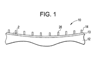
- a porous abradable coating 10 is illustrated.
- the coating 10 is applied to a substrate 12, such as an environmental barrier coated (EBC) turbine shroud, in at least one layer.
- the coating 10 is applied in an adhesion abradable layer 13 and a patterned abradable layer 14.
- a method for applying the coating 10 will be discussed hereinbelow, beginning with selection of the powder 15 (as shown in Figure 2) comprising the coating 10.
- the powder 15 is selected to include relatively large, coarse cut pieces 16.
- the selection process involves a sifting of the abradable powder 15 through a screen that includes square openings approximately 90 microns across. The powder 15 that passes through these openings is then sifted through a screen that includes square openings approximately 44 microns across. The powder 15 that passes through these openings is then discarded, and the powder 15 that cannot pass is selected. Thus, pieces 16 with an approximate diameter between 44 and 90 microns are used.
- other more conventional powders 15 use a finer powder that includes pieces as small as 8 (ceramic) and 16 (metal) microns.
- the largeness and coarseness of the pieces 16 allows the powder 15 applied in the layers 14 and 13 to include relatively large open voids 18.
- these voids 18 allow for a relatively large coating porosity 20 of at least 8 percent volume (with an exemplary range of 8-12%), even after a heat treatment that will be discussed later in the disclosure.
- the coarseness of the pieces 16 produce a degree of roughness 22 in the adhesion layer 13 that promotes adhesion to the patterned layer 14.
- the powder 15 includes a ceramic composition, which may specifically comprise yttria stabilized zirconia, barium strontium aluminosilicate, and a composition including .75 mole BaO, .25 mole SrO, 1 mole Al203, and 2 moles Si02.
- the coating 10 may be applied.
- the adhesion layer 13 (partially applied in the Figure) is applied or "flash-coated" to the substrate 12 via a thermal spray process, such as air plasma spray 24 or physical vapor deposition (PVD).
- parameter of the air plasma spray is calibrated and optimized for coarse particles that include sizes selected to collectively produce the desired level of porosity.
- the patterned layer 14 is applied to the adhesion layer 13, with a pattern of ridges 26 being formed in the patterned layer 14 (partially applied in the Figure) by, in an exemplary embodiment, successive passes of plasma sprayed powder 15 over a pattern mask 28, with parameter of the air plasma spray again being optimized for coarse particles that include sizes selected to collectively produce the desired level of porosity. As mentioned above, adherence of patterned layer 14 is promoted and strengthened via the roughness 22 of the adhesion layer 13.
- the layers 13 and 14 are heat-treated.
- this heat treatment is accomplished via an air furnace, though a plasma torch may also be used.
- the heat is applied at a temperature sufficient enough to partially melt the pieces 16, so as to mechanically and chemically bond each piece 16 to an adjacent piece 16 (and in so doing, strengthen the bond between the layers 13 and 14), aiding in erosion resistance during turbine operation.
- the temperature is not so great however (between 1250 and 1300 degrees C), as to completely melt the pieces 16 and decrease porosity by causing the voids 18 to fill with the melting pieces 16.
- the combination of moderate heat treatment and particle sizing maintain an incomplete melting, which further maintains the voids 18 between the only semi-molten pieces 16. As nothing has to be completely burned out of the coating 10 to create the desired porosity 20, the integrity of the pieces 16 is substantially preserved, and thus, the desired porosity 20 is efficiently and effectively created.
Landscapes
- Chemical & Material Sciences (AREA)
- Engineering & Computer Science (AREA)
- Mechanical Engineering (AREA)
- Plasma & Fusion (AREA)
- Chemical Kinetics & Catalysis (AREA)
- Materials Engineering (AREA)
- Physics & Mathematics (AREA)
- Metallurgy (AREA)
- Organic Chemistry (AREA)
- Coating By Spraying Or Casting (AREA)
- Turbine Rotor Nozzle Sealing (AREA)
- Materials For Medical Uses (AREA)
- Application Of Or Painting With Fluid Materials (AREA)
Applications Claiming Priority (1)
| Application Number | Priority Date | Filing Date | Title |
|---|---|---|---|
| US11/537,238 US20080081109A1 (en) | 2006-09-29 | 2006-09-29 | Porous abradable coating and method for applying the same |
Publications (2)
| Publication Number | Publication Date |
|---|---|
| EP1905860A2 true EP1905860A2 (fr) | 2008-04-02 |
| EP1905860A3 EP1905860A3 (fr) | 2009-04-08 |
Family
ID=38691830
Family Applications (1)
| Application Number | Title | Priority Date | Filing Date |
|---|---|---|---|
| EP07117320A Withdrawn EP1905860A3 (fr) | 2006-09-29 | 2007-09-27 | Revêtement poreux et abradable et procédé de fabrication |
Country Status (4)
| Country | Link |
|---|---|
| US (1) | US20080081109A1 (fr) |
| EP (1) | EP1905860A3 (fr) |
| JP (1) | JP5219442B2 (fr) |
| CN (1) | CN101161733A (fr) |
Cited By (4)
| Publication number | Priority date | Publication date | Assignee | Title |
|---|---|---|---|---|
| US10273192B2 (en) | 2015-02-17 | 2019-04-30 | Rolls-Royce Corporation | Patterned abradable coating and methods for the manufacture thereof |
| US11313243B2 (en) | 2018-07-12 | 2022-04-26 | Rolls-Royce North American Technologies, Inc. | Non-continuous abradable coatings |
| US11976569B2 (en) | 2019-11-14 | 2024-05-07 | Rolls-Royce Corporation | Fused filament fabrication of abradable coatings |
| US12459196B2 (en) | 2019-11-14 | 2025-11-04 | Rolls-Royce Corporation | Patterned filament for fused filament fabrication |
Families Citing this family (15)
| Publication number | Priority date | Publication date | Assignee | Title |
|---|---|---|---|---|
| US8047773B2 (en) * | 2007-08-23 | 2011-11-01 | General Electric Company | Gas turbine shroud support apparatus |
| US8046915B2 (en) * | 2007-12-12 | 2011-11-01 | General Electric Company | Methods for making composite containment casings |
| EP2075416B1 (fr) * | 2007-12-27 | 2011-05-18 | Techspace Aero | Procédé de fabrication d'un élément de turbomachine et dispositif ainsi obtenu |
| FR2994397B1 (fr) * | 2012-08-07 | 2014-08-01 | Snecma | Revetement en materiau abradable a faible rugosite de surface |
| US20150118444A1 (en) * | 2013-10-31 | 2015-04-30 | General Electric Company | Methods of manufacturing silica-forming articles having engineered surfaces to enhance resistance to creep sliding under high-temperature loading |
| JP6240779B2 (ja) | 2013-12-12 | 2017-11-29 | ゼネラル・エレクトリック・カンパニイ | ポリマーゲル下でアブレイダブル皮膜を堆積する方法 |
| CN103805987B (zh) * | 2014-01-23 | 2016-08-17 | 南京纳创新材料技术有限公司 | 一种图案化钛涂层硬组织替代材料的制备方法 |
| US20150354392A1 (en) * | 2014-06-10 | 2015-12-10 | General Electric Company | Abradable coatings |
| US20160084102A1 (en) * | 2014-09-18 | 2016-03-24 | General Electric Company | Abradable seal and method for forming an abradable seal |
| CN104451672B (zh) * | 2014-12-18 | 2017-03-15 | 上海交通大学 | 一种调控热障涂层界面形貌的激光粉末沉积方法 |
| CN104451671A (zh) * | 2014-12-18 | 2015-03-25 | 上海交通大学 | 一种涡轮热端部件热障涂层的激光加工方法 |
| EP3040441A1 (fr) * | 2014-12-31 | 2016-07-06 | General Electric Company | Revêtements abradables de carénage et procédés de fabrication |
| US20160305319A1 (en) * | 2015-04-17 | 2016-10-20 | General Electric Company | Variable coating porosity to influence shroud and rotor durability |
| FR3037511B1 (fr) * | 2015-06-18 | 2017-06-02 | Snecma | Dispositif de revetement d'un carter annulaire de turbomachine |
| US11781437B2 (en) * | 2021-05-04 | 2023-10-10 | General Electric Company | Cold spray duct for a gas turbine engine |
Family Cites Families (14)
| Publication number | Priority date | Publication date | Assignee | Title |
|---|---|---|---|---|
| US4450184A (en) * | 1982-02-16 | 1984-05-22 | Metco Incorporated | Hollow sphere ceramic particles for abradable coatings |
| ATE41455T1 (de) * | 1985-04-30 | 1989-04-15 | Yamauchi Corp | Presswalze fuer papiermaschinen. |
| US4936745A (en) * | 1988-12-16 | 1990-06-26 | United Technologies Corporation | Thin abradable ceramic air seal |
| US5305726A (en) * | 1992-09-30 | 1994-04-26 | United Technologies Corporation | Ceramic composite coating material |
| US5419971A (en) * | 1993-03-03 | 1995-05-30 | General Electric Company | Enhanced thermal barrier coating system |
| US6733907B2 (en) * | 1998-03-27 | 2004-05-11 | Siemens Westinghouse Power Corporation | Hybrid ceramic material composed of insulating and structural ceramic layers |
| US6537021B2 (en) * | 2001-06-06 | 2003-03-25 | Chromalloy Gas Turbine Corporation | Abradeable seal system |
| AU2003207560A1 (en) * | 2002-01-14 | 2003-07-30 | Sulzer Metco (Us) Inc. | High temperature spray dried composite abradable powder for combustion spraying and abradable barrier coating produced using same |
| US20050003172A1 (en) * | 2002-12-17 | 2005-01-06 | General Electric Company | 7FAstage 1 abradable coatings and method for making same |
| US6887528B2 (en) * | 2002-12-17 | 2005-05-03 | General Electric Company | High temperature abradable coatings |
| PL1548144T3 (pl) * | 2003-12-17 | 2010-07-30 | Sulzer Metco Us Inc | Maszyna przepływowa z ceramiczną warstwą ścieralną |
| ES2340037T3 (es) * | 2003-12-17 | 2010-05-28 | Sulzer Metco (Us) Inc. | Turbo maquina con capa ceramica de abrasion.. |
| US7614847B2 (en) * | 2004-11-24 | 2009-11-10 | General Electric Company | Pattern for the surface of a turbine shroud |
| US7600968B2 (en) * | 2004-11-24 | 2009-10-13 | General Electric Company | Pattern for the surface of a turbine shroud |
-
2006
- 2006-09-29 US US11/537,238 patent/US20080081109A1/en not_active Abandoned
-
2007
- 2007-09-27 EP EP07117320A patent/EP1905860A3/fr not_active Withdrawn
- 2007-09-27 JP JP2007250618A patent/JP5219442B2/ja not_active Expired - Fee Related
- 2007-09-29 CN CNA2007101532585A patent/CN101161733A/zh active Pending
Cited By (4)
| Publication number | Priority date | Publication date | Assignee | Title |
|---|---|---|---|---|
| US10273192B2 (en) | 2015-02-17 | 2019-04-30 | Rolls-Royce Corporation | Patterned abradable coating and methods for the manufacture thereof |
| US11313243B2 (en) | 2018-07-12 | 2022-04-26 | Rolls-Royce North American Technologies, Inc. | Non-continuous abradable coatings |
| US11976569B2 (en) | 2019-11-14 | 2024-05-07 | Rolls-Royce Corporation | Fused filament fabrication of abradable coatings |
| US12459196B2 (en) | 2019-11-14 | 2025-11-04 | Rolls-Royce Corporation | Patterned filament for fused filament fabrication |
Also Published As
| Publication number | Publication date |
|---|---|
| US20080081109A1 (en) | 2008-04-03 |
| JP2008088554A (ja) | 2008-04-17 |
| EP1905860A3 (fr) | 2009-04-08 |
| JP5219442B2 (ja) | 2013-06-26 |
| CN101161733A (zh) | 2008-04-16 |
Similar Documents
| Publication | Publication Date | Title |
|---|---|---|
| EP1905860A2 (fr) | Revêtement poreux et abradable et procédé de fabrication | |
| EP2050931B1 (fr) | Systèmes et procédés impliquant des joints abradables étanches à l'air | |
| US9598973B2 (en) | Seal systems for use in turbomachines and methods of fabricating the same | |
| US6887528B2 (en) | High temperature abradable coatings | |
| JP6538323B2 (ja) | タービンシュラウドの表面パターンの3d印刷法 | |
| CN105443165B (zh) | 可磨耗密封件及用于形成可磨耗密封件的方法 | |
| JP2006036632A (ja) | 7FA+e第1段アブレイダブル被膜及びその作製方法 | |
| US9551058B2 (en) | Coating methods and a coated substrate | |
| EP3055445B1 (fr) | Revêtement en alliage d'aluminium dotés d'inhibiteurs de corrosion de type terres rares et métaux de transition | |
| US9644489B1 (en) | Additive manufacturing of abradable mesh structure on ring segment surface | |
| Dorfman et al. | Gas turbines use ‘abradable’coatings for clearance-control seals | |
| US7749565B2 (en) | Method for applying and dimensioning an abradable coating | |
| EP3037570B1 (fr) | Procédé de formation d'un revêtement d'étanchéité | |
| US6884470B2 (en) | Application method for abradable material | |
| JP6313762B2 (ja) | 低表面粗度を有する材料からなる摩耗性コーティング | |
| CN111356820B (zh) | 具有自适应冷却开口的带涂层的部件及其制备方法 | |
| EP3502422A1 (fr) | Joint abrasable de compresseur présentant une meilleure rétention de lubrifiant solide | |
| EP3754045A1 (fr) | Revêtement de protection thermique, élément de turbine, turbine à gaz et procédé de fabrication de revêtement de protection thermique | |
| CN110662884B (zh) | 具有凹槽尖端和致密的氧化物弥散强化层的涡轮机叶片 | |
| Sporer et al. | Ceramics for abradable shroud seal applications | |
| US20060275553A1 (en) | Electrically conductive thermal barrier coatings capable for use in electrode discharge machining | |
| EP3626850B1 (fr) | Couche de collage pour revêtement céramique résistant aux spallations | |
| JP6193987B2 (ja) | タービンハードウェアに断熱コーティングを選択的に生成するための処理 | |
| US6702553B1 (en) | Abradable material for clearance control | |
| CN104514583A (zh) | 陶瓷基体复合材料部件、涡轮机系统和制造方法 |
Legal Events
| Date | Code | Title | Description |
|---|---|---|---|
| PUAI | Public reference made under article 153(3) epc to a published international application that has entered the european phase |
Free format text: ORIGINAL CODE: 0009012 |
|
| AK | Designated contracting states |
Kind code of ref document: A2 Designated state(s): AT BE BG CH CY CZ DE DK EE ES FI FR GB GR HU IE IS IT LI LT LU LV MC MT NL PL PT RO SE SI SK TR |
|
| AX | Request for extension of the european patent |
Extension state: AL BA HR MK YU |
|
| PUAL | Search report despatched |
Free format text: ORIGINAL CODE: 0009013 |
|
| AK | Designated contracting states |
Kind code of ref document: A3 Designated state(s): AT BE BG CH CY CZ DE DK EE ES FI FR GB GR HU IE IS IT LI LT LU LV MC MT NL PL PT RO SE SI SK TR |
|
| AX | Request for extension of the european patent |
Extension state: AL BA HR MK RS |
|
| 17P | Request for examination filed |
Effective date: 20091008 |
|
| AKX | Designation fees paid |
Designated state(s): AT BE BG CH CY CZ DE DK EE ES FI FR GB GR HU IE IS IT LI LT LU LV MC MT NL PL PT RO SE SI SK TR |
|
| 17Q | First examination report despatched |
Effective date: 20100211 |
|
| STAA | Information on the status of an ep patent application or granted ep patent |
Free format text: STATUS: THE APPLICATION IS DEEMED TO BE WITHDRAWN |
|
| 18D | Application deemed to be withdrawn |
Effective date: 20131017 |