EP1905909A2 - Vorrichtung zum festen Zusammenfügen von Fertigträgern und Fertigpfeilern - Google Patents
Vorrichtung zum festen Zusammenfügen von Fertigträgern und Fertigpfeilern Download PDFInfo
- Publication number
- EP1905909A2 EP1905909A2 EP07116594A EP07116594A EP1905909A2 EP 1905909 A2 EP1905909 A2 EP 1905909A2 EP 07116594 A EP07116594 A EP 07116594A EP 07116594 A EP07116594 A EP 07116594A EP 1905909 A2 EP1905909 A2 EP 1905909A2
- Authority
- EP
- European Patent Office
- Prior art keywords
- pillars
- beams
- metal
- insert
- inserts
- Prior art date
- Legal status (The legal status is an assumption and is not a legal conclusion. Google has not performed a legal analysis and makes no representation as to the accuracy of the status listed.)
- Granted
Links
- 239000002184 metal Substances 0.000 claims abstract description 43
- 229910052751 metal Inorganic materials 0.000 claims abstract description 43
- 239000011150 reinforced concrete Substances 0.000 claims abstract description 8
- 238000009417 prefabrication Methods 0.000 claims abstract description 6
- 238000010276 construction Methods 0.000 claims abstract description 3
- 230000002787 reinforcement Effects 0.000 claims description 22
- 238000004873 anchoring Methods 0.000 claims description 15
- 235000000396 iron Nutrition 0.000 claims description 15
- 230000003014 reinforcing effect Effects 0.000 claims description 13
- 238000005266 casting Methods 0.000 claims description 6
- 239000011083 cement mortar Substances 0.000 claims description 5
- 230000000284 resting effect Effects 0.000 claims description 5
- 239000004570 mortar (masonry) Substances 0.000 claims description 4
- 239000004568 cement Substances 0.000 claims description 2
- 238000009738 saturating Methods 0.000 claims description 2
- 230000000903 blocking effect Effects 0.000 claims 1
- 239000002131 composite material Substances 0.000 claims 1
- 238000009434 installation Methods 0.000 description 3
- XEEYBQQBJWHFJM-UHFFFAOYSA-N Iron Chemical compound [Fe] XEEYBQQBJWHFJM-UHFFFAOYSA-N 0.000 description 2
- 210000001503 joint Anatomy 0.000 description 2
- 238000005336 cracking Methods 0.000 description 1
- 230000001419 dependent effect Effects 0.000 description 1
- 230000002452 interceptive effect Effects 0.000 description 1
- 229910052742 iron Inorganic materials 0.000 description 1
- 238000010008 shearing Methods 0.000 description 1
Images


Classifications
-
- E—FIXED CONSTRUCTIONS
- E04—BUILDING
- E04B—GENERAL BUILDING CONSTRUCTIONS; WALLS, e.g. PARTITIONS; ROOFS; FLOORS; CEILINGS; INSULATION OR OTHER PROTECTION OF BUILDINGS
- E04B1/00—Constructions in general; Structures which are not restricted either to walls, e.g. partitions, or floors or ceilings or roofs
- E04B1/18—Structures comprising elongated load-supporting parts, e.g. columns, girders, skeletons
- E04B1/20—Structures comprising elongated load-supporting parts, e.g. columns, girders, skeletons the supporting parts consisting of concrete, e.g. reinforced concrete, or other stonelike material
- E04B1/21—Connections specially adapted therefor
- E04B1/215—Connections specially adapted therefor comprising metallic plates or parts
-
- E—FIXED CONSTRUCTIONS
- E04—BUILDING
- E04C—STRUCTURAL ELEMENTS; BUILDING MATERIALS
- E04C5/00—Reinforcing elements, e.g. for concrete; Auxiliary elements therefor
- E04C5/16—Auxiliary parts for reinforcements, e.g. connectors, spacers, stirrups
Definitions
- the invention falls within the sector of multi-level framework building structures which are suitable for multi-functional use and are intended to withstand major overloads, including those of seismic origin, said structures being formed by prefabricated pillars made of - usually vibrated and precompressed - reinforced concrete and provided in the zones where they are connected to the beams, also made of ordinary or precompressed reinforced concrete, with corbels which then receive, resting on them, the ends of the said beams which finally support the sides of prefabricated honeycomb panels which are also made of reinforced concrete, for forming the floors.
- the invention intends to overcome the limitations of the prior art with an apparatus according to Claim 1 and the subsequent dependent claims, which facilitates the correct arrangement in position of the beams on the support corbels of single-piece pillars of predefined height, owing to the presence of teeth and engaging seats on the mutually co-operating metal inserts of the two prefabricated components, which prevent undesirable movements of these components.
- a further object of the invention consists in facilitating the arrangement in position of supplementary reinforcement irons which secure the horizontal and vertical connections of the beams to the pillars and in improving the results achieved with these connections, so as to obtain connection characteristics similar to those which are obtained in a multi-level framework building structure constructed on-site.
- pillars, beams and floor sills are self-supporting and their installation does not require the temporary use of bracing members.
- these components simply rest on each other. After positioning the necessary supplementary reinforcements and after performing on-site a supplementary casting, the said components are rigidly secured to each other.
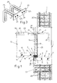
- the prefabricated side pillars 1 and the middle pillars 1' are single-piece and of predefined height for forming a framework with a predetermined number of levels and that, in the region of the floor sill of each level, the said pillars are provided integrally with laterally projecting parts which are arranged on one side, as indicated by 101 in Figure 1, in the case of the side pillars 1, whereas they are situated on both sides opposite each other, as indicated by 101' in Figure 2, in the case of the middle pillars 1' and form actual corbels reinforced by the special internal reinforcements 201 of the pillars which have a greater number of brackets in the linear direction close to the joint which comprises these corbels.
- each corbel 101, 101' thereof receives, embedded therein, a metal insert A, as shown in Figure 5, which comprises a robust angle-piece 2 of suitable dimensions, which forms mainly the upper side and consecutive front side of the corbel 101, 101' and which has, welded internally and perpendicularly to its flanges, the ends of anchoring plates 3 which are positioned edgewise and are inserted to a considerable depth inside the body of the pillar 1,1' and which have intermediate holes 4 passed through by corresponding reinforcing irons 5 able to interact with the reinforcing irons of the said pillar so as to keep the aforementioned parts 2 and 3 firmly in position.
- the anchoring plates 3 have an asymmetrical position with respect to the angle-piece 2 so that it is possible to use, in the corbels 101' of the middle pillars 1', inserts A with identical characteristics which, with the angle-pieces 2 in the centred position, carry the anchoring plates 3 arranged alongside each other, with the holes 4 mutually aligned, so as to be able to be anchored in the pillar with common reinforcing irons 5.
- the insert A is completed by at least one pair of vertical holes 6 with a symmetrical arrangement on the top flange of the angle-piece 2, at a short distance from the sides of this angle-piece, which allow access with tie-rods described further below to the inner threaded part of metal bushes 7 welded underneath the said upper flange of the angle-piece 2.
- a tooth 8 formed for example by a square metal block of suitable dimensions and described more fully below is longitudinally welded in the space between the said holes 6, on the visible side of the upper flange of the angle-piece 2.
- a metal insert B which comprises a robust plate 9 which is able to form mainly the bottom side of the bottom end corner zone of the beam 10, which is visible and which has, welded longitudinally and at a short distance from its visible front edge, a tooth 11 formed for example also by a square metal block and having for example the same height as the block which forms the tooth 8 of the aforementioned insert A and which at the bottom is coplanar with the bottom side of the beam 10, such that, with respect to this side, the said plate 9 is suitably raised.
- the plate 9 is anchored firmly to the beam 10 by means of a pair of anchoring plates 12, at one end of which the said plate is welded, these plates 12 being positioned edgewise and being provided with intermediate holes 13 passed through by reinforcing irons 14 which interact suitably with the internal reinforcement of the beam 10.
- the ends of the plate 9 have, welded thereto, the bottom ends of metal tubular members 15 of equal height, for example with a rectangular cross-section, which with their bottom end project from the plate 9 so as to touch the ideal horizontal plane which contains the visible bottom side of the tooth 11 and the inner wall of this projecting bottom section of the tubes 15 is open as indicated by 16 in Figure 9, so as to establish a connection between the internal cavity of the said tubes and the chamber 17 which is situated underneath the plate 9 and which is defined, as well as by this plate, by the bottom section of the tubes 15, by the tooth 11 and, parallel to the latter, by a folded sheet-metal wall 18 welded at least to the bottom side of the plate 9.
- the wall 18 has the same height as the tooth 11.
- the tubes 15 have an interaxial distance substantially the same as that of the upper holes 6 in the insert A of the pillars.
- the tooth 8 of the insert A of the corbels engages inside the aforementioned chamber 17 of the insert B of the beams and rests on the plate 9, while the tooth 11 of this plate rests on the upper flange of the angle-piece 2 of the insert A and this flange closes at the bottom the said chamber 17.
- the holes 6 in the insert A are situated inside the bottom end of the tubes 15.
- the beams 10 are anchored mechanically to the corbels 101, 101' of the pillars and are prevented from performing undesirable horizontal movements, so as to allow rapid and correct mounting of the prefabricated beams on the pillars 1, 1' which are fixed on-site, without the use of reinforcements or bracing members.
- the tubes 15 receive, inserted in them, the threaded tie-rods 19 which, with one end, are screwed into the bushes 7 of the insert A and which, with the opposite - also threaded - end, project conveniently from the said tubes 15 into which a self-levelling, high-strength, expanding cement mortar 20 is subsequently injected, said mortar filling completely these tubes and saturating also the chamber 17 with the engaging teeth 8 and 11, thereby improving the strength of the joint and helping preserve over time all the metal components which form it, since they are completely embedded in the cement.
- the mortar manages to withstand extremely high loads, which are substantially twice those which are usual for this type of product, since it is confined within a box-shaped structure of the metal system for supporting the beam, enabling the apparatus to absorb lower horizontal forces which allow it to counteract effectively the reverse moments which may occur during seismic events, providing a rigid and hyperstatic joint.
- the tubes 15 are closed at the top by inserts 21 or with the holed end of reinforcing plates extending partly over the outer side of the beam 10 and then the said inserts 21 are fixed to the top end of the tie-rods 19 with nuts 22 and/or other suitable means.
- the middle pillars 1' may have embedded therein, instead of the insert C according to Figure 3, oppositely arranged inserts C' as can be seen in Figure 4, said inserts comprising internally threaded bushes 125' for being able to screw in there the threaded bars 26 which co-operate with the upper reinforcements 110 of the beams 10, these bushes 125' being able to be connected to the reinforcements of the pillar by means of special anchoring irons 25'.
- joint C which is very much simpler (see Figure 2) whereby the said joint is formed by corrugated sheet-metal tubes which are embedded transversely in the middle pillars so as to form therein through-holes inside which it is possible to secure, using expanding cement mortar and/or other suitable means, reinforcing bars 26 which project by equal amounts into the beams resting on the opposite corbels 101' of a same middle pillar 1'.
- the strength of the beam-pillar connecting joint has to be increased, after checking that the pillar and beam are able to withstand the respective shearing and flexing stresses, steps are taken to increase proportionally the number of bushes and upper bars in the fixture along the outer side and the size of the teeth 8, 11 formed by the square opposition blocks on the supports of the inner side, all of which can be easily deduced also by means tests.
- the plate 9 of the insert B of the beams may be replaced with an angle-piece so as to form also a frontal protection for the said beams, which is particularly useful for preventing damage thereto during transportation and arrangement in position.
Landscapes
- Engineering & Computer Science (AREA)
- Architecture (AREA)
- Civil Engineering (AREA)
- Structural Engineering (AREA)
- Physics & Mathematics (AREA)
- Electromagnetism (AREA)
- Joining Of Building Structures In Genera (AREA)
- Buildings Adapted To Withstand Abnormal External Influences (AREA)
- Rod-Shaped Construction Members (AREA)
- Conveying And Assembling Of Building Elements In Situ (AREA)
Applications Claiming Priority (1)
| Application Number | Priority Date | Filing Date | Title |
|---|---|---|---|
| IT000649A ITBO20060649A1 (it) | 2006-09-21 | 2006-09-21 | Apparato per l'ancoraggio rigido tra travi prefabbricate portasolaio e pilastri prefabbricati, nelle costruzioni edilizie con intelaiatura pluripiano ed in cemento armato. |
Publications (3)
| Publication Number | Publication Date |
|---|---|
| EP1905909A2 true EP1905909A2 (de) | 2008-04-02 |
| EP1905909A3 EP1905909A3 (de) | 2008-04-09 |
| EP1905909B1 EP1905909B1 (de) | 2011-05-11 |
Family
ID=39025365
Family Applications (1)
| Application Number | Title | Priority Date | Filing Date |
|---|---|---|---|
| EP07116594A Not-in-force EP1905909B1 (de) | 2006-09-21 | 2007-09-17 | Vorrichtung zum festen Zusammenfügen von Fertigträgern und Fertigpfeilern |
Country Status (3)
| Country | Link |
|---|---|
| EP (1) | EP1905909B1 (de) |
| AT (1) | ATE509166T1 (de) |
| IT (1) | ITBO20060649A1 (de) |
Cited By (9)
| Publication number | Priority date | Publication date | Assignee | Title |
|---|---|---|---|---|
| WO2008116448A3 (de) * | 2007-03-23 | 2009-06-25 | Frank Gmbh & Co Kg Max | Stahlbetonkonstruktion für ein gebäude |
| CN102080353A (zh) * | 2010-12-13 | 2011-06-01 | 中铁大桥局集团有限公司 | 一种可拆装式牛腿及其安装方法 |
| ITRM20110632A1 (it) * | 2011-11-29 | 2013-05-30 | Buildesign S R L | Trave strutturale perfezionata, sistema strutturale utilizzante tale trave perfezionata e metodo di realizzazione. |
| WO2014043826A1 (es) * | 2012-09-21 | 2014-03-27 | Soluciones Integrales De Reducción De Vibraciones | Sistema y método de conexión viga-columna |
| CN110468967A (zh) * | 2019-08-14 | 2019-11-19 | 中国建筑一局(集团)有限公司 | 超大超重预制外挂板与主体结构梁的连接节点及施工方法 |
| CN110565799A (zh) * | 2019-08-30 | 2019-12-13 | 浙江中清大建筑产业化有限公司 | 一种用于防震的装配式混凝土梁柱连接方法 |
| US10794053B2 (en) * | 2016-10-17 | 2020-10-06 | South China University Of Technology | Reinforced compound concrete beam-column joint containing demolished concrete lumps and a construction method |
| CN111764505A (zh) * | 2020-06-28 | 2020-10-13 | 湖北省建工第二建设有限公司 | 混凝土预制梁与现浇柱的连接结构及其施工方法 |
| CN116950260A (zh) * | 2023-07-19 | 2023-10-27 | 江苏科技大学 | 一种钢结构体系及预制装配方法 |
Families Citing this family (1)
| Publication number | Priority date | Publication date | Assignee | Title |
|---|---|---|---|---|
| IT202100010508A1 (it) * | 2021-04-26 | 2022-10-26 | Geoplast Spa | Sistema di elementi modulari per la realizzazione di solai nervati sopraelevati e/o aerati |
Citations (2)
| Publication number | Priority date | Publication date | Assignee | Title |
|---|---|---|---|---|
| EP0398812A1 (de) | 1989-05-19 | 1990-11-22 | Logicia | Verbindung eines waagerechten Trägers mit einer senkrechten Stütze |
| FR2756305A1 (fr) | 1996-11-22 | 1998-05-29 | Knauf | Plancher en beton a entrevous legers et resistants |
Family Cites Families (2)
| Publication number | Priority date | Publication date | Assignee | Title |
|---|---|---|---|---|
| GB1039126A (en) * | 1963-11-21 | 1966-08-17 | John Laing Res And Dev Ltd | Improvements in joints between structural members |
| DE19952594B4 (de) * | 1999-11-02 | 2008-11-27 | Halfen Gmbh | Auflager für ein Stahlbeton-Fertigbauteil |
-
2006
- 2006-09-21 IT IT000649A patent/ITBO20060649A1/it unknown
-
2007
- 2007-09-17 AT AT07116594T patent/ATE509166T1/de not_active IP Right Cessation
- 2007-09-17 EP EP07116594A patent/EP1905909B1/de not_active Not-in-force
Patent Citations (2)
| Publication number | Priority date | Publication date | Assignee | Title |
|---|---|---|---|---|
| EP0398812A1 (de) | 1989-05-19 | 1990-11-22 | Logicia | Verbindung eines waagerechten Trägers mit einer senkrechten Stütze |
| FR2756305A1 (fr) | 1996-11-22 | 1998-05-29 | Knauf | Plancher en beton a entrevous legers et resistants |
Cited By (14)
| Publication number | Priority date | Publication date | Assignee | Title |
|---|---|---|---|---|
| WO2008116448A3 (de) * | 2007-03-23 | 2009-06-25 | Frank Gmbh & Co Kg Max | Stahlbetonkonstruktion für ein gebäude |
| CN102080353A (zh) * | 2010-12-13 | 2011-06-01 | 中铁大桥局集团有限公司 | 一种可拆装式牛腿及其安装方法 |
| CN102080353B (zh) * | 2010-12-13 | 2012-09-05 | 中铁大桥局集团有限公司 | 一种可拆装式牛腿及其安装方法 |
| RU2623374C2 (ru) * | 2011-11-29 | 2017-06-26 | Л.Е.Р. С.Р.Л. | Усовершенствованная конструкционная балка, строительная система, использующая указанную усовершенствованную балку, и способ конструирования |
| WO2013080235A3 (en) * | 2011-11-29 | 2013-07-25 | Buildesign S.R.L. | A wooden constructural beam having hook like anchor elements and construction method |
| ITRM20110632A1 (it) * | 2011-11-29 | 2013-05-30 | Buildesign S R L | Trave strutturale perfezionata, sistema strutturale utilizzante tale trave perfezionata e metodo di realizzazione. |
| RU2623374C9 (ru) * | 2011-11-29 | 2017-09-22 | Л.Е.Р. С.Р.Л. | Усовершенствованная конструкционная балка, строительная система, использующая указанную усовершенствованную балку, и способ конструирования |
| WO2014043826A1 (es) * | 2012-09-21 | 2014-03-27 | Soluciones Integrales De Reducción De Vibraciones | Sistema y método de conexión viga-columna |
| US10794053B2 (en) * | 2016-10-17 | 2020-10-06 | South China University Of Technology | Reinforced compound concrete beam-column joint containing demolished concrete lumps and a construction method |
| CN110468967A (zh) * | 2019-08-14 | 2019-11-19 | 中国建筑一局(集团)有限公司 | 超大超重预制外挂板与主体结构梁的连接节点及施工方法 |
| CN110468967B (zh) * | 2019-08-14 | 2024-02-09 | 中国建筑一局(集团)有限公司 | 超大超重预制外挂板与主体结构梁的连接节点及施工方法 |
| CN110565799A (zh) * | 2019-08-30 | 2019-12-13 | 浙江中清大建筑产业化有限公司 | 一种用于防震的装配式混凝土梁柱连接方法 |
| CN111764505A (zh) * | 2020-06-28 | 2020-10-13 | 湖北省建工第二建设有限公司 | 混凝土预制梁与现浇柱的连接结构及其施工方法 |
| CN116950260A (zh) * | 2023-07-19 | 2023-10-27 | 江苏科技大学 | 一种钢结构体系及预制装配方法 |
Also Published As
| Publication number | Publication date |
|---|---|
| EP1905909B1 (de) | 2011-05-11 |
| ITBO20060649A1 (it) | 2008-03-22 |
| ATE509166T1 (de) | 2011-05-15 |
| EP1905909A3 (de) | 2008-04-09 |
Similar Documents
| Publication | Publication Date | Title |
|---|---|---|
| EP1905909B1 (de) | Vorrichtung zum festen Zusammenfügen von Fertigträgern und Fertigpfeilern | |
| KR101253519B1 (ko) | 콘크리트 충전 강관기둥을 이용한 기존 건축물의 내진보강 공법 | |
| TWI438326B (zh) | Semi - pre - cast flooring and its board construction method | |
| KR101107300B1 (ko) | 강판전단벽 | |
| JP6788981B2 (ja) | 鋼製部材の接合構造 | |
| EP3383607B1 (de) | Schalung zur bereitstellung eines betonfundamentelements, insbesondere ein sockel mit exponierten horizontalen, bewehrungsstäben, sockel mit dieser schalung und struktur mit dieser sockelleiste | |
| CN113026993B (zh) | 一种装配式组合连接梁窗洞构件、结构及制作施工方法 | |
| KR101617221B1 (ko) | 내진 보강형 증축 리모델링 모듈러유닛의 접합구조 및 접합방법 | |
| JP7670753B2 (ja) | 梁の構造、梁主筋配筋用の支持部材、および梁主筋の配筋方法 | |
| KR20180058962A (ko) | 철근콘크리트 프레임 내진 보강 구조 | |
| JP2010159543A (ja) | 耐震補強構造 | |
| KR20190036248A (ko) | 현장타설 내벽결합 내진보강 구조 및 이를 이용한 내진보강 방법 | |
| JP3690437B2 (ja) | 既存建築物の耐震補強構造 | |
| JP2009046829A (ja) | 耐震補強壁 | |
| JP5144182B2 (ja) | 既存建物の耐震補強構造並びに耐震補強方法 | |
| JP2009155870A (ja) | 補強構造 | |
| JP4904382B2 (ja) | 既存建築物の耐震補強方法及び耐震補強構造 | |
| JP2002357009A (ja) | 制振梁及び制振梁の構築方法 | |
| KR100626326B1 (ko) | 콘크리트 구조물 | |
| KR102321433B1 (ko) | 건물 외부 장착 방식의 내진 보강 구조체 | |
| JP2017014713A (ja) | 既存コンクリート構造物補強構造 | |
| KR101797960B1 (ko) | 중립축 상승부재를 갖는 강재보 및 이를 이용한 합성보 | |
| KR102205718B1 (ko) | 내진 보강을 위한 부축벽 조립체 | |
| KR100605363B1 (ko) | 스틸스터드 패널 | |
| KR101139762B1 (ko) | 건축물용 보강 벽의 시공 방법 |
Legal Events
| Date | Code | Title | Description |
|---|---|---|---|
| PUAI | Public reference made under article 153(3) epc to a published international application that has entered the european phase |
Free format text: ORIGINAL CODE: 0009012 |
|
| PUAL | Search report despatched |
Free format text: ORIGINAL CODE: 0009013 |
|
| AK | Designated contracting states |
Kind code of ref document: A2 Designated state(s): AT BE BG CH CY CZ DE DK EE ES FI FR GB GR HU IE IS IT LI LT LU LV MC MT NL PL PT RO SE SI SK TR |
|
| AX | Request for extension of the european patent |
Extension state: AL BA HR MK YU |
|
| AK | Designated contracting states |
Kind code of ref document: A3 Designated state(s): AT BE BG CH CY CZ DE DK EE ES FI FR GB GR HU IE IS IT LI LT LU LV MC MT NL PL PT RO SE SI SK TR |
|
| AX | Request for extension of the european patent |
Extension state: AL BA HR MK RS |
|
| 17P | Request for examination filed |
Effective date: 20080617 |
|
| 17Q | First examination report despatched |
Effective date: 20080717 |
|
| AKX | Designation fees paid |
Designated state(s): AT BE BG CH CY CZ DE DK EE ES FI FR GB GR HU IE IS IT LI LT LU LV MC MT NL PL PT RO SE SI SK TR |
|
| GRAP | Despatch of communication of intention to grant a patent |
Free format text: ORIGINAL CODE: EPIDOSNIGR1 |
|
| GRAS | Grant fee paid |
Free format text: ORIGINAL CODE: EPIDOSNIGR3 |
|
| GRAA | (expected) grant |
Free format text: ORIGINAL CODE: 0009210 |
|
| AK | Designated contracting states |
Kind code of ref document: B1 Designated state(s): AT BE BG CH CY CZ DE DK EE ES FI FR GB GR HU IE IS IT LI LT LU LV MC MT NL PL PT RO SE SI SK TR |
|
| REG | Reference to a national code |
Ref country code: GB Ref legal event code: FG4D |
|
| REG | Reference to a national code |
Ref country code: CH Ref legal event code: EP |
|
| REG | Reference to a national code |
Ref country code: IE Ref legal event code: FG4D |
|
| REG | Reference to a national code |
Ref country code: DE Ref legal event code: R096 Ref document number: 602007014449 Country of ref document: DE Effective date: 20110622 |
|
| REG | Reference to a national code |
Ref country code: NL Ref legal event code: VDEP Effective date: 20110511 |
|
| PG25 | Lapsed in a contracting state [announced via postgrant information from national office to epo] |
Ref country code: PT Free format text: LAPSE BECAUSE OF FAILURE TO SUBMIT A TRANSLATION OF THE DESCRIPTION OR TO PAY THE FEE WITHIN THE PRESCRIBED TIME-LIMIT Effective date: 20110912 Ref country code: SE Free format text: LAPSE BECAUSE OF FAILURE TO SUBMIT A TRANSLATION OF THE DESCRIPTION OR TO PAY THE FEE WITHIN THE PRESCRIBED TIME-LIMIT Effective date: 20110511 Ref country code: LT Free format text: LAPSE BECAUSE OF FAILURE TO SUBMIT A TRANSLATION OF THE DESCRIPTION OR TO PAY THE FEE WITHIN THE PRESCRIBED TIME-LIMIT Effective date: 20110511 |
|
| PG25 | Lapsed in a contracting state [announced via postgrant information from national office to epo] |
Ref country code: AT Free format text: LAPSE BECAUSE OF FAILURE TO SUBMIT A TRANSLATION OF THE DESCRIPTION OR TO PAY THE FEE WITHIN THE PRESCRIBED TIME-LIMIT Effective date: 20110511 Ref country code: IS Free format text: LAPSE BECAUSE OF FAILURE TO SUBMIT A TRANSLATION OF THE DESCRIPTION OR TO PAY THE FEE WITHIN THE PRESCRIBED TIME-LIMIT Effective date: 20110911 Ref country code: FI Free format text: LAPSE BECAUSE OF FAILURE TO SUBMIT A TRANSLATION OF THE DESCRIPTION OR TO PAY THE FEE WITHIN THE PRESCRIBED TIME-LIMIT Effective date: 20110511 Ref country code: ES Free format text: LAPSE BECAUSE OF FAILURE TO SUBMIT A TRANSLATION OF THE DESCRIPTION OR TO PAY THE FEE WITHIN THE PRESCRIBED TIME-LIMIT Effective date: 20110822 Ref country code: GR Free format text: LAPSE BECAUSE OF FAILURE TO SUBMIT A TRANSLATION OF THE DESCRIPTION OR TO PAY THE FEE WITHIN THE PRESCRIBED TIME-LIMIT Effective date: 20110812 Ref country code: CY Free format text: LAPSE BECAUSE OF FAILURE TO SUBMIT A TRANSLATION OF THE DESCRIPTION OR TO PAY THE FEE WITHIN THE PRESCRIBED TIME-LIMIT Effective date: 20110511 Ref country code: SI Free format text: LAPSE BECAUSE OF FAILURE TO SUBMIT A TRANSLATION OF THE DESCRIPTION OR TO PAY THE FEE WITHIN THE PRESCRIBED TIME-LIMIT Effective date: 20110511 Ref country code: BE Free format text: LAPSE BECAUSE OF FAILURE TO SUBMIT A TRANSLATION OF THE DESCRIPTION OR TO PAY THE FEE WITHIN THE PRESCRIBED TIME-LIMIT Effective date: 20110511 Ref country code: LV Free format text: LAPSE BECAUSE OF FAILURE TO SUBMIT A TRANSLATION OF THE DESCRIPTION OR TO PAY THE FEE WITHIN THE PRESCRIBED TIME-LIMIT Effective date: 20110511 |
|
| PG25 | Lapsed in a contracting state [announced via postgrant information from national office to epo] |
Ref country code: NL Free format text: LAPSE BECAUSE OF FAILURE TO SUBMIT A TRANSLATION OF THE DESCRIPTION OR TO PAY THE FEE WITHIN THE PRESCRIBED TIME-LIMIT Effective date: 20110511 |
|
| PG25 | Lapsed in a contracting state [announced via postgrant information from national office to epo] |
Ref country code: EE Free format text: LAPSE BECAUSE OF FAILURE TO SUBMIT A TRANSLATION OF THE DESCRIPTION OR TO PAY THE FEE WITHIN THE PRESCRIBED TIME-LIMIT Effective date: 20110511 Ref country code: CZ Free format text: LAPSE BECAUSE OF FAILURE TO SUBMIT A TRANSLATION OF THE DESCRIPTION OR TO PAY THE FEE WITHIN THE PRESCRIBED TIME-LIMIT Effective date: 20110511 |
|
| PG25 | Lapsed in a contracting state [announced via postgrant information from national office to epo] |
Ref country code: SK Free format text: LAPSE BECAUSE OF FAILURE TO SUBMIT A TRANSLATION OF THE DESCRIPTION OR TO PAY THE FEE WITHIN THE PRESCRIBED TIME-LIMIT Effective date: 20110511 Ref country code: PL Free format text: LAPSE BECAUSE OF FAILURE TO SUBMIT A TRANSLATION OF THE DESCRIPTION OR TO PAY THE FEE WITHIN THE PRESCRIBED TIME-LIMIT Effective date: 20110511 Ref country code: RO Free format text: LAPSE BECAUSE OF FAILURE TO SUBMIT A TRANSLATION OF THE DESCRIPTION OR TO PAY THE FEE WITHIN THE PRESCRIBED TIME-LIMIT Effective date: 20110511 Ref country code: DK Free format text: LAPSE BECAUSE OF FAILURE TO SUBMIT A TRANSLATION OF THE DESCRIPTION OR TO PAY THE FEE WITHIN THE PRESCRIBED TIME-LIMIT Effective date: 20110511 |
|
| PLBE | No opposition filed within time limit |
Free format text: ORIGINAL CODE: 0009261 |
|
| STAA | Information on the status of an ep patent application or granted ep patent |
Free format text: STATUS: NO OPPOSITION FILED WITHIN TIME LIMIT |
|
| 26N | No opposition filed |
Effective date: 20120214 |
|
| PG25 | Lapsed in a contracting state [announced via postgrant information from national office to epo] |
Ref country code: MC Free format text: LAPSE BECAUSE OF NON-PAYMENT OF DUE FEES Effective date: 20110930 |
|
| REG | Reference to a national code |
Ref country code: CH Ref legal event code: PL |
|
| GBPC | Gb: european patent ceased through non-payment of renewal fee |
Effective date: 20110917 |
|
| REG | Reference to a national code |
Ref country code: DE Ref legal event code: R097 Ref document number: 602007014449 Country of ref document: DE Effective date: 20120214 |
|
| REG | Reference to a national code |
Ref country code: IE Ref legal event code: MM4A |
|
| REG | Reference to a national code |
Ref country code: FR Ref legal event code: ST Effective date: 20120531 |
|
| REG | Reference to a national code |
Ref country code: DE Ref legal event code: R119 Ref document number: 602007014449 Country of ref document: DE Effective date: 20120403 |
|
| PG25 | Lapsed in a contracting state [announced via postgrant information from national office to epo] |
Ref country code: IE Free format text: LAPSE BECAUSE OF NON-PAYMENT OF DUE FEES Effective date: 20110917 Ref country code: LI Free format text: LAPSE BECAUSE OF NON-PAYMENT OF DUE FEES Effective date: 20110930 Ref country code: DE Free format text: LAPSE BECAUSE OF NON-PAYMENT OF DUE FEES Effective date: 20120403 Ref country code: CH Free format text: LAPSE BECAUSE OF NON-PAYMENT OF DUE FEES Effective date: 20110930 |
|
| PG25 | Lapsed in a contracting state [announced via postgrant information from national office to epo] |
Ref country code: GB Free format text: LAPSE BECAUSE OF NON-PAYMENT OF DUE FEES Effective date: 20110917 Ref country code: FR Free format text: LAPSE BECAUSE OF NON-PAYMENT OF DUE FEES Effective date: 20110930 |
|
| PG25 | Lapsed in a contracting state [announced via postgrant information from national office to epo] |
Ref country code: MT Free format text: LAPSE BECAUSE OF FAILURE TO SUBMIT A TRANSLATION OF THE DESCRIPTION OR TO PAY THE FEE WITHIN THE PRESCRIBED TIME-LIMIT Effective date: 20110511 |
|
| PG25 | Lapsed in a contracting state [announced via postgrant information from national office to epo] |
Ref country code: LU Free format text: LAPSE BECAUSE OF NON-PAYMENT OF DUE FEES Effective date: 20110917 |
|
| PG25 | Lapsed in a contracting state [announced via postgrant information from national office to epo] |
Ref country code: BG Free format text: LAPSE BECAUSE OF FAILURE TO SUBMIT A TRANSLATION OF THE DESCRIPTION OR TO PAY THE FEE WITHIN THE PRESCRIBED TIME-LIMIT Effective date: 20110811 |
|
| PG25 | Lapsed in a contracting state [announced via postgrant information from national office to epo] |
Ref country code: TR Free format text: LAPSE BECAUSE OF FAILURE TO SUBMIT A TRANSLATION OF THE DESCRIPTION OR TO PAY THE FEE WITHIN THE PRESCRIBED TIME-LIMIT Effective date: 20110511 |
|
| PG25 | Lapsed in a contracting state [announced via postgrant information from national office to epo] |
Ref country code: HU Free format text: LAPSE BECAUSE OF FAILURE TO SUBMIT A TRANSLATION OF THE DESCRIPTION OR TO PAY THE FEE WITHIN THE PRESCRIBED TIME-LIMIT Effective date: 20110511 |
|
| PGFP | Annual fee paid to national office [announced via postgrant information from national office to epo] |
Ref country code: IT Payment date: 20140926 Year of fee payment: 8 |
|
| PG25 | Lapsed in a contracting state [announced via postgrant information from national office to epo] |
Ref country code: IT Free format text: LAPSE BECAUSE OF NON-PAYMENT OF DUE FEES Effective date: 20150917 |