EP1905936B1 - Joint d'angle pour cadres de porte et fenêtre - Google Patents
Joint d'angle pour cadres de porte et fenêtre Download PDFInfo
- Publication number
- EP1905936B1 EP1905936B1 EP06425639A EP06425639A EP1905936B1 EP 1905936 B1 EP1905936 B1 EP 1905936B1 EP 06425639 A EP06425639 A EP 06425639A EP 06425639 A EP06425639 A EP 06425639A EP 1905936 B1 EP1905936 B1 EP 1905936B1
- Authority
- EP
- European Patent Office
- Prior art keywords
- sections
- door
- pin
- corner joint
- joining
- Prior art date
- Legal status (The legal status is an assumption and is not a legal conclusion. Google has not performed a legal analysis and makes no representation as to the accuracy of the status listed.)
- Not-in-force
Links
- 238000000465 moulding Methods 0.000 claims description 4
- 239000000463 material Substances 0.000 claims description 3
- 238000007789 sealing Methods 0.000 description 4
- 238000005253 cladding Methods 0.000 description 3
- 239000004411 aluminium Substances 0.000 description 2
- 229910052782 aluminium Inorganic materials 0.000 description 2
- XAGFODPZIPBFFR-UHFFFAOYSA-N aluminium Chemical compound [Al] XAGFODPZIPBFFR-UHFFFAOYSA-N 0.000 description 2
- 230000037431 insertion Effects 0.000 description 2
- 238000003780 insertion Methods 0.000 description 2
- 238000004519 manufacturing process Methods 0.000 description 2
- 239000007787 solid Substances 0.000 description 2
- 238000006243 chemical reaction Methods 0.000 description 1
- 239000003795 chemical substances by application Substances 0.000 description 1
- 230000008878 coupling Effects 0.000 description 1
- 238000010168 coupling process Methods 0.000 description 1
- 238000005859 coupling reaction Methods 0.000 description 1
- 230000000694 effects Effects 0.000 description 1
- 230000001771 impaired effect Effects 0.000 description 1
- 230000008595 infiltration Effects 0.000 description 1
- 238000001764 infiltration Methods 0.000 description 1
- 230000007774 longterm Effects 0.000 description 1
- 230000013011 mating Effects 0.000 description 1
- 229910052751 metal Inorganic materials 0.000 description 1
- 239000002184 metal Substances 0.000 description 1
- 230000002093 peripheral effect Effects 0.000 description 1
- 229920003002 synthetic resin Polymers 0.000 description 1
- 239000000057 synthetic resin Substances 0.000 description 1
- XLYOFNOQVPJJNP-UHFFFAOYSA-N water Substances O XLYOFNOQVPJJNP-UHFFFAOYSA-N 0.000 description 1
Images




Classifications
-
- E—FIXED CONSTRUCTIONS
- E06—DOORS, WINDOWS, SHUTTERS, OR ROLLER BLINDS IN GENERAL; LADDERS
- E06B—FIXED OR MOVABLE CLOSURES FOR OPENINGS IN BUILDINGS, VEHICLES, FENCES OR LIKE ENCLOSURES IN GENERAL, e.g. DOORS, WINDOWS, BLINDS, GATES
- E06B3/00—Window sashes, door leaves, or like elements for closing wall or like openings; Layout of fixed or moving closures, e.g. windows in wall or like openings; Features of rigidly-mounted outer frames relating to the mounting of wing frames
- E06B3/96—Corner joints or edge joints for windows, doors, or the like frames or wings
- E06B3/9616—Corner joints or edge joints for windows, doors, or the like frames or wings characterised by the sealing at the junction of the frame members
- E06B3/962—Mitre joints
-
- E—FIXED CONSTRUCTIONS
- E06—DOORS, WINDOWS, SHUTTERS, OR ROLLER BLINDS IN GENERAL; LADDERS
- E06B—FIXED OR MOVABLE CLOSURES FOR OPENINGS IN BUILDINGS, VEHICLES, FENCES OR LIKE ENCLOSURES IN GENERAL, e.g. DOORS, WINDOWS, BLINDS, GATES
- E06B3/00—Window sashes, door leaves, or like elements for closing wall or like openings; Layout of fixed or moving closures, e.g. windows in wall or like openings; Features of rigidly-mounted outer frames relating to the mounting of wing frames
- E06B3/96—Corner joints or edge joints for windows, doors, or the like frames or wings
- E06B3/984—Corner joints or edge joints for windows, doors, or the like frames or wings specially adapted for frame members of wood or other material worked in a similar way
- E06B3/9845—Mitre joints
Definitions
- the present invention relates to a corner joint for sections of door and window frames.
- the joint in question is intended to be used mainly in the sector relating to the production of wooden door and window frames or accessories for door and window frames, in particular for rigidly fixing together two sections of a frame along the joining plane.
- the frame of a door or window which may or may not be associated with cladding mouldings made of metal or PVC, usually consists of several wooden sections the ends of which are fixed in pairs at the corners of the frame, by means of a corner joint provided with suitable connection means.
- the sections thus assembled in the form of a surrounding frame may form either a casement, intended to be inset in a brickwork wall, or a leaf of a door or a window and, in this latter case, usually delimit a glazed surface.
- connection means mentioned above may be, in accordance with the known art, of various types and for example envisage providing on the joining face of a first section several shaped projections alternating with recesses which are able to mate with corresponding recesses and projections provided on the joining face of the other section.
- the sections may be connected together at 90°, i.e. with a first section in contact laterally on the other one, or at 45°, i.e. with an inclined common face.
- connection means consisting of wedges or pins provided with widened portions, generally in the form of a dovetail, which can be inserted into seats formed on either side of the joining plane and provided with an undercut inside which the widened portions of the pins grip so as to retain rigidly together the two sections of the frame.
- the pins are inserted transversely with respect the plane defined by the surrounding window or door frame, while according to the teaching of FR 1,175,665 , the pins are inserted parallel to the plane of the surrounding window or door frame.
- the joining face may be provided with further coupling or centring elements usually consisting of cylindrical pins and corresponding seats formed in the opposite faces of the two frame parts to be joined together.
- a sealing device for timber window frame for sealing the joint between two frame sections connected at 90°.
- This device comprises a joint element displaced between the two sections, and fixing elements, with which the joint element can be fixed to the frame sections.
- These fixing elements are placed in holes arranged on the joint element, for example in the form of dowels.
- this sealing device does not consent to obtain a strong grip of the frame sections, because it cannot prevent them to translate along the direction parallel to the insertion axis of the dowels.
- Another drawback consists in the difficulty of centering the joint element on the frame sections and then inserting fixing elements.
- the object of the present invention is to eliminate the drawbacks of the prior art mentioned above, by providing a corner joint for sections of door and window frames, which ensures an optimum seal against atmospheric agents.
- Another object of the present invention is to provide a corner joint which is able to fix rigidly together the sections of a door or window frame.
- Another object of the present invention is to provide a corner joint which is operationally entirely effective and reliable.
- a further object of the present invention is to provide a corner joint which is simple and inexpensive to manufacture.
- a further object of the present invention is to provide a corner joint which is not aesthetically impaired by the presence of the line joining together the two faces of the sections of the door and window frames.
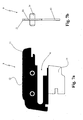
- 1 denotes overall the corner joint for sections of door and window frames according to the invention.
- This joint is intended for the assembly of wooden sections of any type and any shape in order to form wooden door and window frames suitable in particular for cladding with aluminium or PVC mouldings.
- the corner joint 1 comprises in a manner conventional per se a first and a second section, indicated by 2 and 3, which are usually joined together in accordance with the known art by means of fixing means 4 along the respective joining faces 2', 3' of the sections.
- the frame which is thus obtained usually has the form of a quadrangular surrounding frame formed by two uprights and two crosspieces which define a plane of lie.
- This plane is that in which the door or window frame is arranged and comprises an inner side and an outer side.
- the fixing means 4 comprise a pair of first openings 5, 6 which are formed in opposite positions on the two faces 2', 3' of the two sections 2, 3 so as to form a seat 7 which extends on either side of the joining plane of the sections and which is able to receive a pin 8 which is shaped so as to match the seat 7 and positioned so as to connect together the said sections 2, 3.
- the joint 1 also comprises a connection element 9 which is arranged between the two sections 2, 3 along the joining plane and has second openings 10 positioned opposite and as a continuation of the first openings 2, 3.
- the number of pairs of first openings 5, 6 (and corresponding second openings 10) and the type of fixing means 4 associated with the said first openings 5, 6 for fastening together the two sections 2, 3 may vary depending on the constructional requirements of the frame.
- fixing means 4 Some preferred embodiments of fixing means 4 will be described below.
- connection element 9 substantially consists of a plate which is preferably made of plastic material and which is shaped in the manner of the profile of the joining faces 2', 3', except for the area occupied by the second openings 10.
- connection element 9 has a first portion 11, which is preferably made of rigid plastic material, such as for example a high-strength ABS synthetic resin, having a perimetral edge 12 able to remain visible along an outer peripheral section thereof, once the frame is completely prepared and assembled.
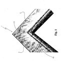
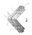
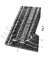
- the example according to Figures 1-3 relates to the frame of a leaf having a first side F1 ( Figure 2 ) intended to receive a cladding with aluminium sections, able to face the external environment, and a second side F2 ( Figure 1 ) intended to face the inside of the building.
- the edge 12 of the connection element will therefore in this case be advantageously visible in the side F2 of the frame.
- connection element has a second portion 13 which forms one piece with the first portion and is for example obtained by means of co-moulding and which is resiliently yielding under the compressive force exerted by the fixing means 4.
- the resilient reaction of this second portion allows the sealing effect between the two sections 2, 3 between which the element 9 is arranged to be increased.
- the first portion extends over the entire area of the connection element forming the support core on which the second portion is co-moulded.
- connection element 9 has, fixed thereon, two pairs of cylindrical pins 14 which project from its faces 15, 16 in opposite directions so as to be inserted with grip inside corresponding blind holes 17 formed in the faces of the two sections 2, 3.
- cylindrical is understood as meaning the shape of any solid form which has a side surface with parallel generatrix lines, even though not delimiting the cylinder commonly known as a straight cylinder.
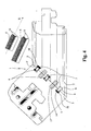
- each first opening 5, 6 is shaped in the manner of a groove, which extends in a direction X parallel to the joining face of the section 2, 3 from its outer perimeter and extends inside the said section 2, 3 from its face with a widened portion able to define an undercut 18.
- the seat 7 obtained from the grooves 5, 6 thus formed receives a correspondingly shaped pin 8 with solid flanges 19 which widen in the form of a wedge from the middle section so as to be gripped in the undercuts 18 of the grooves 5,6 and thus keep the sections 2, 3 joined together.
- the pins 8 are inserted in seats 7 which extend in directions X transverse to the plane of lie of the frame.
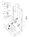
- the joint 1 according to the second example of embodiment shown in Figures 6 , 7a and 7b is provided with a single pin 8 which is inserted inside the seat 7 parallel to the plane of lie in a direction indicated by X'.
- insertion is performed from the outside of the frame towards the inside.
- the seats are blind and do not affect the side of the section opposite to the starting side from which they extend.
- the ends 8' and 8 " of the pin 8 are arranged inside transverse holes 20 formed in internally hollow and threaded cylindrical bushes 21 inserted inside channels 22 formed in the respective sections 2, 3.
- the said ends 8' and 8" of the pin 8 are provided with elongated eyelets 23 in the direction of extension of the pins 8. These eyelets 23 are situated at a relative distance from each other able to ensure that their engagement with suitable grub screws 24, screwed into the internal thread of the bushes 21, forces the pin 8 to move the two sections 2, 3 towards each other.
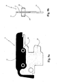
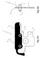
- the pin 8 has the form of a circular ring and is inserted inside annular grooves 5,6 formed by means coring on the joining faces of the sections and defining a pair of cylindrical shapes 25.
- the pin 8 is provided internally with a through-cavity 27 which tapers from the ends towards the middle section so as to define a double conicity.
- the abovementioned cavity 27 is passed through by a screw 28 and by a nut screw 29, which both have an elongated shape, which are inserted inside holes formed in the respective sections 2, 3 and which, mating with each other, force with the head 30 the pin 8 to expand its grip inside the seat 8, thereby mechanically retaining and fastening together the two sections 2, 3.
- the invention thus conceived therefore achieves the predefined objects.
Landscapes
- Engineering & Computer Science (AREA)
- Civil Engineering (AREA)
- Structural Engineering (AREA)
- Joining Of Corner Units Of Frames Or Wings (AREA)
Claims (8)
- jonction angulaire (1) pour profilés de menuiseries, comportant:- un premier (2) et un second (3) profilé pouvant être jointés entre eux pour la formation d'un cadre, à niveau de leurs faces de raccordement respectives (2', 3') séparées par un plan de jonction, et reliées par des moyens de fixation (4), qui prévoient que sur les faces de raccordement (2', 3') susdites soient obtenues dans des positions opposées des premières ouvertures (5, 6) aptes à réaliser un siège (7) qui se développe à cheval sur le plan de jonction, et lesquels incluent au moins une goupille (8) susceptible de s'engager dans le siège (7) susdit pour fixer les profilés (2, 3) susdits entre eux;- au moins un élément de raccordement (9) interposé entre les premier (2) et second (3) profilés susdits, à niveau du plan de jonction susdit, muni d'au moins une première portion (11) avec son bord à vue (12) depuis une face (F2) du cadre susdit ;caractérisée en ce que
chaque première ouverture (5, 6) susdite est façonnée en forme de rainure s'étendant le long d'un sens (X) parallèle par rapport à la face de raccordement (2' , 3') à partir de son périmètre extérieur et se développant à l'intérieur du profilé (2, 3) susdit avec au moins une portion élargie apte à définir au moins une contre-dépouille (18) ; le siège (7) susdit obtenu des rainures des faces opposées (2', 3') étant apte à abriter la goupille (8) susdite contre-façonnée par rapport au siège (7) susdit susceptible de raccorder les profilés (2, 3) susdits, en ayant prise par ses ailes élargies (19) sur les contre-dépouilles (18) des rainures susdites ;
et que l'élément de raccordement (9) susdit :- est une plaque munie de secondes ouvertures (10) positionnées à niveau des premières ouvertures opposées (5, 6) susdites raccordant les premières ouvertures opposées (5, 6) susdites et façonnée selon le profilé des faces de raccordement (2', 3'), à l'exception de la zone occupée par les secondes ouvertures (10) ;- et comporte au moins deux goupilles cylindriques (14) saillant de ses faces (15, 16) dans des sens opposés susceptibles de s'introduire par prise mécanique à l'intérieur de trous borgnes homologues (17) obtenus dans les faces de raccordement (2', 3') des deux profilés (2, 3) dans une position correspondant aux goupilles cylindriques (14). - jonction angulaire (1) pour profilés de menuiseries selon la revendication 1, caractérisée en ce que l'élément de raccordement (9) susdit est muni d'au moins une seconde portion élastiquement mouvante (13) susceptible d'être comprimée dans la jonction pour améliorer la tenue des profilés (2, 3) susdits.
- jonction angulaire (1) pour profilés de menuiseries selon la revendication 2, caractérisée en ce que l'élément de raccordement (9) susdit est formé en matière plastique par co-estampage des deux portions (11, 13) susdites, dont la première (11) étant plus rigide que la seconde (13).
- jonction angulaire (1) pour profilés de menuiseries selon la revendication 1, caractérisée en ce que la goupille (8) susdite est introduite transversalement par rapport au sol de la taille du cadre susdit.
- jonction angulaire (1) pour profilés de menuiseries selon la revendication 1, caractérisée en ce que la goupille (8) susdite est introduite parallèlement par rapport au sol de la taille du cadre susdit.
- jonction angulaire pour profilés de menuiseries selon la revendication 1, caractérisée en ce que la goupille (8) susdite est intérieurement munie d'une cavité passante (27) avec au moins une conicité, la cavité (27) susdite étant traversée par une vis (28) et par une vis femelle (29) introduites dans des trous obtenus de leurs profilés respectifs (2, 3), lesquelles, par leur emmanchement, forcent la goupille (8) susdite en prise sur le siège (7) susdit.
- jonction angulaire (1) pour profilés de menuiseries selon la revendication 1, caractérisée en ce que les extrémités (8', 8") de la goupille (8) susdite sont agencées à l'intérieur de trous transversaux (20) de buses (21) introduites dans des canaux (22) obtenus sur leurs profilés respectifs (2, 3) et qu'elles sont munies de fentes allongées (23) aptes à recevoir des grains (24) engagés dans les buses (21) susdites pour forcer la goupille (8) à approcher axialement les deux profilés (2, 3).
- jonction angulaire (1) pour profilés de menuiseries selon la revendication 1, caractérisée en ce que la goupille (8) susdite est en forme d'anneau circulaire et qu'elle est introduite dans des rainures annulaires obtenues par carottage sur les faces de raccordement (2', 3') susdites délimitant un couple de figures cylindriques (25) ; une vis (26) étant prévue pour passer à travers les figures cylindriques (25), en vue de forcer en tenue les profilés (2, 3) susdits.
Priority Applications (4)
| Application Number | Priority Date | Filing Date | Title |
|---|---|---|---|
| AT06425639T ATE438017T1 (de) | 2006-09-15 | 2006-09-15 | Eckverbindung für tür- und fensterrahmen |
| EP06425639A EP1905936B1 (fr) | 2006-09-15 | 2006-09-15 | Joint d'angle pour cadres de porte et fenêtre |
| DE602006008148T DE602006008148D1 (de) | 2006-09-15 | 2006-09-15 | Eckverbindung für Tür- und Fensterrahmen |
| ES06425639T ES2330963T3 (es) | 2006-09-15 | 2006-09-15 | Junta para esquinas para marcos de puertas y ventanas. |
Applications Claiming Priority (1)
| Application Number | Priority Date | Filing Date | Title |
|---|---|---|---|
| EP06425639A EP1905936B1 (fr) | 2006-09-15 | 2006-09-15 | Joint d'angle pour cadres de porte et fenêtre |
Publications (2)
| Publication Number | Publication Date |
|---|---|
| EP1905936A1 EP1905936A1 (fr) | 2008-04-02 |
| EP1905936B1 true EP1905936B1 (fr) | 2009-07-29 |
Family
ID=37907181
Family Applications (1)
| Application Number | Title | Priority Date | Filing Date |
|---|---|---|---|
| EP06425639A Not-in-force EP1905936B1 (fr) | 2006-09-15 | 2006-09-15 | Joint d'angle pour cadres de porte et fenêtre |
Country Status (4)
| Country | Link |
|---|---|
| EP (1) | EP1905936B1 (fr) |
| AT (1) | ATE438017T1 (fr) |
| DE (1) | DE602006008148D1 (fr) |
| ES (1) | ES2330963T3 (fr) |
Families Citing this family (5)
| Publication number | Priority date | Publication date | Assignee | Title |
|---|---|---|---|---|
| ITRM20110601A1 (it) * | 2011-11-14 | 2012-02-13 | Gualtiero Crozzoli | Squadra meccanica a piastra diagonale fissa e adattabile per angoli diversi |
| CN103878514A (zh) * | 2014-04-10 | 2014-06-25 | 太仓斯普宁精密机械有限公司 | 一种精密焊接机器人专用连接板 |
| CN103878510A (zh) * | 2014-04-10 | 2014-06-25 | 太仓斯普宁精密机械有限公司 | 一种精密焊接机器人专用固定板 |
| IT201700010426A1 (it) * | 2017-01-31 | 2018-07-31 | System Srl | Telaio per serramento |
| CN116427556A (zh) * | 2023-04-19 | 2023-07-14 | 安徽建工长江建投建筑工业有限公司 | 一种装配式建筑角件装置及装配式建筑 |
Family Cites Families (18)
| Publication number | Priority date | Publication date | Assignee | Title |
|---|---|---|---|---|
| DE7233867U (de) * | 1973-01-11 | Hettich F Kg | Mehreckiger, z. B. viereckiger Rahmen, insbesondere für Bilder oder für andere Dekorationszwecke | |
| US1793185A (en) | 1928-07-05 | 1931-02-17 | Mcchesney John Sherman | Joint nail |
| FR1175665A (fr) | 1957-05-22 | 1959-03-31 | Procédé d'assemblage d'angle | |
| DE2420688A1 (de) * | 1974-04-29 | 1975-11-06 | Biffar Oskar D | Vorrichtung zum verbinden von rahmenelementen |
| US4183187A (en) | 1978-05-11 | 1980-01-15 | U.S. Industries, Inc. | Cabinet door construction |
| DE2927942A1 (de) | 1979-07-11 | 1981-01-15 | Wilhelm Kaiser | Fensterfluegel, fensterrahmen o.dgl. |
| GB2076924B (en) | 1980-05-31 | 1984-06-27 | Fairlough Harry Joinery Ltd | Corner joint for window frames |
| EP0057307A1 (fr) * | 1981-02-04 | 1982-08-11 | Harry Fairclough (Joinery) Limited | Cadres destinés aux bâtiments et aux méthodes pour leur construction |
| HU181385B (en) * | 1981-09-28 | 1983-07-28 | Faipari Kutato Intezet | Frame from rodlike details particularly sash frame |
| BE903745A (fr) | 1985-11-29 | 1986-03-14 | Turpin Daniel | Procede rapide et economique d'assemblage de profils. |
| FR2617081B1 (fr) * | 1987-06-29 | 1992-04-24 | Guy Perron | Assemblage de pieces de bois et son procede de realisation |
| DE8814624U1 (de) | 1988-11-24 | 1989-02-23 | Hoffmann GmbH, 7520 Bruchsal | Rahmen mit wenigstens zwei Rahmenteilen |
| US5603586A (en) * | 1995-08-30 | 1997-02-18 | Wetsel; John L. | Twist-lock miter |
| DE19707095A1 (de) * | 1997-02-24 | 1998-08-27 | Schueco Int Kg | Rahmen für insbesondere schwenkbare Flügel für Türen, Fenster u. dgl. |
| DE20021743U1 (de) | 2000-12-22 | 2001-07-26 | Hachtel, Steffen, 73650 Winterbach | Dichtungsvorrichtung |
| US20030005644A1 (en) * | 2001-07-06 | 2003-01-09 | Reithmeyer Joseph Guy | Adjustable door with sealed threshold, hinge and frame |
| DE10254013A1 (de) * | 2002-11-19 | 2004-06-03 | Hoffmann Maschinenbau Gmbh | Schwalbenschwanzartiges Verbindungselement |
| SI21890A (sl) * | 2004-10-22 | 2006-04-30 | Anton Govze | Kotna vez za lesene okvirne konstrukcije |
-
2006
- 2006-09-15 DE DE602006008148T patent/DE602006008148D1/de active Active
- 2006-09-15 EP EP06425639A patent/EP1905936B1/fr not_active Not-in-force
- 2006-09-15 AT AT06425639T patent/ATE438017T1/de active
- 2006-09-15 ES ES06425639T patent/ES2330963T3/es active Active
Also Published As
| Publication number | Publication date |
|---|---|
| EP1905936A1 (fr) | 2008-04-02 |
| DE602006008148D1 (de) | 2009-09-10 |
| ATE438017T1 (de) | 2009-08-15 |
| ES2330963T3 (es) | 2009-12-17 |
Similar Documents
| Publication | Publication Date | Title |
|---|---|---|
| US9127504B2 (en) | Corner assembly for metal framed glass panel doors, windows and wall partitions | |
| CN109899351B (zh) | 通道锁紧固件及紧固系统 | |
| AU2013100475A4 (en) | Shower door assembly | |
| MXPA04006825A (es) | Cuna de esquina para conectar perfiles juntos y ensambles del armazon. | |
| FI114494B (fi) | Profiilitangoista muodostetut yhteenliitetyt pylväät ja salvat | |
| EP1905936B1 (fr) | Joint d'angle pour cadres de porte et fenêtre | |
| MXPA06014439A (es) | Sistema y metodo de acoplamiento de bisagra. | |
| US7628562B2 (en) | Connector for sash window frame members | |
| KR100376778B1 (ko) | 격자식 이중 창호프레임의 체결구조 | |
| GB2106969A (en) | Window-frames | |
| KR200362219Y1 (ko) | 창틀골재의 모서리 결합장치 | |
| JP7784075B2 (ja) | 戸パネル及びこれを備えた引戸装置 | |
| KR20090056420A (ko) | 도어 프레임의 결합구조 | |
| JPS594140Y2 (ja) | 建具用枠組部材 | |
| JP5272586B2 (ja) | 出入枠の仕口構造と接合方法 | |
| KR920006967Y1 (ko) | 유리의 설치 및 교체가 용이한 창문짝 | |
| KR200351865Y1 (ko) | 창틀용 연결재 | |
| KR200222985Y1 (ko) | 격자식 이중 창호프레임의 체결구조 | |
| JPS5846221Y2 (ja) | 室内建具の竪横框連結具 | |
| JPH0246626Y2 (fr) | ||
| KR20160150633A (ko) | 미닫이 문틀 | |
| KR200283642Y1 (ko) | 조립식 창틀 | |
| KR960009673Y1 (ko) | 레일이 탈부착가능한 압출성형식 창 · 문틀 | |
| JP3126105U (ja) | 壁開口部の開口枠 | |
| IT202200004542U1 (it) | Porta di tipo multiuso. |
Legal Events
| Date | Code | Title | Description |
|---|---|---|---|
| PUAI | Public reference made under article 153(3) epc to a published international application that has entered the european phase |
Free format text: ORIGINAL CODE: 0009012 |
|
| AK | Designated contracting states |
Kind code of ref document: A1 Designated state(s): AT BE BG CH CY CZ DE DK EE ES FI FR GB GR HU IE IS IT LI LT LU LV MC NL PL PT RO SE SI SK TR |
|
| AX | Request for extension of the european patent |
Extension state: AL BA HR MK YU |
|
| 17P | Request for examination filed |
Effective date: 20080715 |
|
| AKX | Designation fees paid |
Designated state(s): AT BE BG CH CY CZ DE DK EE ES FI FR GB GR HU IE IS IT LI LT LU LV MC NL PL PT RO SE SI SK TR |
|
| GRAP | Despatch of communication of intention to grant a patent |
Free format text: ORIGINAL CODE: EPIDOSNIGR1 |
|
| GRAS | Grant fee paid |
Free format text: ORIGINAL CODE: EPIDOSNIGR3 |
|
| GRAA | (expected) grant |
Free format text: ORIGINAL CODE: 0009210 |
|
| AK | Designated contracting states |
Kind code of ref document: B1 Designated state(s): AT BE BG CH CY CZ DE DK EE ES FI FR GB GR HU IE IS IT LI LT LU LV MC NL PL PT RO SE SI SK TR |
|
| REG | Reference to a national code |
Ref country code: GB Ref legal event code: FG4D |
|
| REG | Reference to a national code |
Ref country code: CH Ref legal event code: EP |
|
| REG | Reference to a national code |
Ref country code: IE Ref legal event code: FG4D |
|
| REF | Corresponds to: |
Ref document number: 602006008148 Country of ref document: DE Date of ref document: 20090910 Kind code of ref document: P |
|
| REG | Reference to a national code |
Ref country code: RO Ref legal event code: EPE |
|
| REG | Reference to a national code |
Ref country code: ES Ref legal event code: FG2A Ref document number: 2330963 Country of ref document: ES Kind code of ref document: T3 |
|
| NLV1 | Nl: lapsed or annulled due to failure to fulfill the requirements of art. 29p and 29m of the patents act | ||
| PG25 | Lapsed in a contracting state [announced via postgrant information from national office to epo] |
Ref country code: FI Free format text: LAPSE BECAUSE OF FAILURE TO SUBMIT A TRANSLATION OF THE DESCRIPTION OR TO PAY THE FEE WITHIN THE PRESCRIBED TIME-LIMIT Effective date: 20090729 Ref country code: SE Free format text: LAPSE BECAUSE OF FAILURE TO SUBMIT A TRANSLATION OF THE DESCRIPTION OR TO PAY THE FEE WITHIN THE PRESCRIBED TIME-LIMIT Effective date: 20090729 Ref country code: LT Free format text: LAPSE BECAUSE OF FAILURE TO SUBMIT A TRANSLATION OF THE DESCRIPTION OR TO PAY THE FEE WITHIN THE PRESCRIBED TIME-LIMIT Effective date: 20090729 Ref country code: IS Free format text: LAPSE BECAUSE OF FAILURE TO SUBMIT A TRANSLATION OF THE DESCRIPTION OR TO PAY THE FEE WITHIN THE PRESCRIBED TIME-LIMIT Effective date: 20091129 |
|
| PG25 | Lapsed in a contracting state [announced via postgrant information from national office to epo] |
Ref country code: LV Free format text: LAPSE BECAUSE OF FAILURE TO SUBMIT A TRANSLATION OF THE DESCRIPTION OR TO PAY THE FEE WITHIN THE PRESCRIBED TIME-LIMIT Effective date: 20090729 Ref country code: SI Free format text: LAPSE BECAUSE OF FAILURE TO SUBMIT A TRANSLATION OF THE DESCRIPTION OR TO PAY THE FEE WITHIN THE PRESCRIBED TIME-LIMIT Effective date: 20090729 Ref country code: NL Free format text: LAPSE BECAUSE OF FAILURE TO SUBMIT A TRANSLATION OF THE DESCRIPTION OR TO PAY THE FEE WITHIN THE PRESCRIBED TIME-LIMIT Effective date: 20090729 Ref country code: PL Free format text: LAPSE BECAUSE OF FAILURE TO SUBMIT A TRANSLATION OF THE DESCRIPTION OR TO PAY THE FEE WITHIN THE PRESCRIBED TIME-LIMIT Effective date: 20090729 |
|
| PG25 | Lapsed in a contracting state [announced via postgrant information from national office to epo] |
Ref country code: BG Free format text: LAPSE BECAUSE OF FAILURE TO SUBMIT A TRANSLATION OF THE DESCRIPTION OR TO PAY THE FEE WITHIN THE PRESCRIBED TIME-LIMIT Effective date: 20091029 Ref country code: PT Free format text: LAPSE BECAUSE OF FAILURE TO SUBMIT A TRANSLATION OF THE DESCRIPTION OR TO PAY THE FEE WITHIN THE PRESCRIBED TIME-LIMIT Effective date: 20091129 |
|
| PG25 | Lapsed in a contracting state [announced via postgrant information from national office to epo] |
Ref country code: EE Free format text: LAPSE BECAUSE OF FAILURE TO SUBMIT A TRANSLATION OF THE DESCRIPTION OR TO PAY THE FEE WITHIN THE PRESCRIBED TIME-LIMIT Effective date: 20090729 Ref country code: CZ Free format text: LAPSE BECAUSE OF FAILURE TO SUBMIT A TRANSLATION OF THE DESCRIPTION OR TO PAY THE FEE WITHIN THE PRESCRIBED TIME-LIMIT Effective date: 20090729 Ref country code: MC Free format text: LAPSE BECAUSE OF NON-PAYMENT OF DUE FEES Effective date: 20090930 Ref country code: DK Free format text: LAPSE BECAUSE OF FAILURE TO SUBMIT A TRANSLATION OF THE DESCRIPTION OR TO PAY THE FEE WITHIN THE PRESCRIBED TIME-LIMIT Effective date: 20090729 |
|
| PG25 | Lapsed in a contracting state [announced via postgrant information from national office to epo] |
Ref country code: SK Free format text: LAPSE BECAUSE OF FAILURE TO SUBMIT A TRANSLATION OF THE DESCRIPTION OR TO PAY THE FEE WITHIN THE PRESCRIBED TIME-LIMIT Effective date: 20090729 Ref country code: BE Free format text: LAPSE BECAUSE OF FAILURE TO SUBMIT A TRANSLATION OF THE DESCRIPTION OR TO PAY THE FEE WITHIN THE PRESCRIBED TIME-LIMIT Effective date: 20090729 |
|
| PLBE | No opposition filed within time limit |
Free format text: ORIGINAL CODE: 0009261 |
|
| STAA | Information on the status of an ep patent application or granted ep patent |
Free format text: STATUS: NO OPPOSITION FILED WITHIN TIME LIMIT |
|
| 26N | No opposition filed |
Effective date: 20100503 |
|
| PG25 | Lapsed in a contracting state [announced via postgrant information from national office to epo] |
Ref country code: IE Free format text: LAPSE BECAUSE OF NON-PAYMENT OF DUE FEES Effective date: 20090915 |
|
| PG25 | Lapsed in a contracting state [announced via postgrant information from national office to epo] |
Ref country code: GR Free format text: LAPSE BECAUSE OF FAILURE TO SUBMIT A TRANSLATION OF THE DESCRIPTION OR TO PAY THE FEE WITHIN THE PRESCRIBED TIME-LIMIT Effective date: 20091030 |
|
| PG25 | Lapsed in a contracting state [announced via postgrant information from national office to epo] |
Ref country code: LU Free format text: LAPSE BECAUSE OF NON-PAYMENT OF DUE FEES Effective date: 20090915 |
|
| REG | Reference to a national code |
Ref country code: CH Ref legal event code: PL |
|
| GBPC | Gb: european patent ceased through non-payment of renewal fee |
Effective date: 20100915 |
|
| PG25 | Lapsed in a contracting state [announced via postgrant information from national office to epo] |
Ref country code: HU Free format text: LAPSE BECAUSE OF FAILURE TO SUBMIT A TRANSLATION OF THE DESCRIPTION OR TO PAY THE FEE WITHIN THE PRESCRIBED TIME-LIMIT Effective date: 20100130 |
|
| PG25 | Lapsed in a contracting state [announced via postgrant information from national office to epo] |
Ref country code: LI Free format text: LAPSE BECAUSE OF NON-PAYMENT OF DUE FEES Effective date: 20100930 Ref country code: CH Free format text: LAPSE BECAUSE OF NON-PAYMENT OF DUE FEES Effective date: 20100930 |
|
| PG25 | Lapsed in a contracting state [announced via postgrant information from national office to epo] |
Ref country code: GB Free format text: LAPSE BECAUSE OF NON-PAYMENT OF DUE FEES Effective date: 20100915 Ref country code: TR Free format text: LAPSE BECAUSE OF FAILURE TO SUBMIT A TRANSLATION OF THE DESCRIPTION OR TO PAY THE FEE WITHIN THE PRESCRIBED TIME-LIMIT Effective date: 20090729 |
|
| PG25 | Lapsed in a contracting state [announced via postgrant information from national office to epo] |
Ref country code: CY Free format text: LAPSE BECAUSE OF FAILURE TO SUBMIT A TRANSLATION OF THE DESCRIPTION OR TO PAY THE FEE WITHIN THE PRESCRIBED TIME-LIMIT Effective date: 20090729 |
|
| PGFP | Annual fee paid to national office [announced via postgrant information from national office to epo] |
Ref country code: RO Payment date: 20110829 Year of fee payment: 6 |
|
| PGFP | Annual fee paid to national office [announced via postgrant information from national office to epo] |
Ref country code: AT Payment date: 20120912 Year of fee payment: 7 |
|
| PG25 | Lapsed in a contracting state [announced via postgrant information from national office to epo] |
Ref country code: RO Free format text: LAPSE BECAUSE OF NON-PAYMENT OF DUE FEES Effective date: 20120915 |
|
| PGFP | Annual fee paid to national office [announced via postgrant information from national office to epo] |
Ref country code: DE Payment date: 20130919 Year of fee payment: 8 |
|
| REG | Reference to a national code |
Ref country code: AT Ref legal event code: MM01 Ref document number: 438017 Country of ref document: AT Kind code of ref document: T Effective date: 20130915 |
|
| PG25 | Lapsed in a contracting state [announced via postgrant information from national office to epo] |
Ref country code: AT Free format text: LAPSE BECAUSE OF NON-PAYMENT OF DUE FEES Effective date: 20130915 |
|
| REG | Reference to a national code |
Ref country code: DE Ref legal event code: R119 Ref document number: 602006008148 Country of ref document: DE |
|
| PG25 | Lapsed in a contracting state [announced via postgrant information from national office to epo] |
Ref country code: DE Free format text: LAPSE BECAUSE OF NON-PAYMENT OF DUE FEES Effective date: 20150401 |
|
| PGFP | Annual fee paid to national office [announced via postgrant information from national office to epo] |
Ref country code: IT Payment date: 20150925 Year of fee payment: 10 |
|
| REG | Reference to a national code |
Ref country code: FR Ref legal event code: PLFP Year of fee payment: 11 |
|
| PG25 | Lapsed in a contracting state [announced via postgrant information from national office to epo] |
Ref country code: IT Free format text: LAPSE BECAUSE OF NON-PAYMENT OF DUE FEES Effective date: 20160915 |
|
| REG | Reference to a national code |
Ref country code: FR Ref legal event code: PLFP Year of fee payment: 12 |
|
| REG | Reference to a national code |
Ref country code: FR Ref legal event code: PLFP Year of fee payment: 13 |
|
| PGFP | Annual fee paid to national office [announced via postgrant information from national office to epo] |
Ref country code: FR Payment date: 20190926 Year of fee payment: 14 |
|
| PGFP | Annual fee paid to national office [announced via postgrant information from national office to epo] |
Ref country code: ES Payment date: 20191022 Year of fee payment: 14 |
|
| PG25 | Lapsed in a contracting state [announced via postgrant information from national office to epo] |
Ref country code: FR Free format text: LAPSE BECAUSE OF NON-PAYMENT OF DUE FEES Effective date: 20200930 |
|
| REG | Reference to a national code |
Ref country code: ES Ref legal event code: FD2A Effective date: 20220117 |
|
| PG25 | Lapsed in a contracting state [announced via postgrant information from national office to epo] |
Ref country code: ES Free format text: LAPSE BECAUSE OF NON-PAYMENT OF DUE FEES Effective date: 20200916 |