EP1905978B1 - Kühlsystem einer aufgeladenen Brennkraftmaschine mit Ladeluftkühler - Google Patents
Kühlsystem einer aufgeladenen Brennkraftmaschine mit Ladeluftkühler Download PDFInfo
- Publication number
- EP1905978B1 EP1905978B1 EP07017147.5A EP07017147A EP1905978B1 EP 1905978 B1 EP1905978 B1 EP 1905978B1 EP 07017147 A EP07017147 A EP 07017147A EP 1905978 B1 EP1905978 B1 EP 1905978B1
- Authority
- EP
- European Patent Office
- Prior art keywords
- charge air
- cooling
- cooling circuit
- coolant
- combustion engine
- Prior art date
- Legal status (The legal status is an assumption and is not a legal conclusion. Google has not performed a legal analysis and makes no representation as to the accuracy of the status listed.)
- Active
Links
Images
Classifications
-
- F—MECHANICAL ENGINEERING; LIGHTING; HEATING; WEAPONS; BLASTING
- F02—COMBUSTION ENGINES; HOT-GAS OR COMBUSTION-PRODUCT ENGINE PLANTS
- F02B—INTERNAL-COMBUSTION PISTON ENGINES; COMBUSTION ENGINES IN GENERAL
- F02B29/00—Engines characterised by provision for charging or scavenging not provided for in groups F02B25/00, F02B27/00 or F02B33/00 - F02B39/00; Details thereof
- F02B29/04—Cooling of air intake supply
- F02B29/0406—Layout of the intake air cooling or coolant circuit
- F02B29/0412—Multiple heat exchangers arranged in parallel or in series
-
- F—MECHANICAL ENGINEERING; LIGHTING; HEATING; WEAPONS; BLASTING
- F01—MACHINES OR ENGINES IN GENERAL; ENGINE PLANTS IN GENERAL; STEAM ENGINES
- F01P—COOLING OF MACHINES OR ENGINES IN GENERAL; COOLING OF INTERNAL-COMBUSTION ENGINES
- F01P3/00—Liquid cooling
- F01P3/12—Arrangements for cooling other engine or machine parts
-
- F—MECHANICAL ENGINEERING; LIGHTING; HEATING; WEAPONS; BLASTING
- F01—MACHINES OR ENGINES IN GENERAL; ENGINE PLANTS IN GENERAL; STEAM ENGINES
- F01P—COOLING OF MACHINES OR ENGINES IN GENERAL; COOLING OF INTERNAL-COMBUSTION ENGINES
- F01P7/00—Controlling of coolant flow
- F01P7/14—Controlling of coolant flow the coolant being liquid
- F01P7/16—Controlling of coolant flow the coolant being liquid by thermostatic control
- F01P7/165—Controlling of coolant flow the coolant being liquid by thermostatic control characterised by systems with two or more loops
-
- F—MECHANICAL ENGINEERING; LIGHTING; HEATING; WEAPONS; BLASTING
- F01—MACHINES OR ENGINES IN GENERAL; ENGINE PLANTS IN GENERAL; STEAM ENGINES
- F01P—COOLING OF MACHINES OR ENGINES IN GENERAL; COOLING OF INTERNAL-COMBUSTION ENGINES
- F01P7/00—Controlling of coolant flow
- F01P7/14—Controlling of coolant flow the coolant being liquid
- F01P7/16—Controlling of coolant flow the coolant being liquid by thermostatic control
- F01P7/167—Controlling of coolant flow the coolant being liquid by thermostatic control by adjusting the pre-set temperature according to engine parameters, e.g. engine load, engine speed
-
- F—MECHANICAL ENGINEERING; LIGHTING; HEATING; WEAPONS; BLASTING
- F02—COMBUSTION ENGINES; HOT-GAS OR COMBUSTION-PRODUCT ENGINE PLANTS
- F02B—INTERNAL-COMBUSTION PISTON ENGINES; COMBUSTION ENGINES IN GENERAL
- F02B29/00—Engines characterised by provision for charging or scavenging not provided for in groups F02B25/00, F02B27/00 or F02B33/00 - F02B39/00; Details thereof
- F02B29/04—Cooling of air intake supply
- F02B29/0406—Layout of the intake air cooling or coolant circuit
- F02B29/0437—Liquid cooled heat exchangers
- F02B29/0443—Layout of the coolant or refrigerant circuit
-
- F—MECHANICAL ENGINEERING; LIGHTING; HEATING; WEAPONS; BLASTING
- F02—COMBUSTION ENGINES; HOT-GAS OR COMBUSTION-PRODUCT ENGINE PLANTS
- F02B—INTERNAL-COMBUSTION PISTON ENGINES; COMBUSTION ENGINES IN GENERAL
- F02B29/00—Engines characterised by provision for charging or scavenging not provided for in groups F02B25/00, F02B27/00 or F02B33/00 - F02B39/00; Details thereof
- F02B29/04—Cooling of air intake supply
- F02B29/0493—Controlling the air charge temperature
-
- F—MECHANICAL ENGINEERING; LIGHTING; HEATING; WEAPONS; BLASTING
- F02—COMBUSTION ENGINES; HOT-GAS OR COMBUSTION-PRODUCT ENGINE PLANTS
- F02B—INTERNAL-COMBUSTION PISTON ENGINES; COMBUSTION ENGINES IN GENERAL
- F02B37/00—Engines characterised by provision of pumps driven at least for part of the time by exhaust
- F02B37/013—Engines characterised by provision of pumps driven at least for part of the time by exhaust with exhaust-driven pumps arranged in series
-
- F—MECHANICAL ENGINEERING; LIGHTING; HEATING; WEAPONS; BLASTING
- F02—COMBUSTION ENGINES; HOT-GAS OR COMBUSTION-PRODUCT ENGINE PLANTS
- F02M—SUPPLYING COMBUSTION ENGINES IN GENERAL WITH COMBUSTIBLE MIXTURES OR CONSTITUENTS THEREOF
- F02M26/00—Engine-pertinent apparatus for adding exhaust gases to combustion-air, main fuel or fuel-air mixture, e.g. by exhaust gas recirculation [EGR] systems
- F02M26/13—Arrangement or layout of EGR passages, e.g. in relation to specific engine parts or for incorporation of accessories
- F02M26/22—Arrangement or layout of EGR passages, e.g. in relation to specific engine parts or for incorporation of accessories with coolers in the recirculation passage
- F02M26/23—Layout, e.g. schematics
- F02M26/28—Layout, e.g. schematics with liquid-cooled heat exchangers
-
- F—MECHANICAL ENGINEERING; LIGHTING; HEATING; WEAPONS; BLASTING
- F01—MACHINES OR ENGINES IN GENERAL; ENGINE PLANTS IN GENERAL; STEAM ENGINES
- F01P—COOLING OF MACHINES OR ENGINES IN GENERAL; COOLING OF INTERNAL-COMBUSTION ENGINES
- F01P2060/00—Cooling circuits using auxiliaries
- F01P2060/02—Intercooler
-
- F—MECHANICAL ENGINEERING; LIGHTING; HEATING; WEAPONS; BLASTING
- F02—COMBUSTION ENGINES; HOT-GAS OR COMBUSTION-PRODUCT ENGINE PLANTS
- F02M—SUPPLYING COMBUSTION ENGINES IN GENERAL WITH COMBUSTIBLE MIXTURES OR CONSTITUENTS THEREOF
- F02M26/00—Engine-pertinent apparatus for adding exhaust gases to combustion-air, main fuel or fuel-air mixture, e.g. by exhaust gas recirculation [EGR] systems
- F02M26/02—EGR systems specially adapted for supercharged engines
- F02M26/08—EGR systems specially adapted for supercharged engines for engines having two or more intake charge compressors or exhaust gas turbines, e.g. a turbocharger combined with an additional compressor
-
- Y—GENERAL TAGGING OF NEW TECHNOLOGICAL DEVELOPMENTS; GENERAL TAGGING OF CROSS-SECTIONAL TECHNOLOGIES SPANNING OVER SEVERAL SECTIONS OF THE IPC; TECHNICAL SUBJECTS COVERED BY FORMER USPC CROSS-REFERENCE ART COLLECTIONS [XRACs] AND DIGESTS
- Y02—TECHNOLOGIES OR APPLICATIONS FOR MITIGATION OR ADAPTATION AGAINST CLIMATE CHANGE
- Y02T—CLIMATE CHANGE MITIGATION TECHNOLOGIES RELATED TO TRANSPORTATION
- Y02T10/00—Road transport of goods or passengers
- Y02T10/10—Internal combustion engine [ICE] based vehicles
- Y02T10/12—Improving ICE efficiencies
Definitions
- the invention relates to a method and a system for cooling an internal combustion engine with charge air supply, which has a first and a second cooling circuit, of which the first cooling circuit is operated at a higher temperature level than the second cooling circuit and in which the charge air supply has at least one charge air cooling unit, thermally coupled to the second cooling circuit in which a coolant flow rate is controllable.
- Modern internal combustion engines in particular diesel engines, usually have a charge air cooling, by means of which the air required for the charging of the internal combustion engine is cooled.
- a charge air cooling is required here on the one hand due to the heating of the turbocharger by the exhaust gases of the engine.
- the aforementioned heating is caused by the joint arrangement of the turbine and the compressor on a shaft and the associated thermal contact of the two housings. Due to this thermal contact, a heat transfer from the turbocharger to the charge air compressor is ultimately caused.
- the air drawn in by the charge air compressor is usually heated to a temperature of about 180 ° C. or, in the case of a two-stage compression, to an even higher temperature.
- the charge air drawn in expands, causing a decrease in the oxygen content per unit volume.
- This reduction in the oxygen content causes a lower increase in engine power.
- the intercooler mentioned above are also used in particular in motor vehicle engines. The use of an intercooler ensures that the heated air is cooled down and thus a higher charge density is provided to the combustion process in the cylinder. Due to the higher oxygen content of the charge air per unit volume, it is thus possible to burn a larger amount of fuel. This leads to a further increase in performance, which can be about 30%.
- the charge air cooling reduces the nitrogen oxide emission, since lower combustion temperatures are also achieved due to the lower charge air inlet temperature.
- the cooling system in this case has an aggregate cooling circuit for cooling an internal combustion engine, which includes a main cooling circuit with main coolant radiator and an additional cooling circuit for cooling an additional medium.
- the additional cooling circuit branches off at a decoupling point of the main cooling circuit and leads to this at a coupling point, which is arranged between the main coolant radiator and a coolant pump back.
- a charge air cooler is provided, with which the charge air supplied to the internal combustion engine is cooled. It is essential to the described technical solution that the cooling circuits can be operated at different temperature levels and the coolant delivery pump can be adjusted with regard to the volume flow to be conveyed, the delivery rate and / or the delivery pressure.
- a disadvantage of the systems described above is that each operated at a lower temperature level cooling circuit, in the example.
- the intercoolers are coupled, is acted upon in all operating conditions with a coolant, so that the corresponding engine components during operation of the internal combustion engine at any time be cooled.
- there are operating states of the internal combustion engine such as the starting phase or certain phases for the regeneration of exhaust aftertreatment components, in which an elevated temperature is needed.
- the cooling system comprises an aggregate cooling circuit and an additional cooling circuit.
- the cooling system provides coolant temperature sensing and coolant flow regulation means.
- WO 2005/061869 A1 From the WO 2005/061869 A1 is a circuit arrangement for cooling charge air known. At the coolant outlet of a charge air coolant radiator or shortly thereafter, a temperature sensor for measuring the coolant outlet temperature is provided.
- the WO 2004/090303 A1 describes a circuit arrangement for cooling charge air with a low-temperature circuit and an engine cooling circuit.
- the low-temperature circuit can be coupled to the motor circuit at times such that coolant can pass from one circuit to the other circuit and back.
- a circuit arrangement for cooling charge air in a motor vehicle In the WO 2005/012707 A1 is described a circuit arrangement for cooling charge air in a motor vehicle.
- a two-stage compression of the charge air is provided, wherein for cooling the charge air to a low-pressure turbocharger and a high-pressure turbocharger, a first radiator and after the high-pressure turbocharger and before the engine, a second radiator is provided.
- the invention has for its object to provide a cooling system for a supercharged internal combustion engine, in which in certain, selectable operating conditions caused by the minimum flow rate of the coolant in the low-temperature cooling circuit cooling of the engine is reliably prevented.
- warm-up phases of the internal combustion engine are to be shortened and within a very short time a temporary increase in the charge air temperature level, especially with regard to certain regeneration strategies of exhaust aftertreatment components can be achieved.
- the cooling system to be specified should be relatively simple in terms of control technology and also enable a short-term reaction to changes in the operating parameters of the internal combustion engine, a downstream exhaust gas treatment system and / or the state variables in the cooling circuits.
- a cooling system of an internal combustion engine with charge air supply which has a first and a second cooling circuit, of which the first cooling circuit operated at a higher temperature level than the second cooling circuit is and in which the charge air supply has at least one charge air cooling unit, which is thermally coupled to the second, a variable coolant flow rate having cooling circuit.
- at least one switch-off element is provided in the second cooling circuit with which the coolant throughput in the second cooling circuit can be throttled to zero during operation of the internal combustion engine as a function of an operating parameter or a change in state of at least one vehicle component, the vehicle component being an exhaust aftertreatment system.
- the invention described above is therefore characterized in particular by the fact that the coolant throughput in the low-temperature circuit can be completely switched off as a function of selectable operating parameters or state changes of an exhaust gas aftertreatment system that can be stored in a central control unit.
- a cooling system which is embodied according to the invention, it is possible, even during operation of the internal combustion engine, to completely shut off the otherwise customary minimum coolant flow rate in the low-temperature circuit as a function of a predefinable, operation-specific decision criterion at least temporarily. In this way, in certain operating conditions, which are predetermined, the otherwise caused by the minimum coolant flow cooling of the engine and certain thermally coupled to the low-temperature circuit components of an exhaust aftertreatment system reliably prevented.
- the cooling system is combined with a two-stage charge air compression.
- This technical solution is characterized by the fact that the charge air supply via a low-pressure compressor and a high-pressure compressor and the charge-air cooling unit has a charge-air intermediate and a charge-air main cooler.
- the charge air intermediate cooler is connected in the flow direction of the charge air between the low-pressure compressor and the high-pressure compressor, while the main charge air cooler is connected downstream of the high-pressure compressor.
- the shut-off element provided in the second cooling circuit has a pressure relief valve.
- a pressure relief valve is integrated into the second cooling circuit, a pressure limiting function, so that if necessary in particular the air-cooled low-temperature heat exchanger, so the heat exchanger is transmitted via the heat from the second cooling circuit to the environment, is protected from inadmissible pressure peaks.
- the invention also relates to a method for cooling an internal combustion engine.
- the internal combustion engine is charged via a charge air with charge air and the coolant is circulated in a first and a second Köhlschniklauf.
- the first cooling circuit is operated at a higher temperature level than the second cooling circuit and the charge air supply has at least one charge air cooling unit, wherein the heat is transferred from the charge air to the second cooling circuit, the coolant flow rate is preferably regulated as a function of vehicle-specific operating parameters.
- the method according to the invention is characterized in that, during operation of the internal combustion engine as a function of an operating parameter or a state change of a vehicle component and / or other influencing variables, the coolant throughput in the second cooling circuit is throttled to zero, ie switched off, the coolant throughput depending on at least one component an exhaust aftertreatment system is turned off.
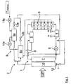
- FIG. 1 In the illustrated embodiment of a motor vehicle cooling system, as used, for example, in modern commercial vehicles, especially in trucks and buses, are in the high-temperature cooling circuit 1 an internal combustion engine 3, an oil heat exchanger 4, an exhaust gas heat exchanger 5, a coolant pump 6 and an air-cooled high-temperature heat exchanger 7 hydraulically and thermally integrated. Heat is removed from the aforementioned vehicle components via the cooling medium conveyed in the first cooling circuit 1, that is to say the high-temperature cooling circuit, and transmitted to the ambient air via the high-temperature heat exchanger 7.
- a thermostat 8 which regulates the coolant flow through the high-temperature heat exchanger.
- FIG. 1 illustrated cooling system via a second designed as a low-temperature circuit cooling circuit 2, in the first a charge air cooling unit 9 and an air-cooled low-temperature heat exchanger 10 are thermally and hydraulically integrated.
- this second cooling circuit 2 the coolant is cooled during operation of the internal combustion engine 3 to a temperature well below the coolant temperature in the cooling circuit 1.
- a two-stage compression 11 of the charge air is provided, which has a low-pressure compressor 11a and a high-pressure compressor 11 b.
- the cooling of the charge air takes place by means of the charge air cooling unit 9, which has a charge air intercooler 9a and a charge air main radiator 9b.
- the charge air intermediate 9a and the charge main main cooler 9b are integrated in parallel into the second cooling circuit 2 and cool the charge air by the charge air leaving the low-pressure compressor 11a flows through the charge air intercooler 9a and the charge air leaving the high-pressure compressor 11b flows through the charge main main cooler 9b.
- the charge air intermediate 9a and the main charge air cooler are each hydraulically connected downstream of a thermostatic control valve 12a, 12b, via which the distribution of the coolant throughput within the charge air cooling unit can be regulated.
- the air-cooled low-temperature heat exchanger 10 in the flow direction of the coolant in the second cooling circuit 2 is preceded by a valve which is designed as a shutdown element 13.
- a shutdown of the coolant flow rate can be realized.
- the minimum throughput such as during a low load operation or the starting phase of the internal combustion engine 3 can be reduced to 0.
- An unintentional cooling of the internal combustion engine 3 or An extension of the warm-up phase due to the usually existing minimum coolant throughput is thus reliably prevented.
- shut-off element 13 can be combined with a pressure-limiting or pressure-reducing function with which the occurrence of impermissibly high pressures in the second cooling circuit 2, which in particular can damage the low-temperature heat exchanger 10, is prevented. Furthermore, it is conceivable to combine the shut-off element 13 equipped with or without pressure-limiting or pressure-reducing function with a bypass line provided on the coolant pump side. The triggering of the switch-off element 13 takes place via signals which are generated taking into account measured values that have been recorded by the vehicle sensor system.
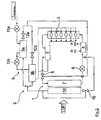
- FIG. 2 a cooling system as known in the art.
- a cooling system is located in the flow direction of the coolant in the second cooling circuit 2 in front of the Niedertemperatunrumbleübertrager 10, a bypass valve 16, by means of which a partial or total bypass of the Niedertemperatur139schreibers 10 possible.
- This circuit variant thus represents a possibility to enable a faster heating of the internal combustion engine or to avoid unwanted cooling.
- the combination of a bypass valve with the corresponding wiring is a relatively high cost.
- a bypass valve designed as a three-way valve unlike a blocking valve as a shutdown a minimum throughput on the main flow does not prevent.
Landscapes
- Engineering & Computer Science (AREA)
- Chemical & Material Sciences (AREA)
- Combustion & Propulsion (AREA)
- Mechanical Engineering (AREA)
- General Engineering & Computer Science (AREA)
- Physics & Mathematics (AREA)
- Thermal Sciences (AREA)
- Supercharger (AREA)
- Exhaust Gas After Treatment (AREA)
- Air-Conditioning For Vehicles (AREA)
- Testing Of Engines (AREA)
Description
- Die Erfindung betrifft ein Verfahren sowie ein System zum Kühlen einer Brennkraftmaschine mit Ladeluftzufuhr, das über einen ersten und einen zweiten Kühlkreislauf verfügt, von denen der erste Kühlkreislauf auf einem höheren Temperaturniveau als der zweite Kühlkreislauf betrieben wird und bei dem die Ladeluftzufuhr zumindest eine Ladeluftkühleinheit aufweist, die thermisch an den zweiten Kühlkreislauf, in dem ein Kühlmitteldurchsatz regelbar ist, gekoppelt ist.
- Moderne Brennkraftmaschinen, insbesondere Dieselmotoren, verfügen üblicherweise über eine Ladeluftkühlung, mittels der die für die Aufladung der Brennkraftmaschine benötigte Luft abgekühlt wird. Eine Ladeluftkühlung wird hierbei einerseits aufgrund der Aufheizung des Turboladers durch die Abgase des Motors benötigt. Die vorgenannte Aufheizung wird durch die gemeinsame Anordnung der Turbine und des Verdichters auf einer Welle und den damit verbundenen thermischen Kontakt der beiden Gehäuse verursacht. Augrund dieses thermischen Kontakts wird letztendlich eine Wärmeübertragung vom Abgasturbolader auf den Ladeluftverdichter verursacht.
- Andererseits ist zu berücksichtigen, dass die durch den Ladeluftverdichter angesaugte Luft üblicherweise auf eine Temperatur von etwa 180 °C oder bei einer zweistufigen Verdichtung auf eine noch höhere Temperatur erwärmt wird. Mit der steigenden Temperatur dehnt sich die angesaugte Ladeluft aus, wodurch eine Verringerung des Sauerstoffanteils je Volumeneinheit bewirkt wird. Diese Verringerung des Sauerstoffanteils bedingt eine geringere Leistungssteigerung des Motors. Um diesem Effekt entgegenzuwirken, werden insbesondere bei Kraftfahrzeugmotoren die eingangs erwähnten Ladeluftkühler auch verwendet. Der Einsatz eines Ladeluftkühlers stellt sicher, dass die aufgeheizte Luft heruntergekühlt und dadurch dem Verbrennungsvorgang im Zylinder eine höhere Ladungsdichte zur Verfügung gestellt wird. Durch den höheren Sauerstoffgehalt der Ladeluft pro Volumeneinheit ist es somit möglich, eine größere Kraftstoffmenge zu verbrennen. Dies führt zu einer nochmaligen Leistungssteigerung, die etwa 30 % betragen kann. Gleichzeitig wird durch die Ladeluftkühlung die Stickoxidemission reduziert, da aufgrund der geringeren Ladelufteintrittstemperatur auch niedrigere Verbrennungstemperaturen erzielt werden.
- In diesem Zusammenhang ist aus der
DE 102 46 807 A1 ein Kühlsystem für Brennkraftmaschinen mit indirekter Ladeluftkühlung bekannt. Bei dem beschriebenen Kühlsystem sind in einem Kühlkreislauf zwei luftgekühlte Wärmeübertrager sowie ein Ladeluftkühler vorgesehen. Das Kühlsystem verfügt hierbei über einen Aggregatkühlkreislauf zur Kühlung eines Verbrennungsmotors, der einen Hauptkühlkreislauf mit Hauptkühlmittelkühler und einen Zusatzkühlkreislauf zur Kühlung eines Zusatzmediums umfasst. Der Zusatzkühlkreislauf zweigt an einer Auskoppelstelle vom Hauptkühlkreislauf ab und führt zu diesem an einer Einkoppelstelle, die zwischen dem Hauptkühlmittelkühler und einer Kühlmittelförderpumpe angeordnet ist, zurück. Zusätzlich zu den beiden vorgenannten Kühlern ist ein Ladeluftkühler vorgesehen, mit dem die der Brennkraftmaschine zugeführte Ladeluft gekühlt wird. Wesentlich an der beschriebenen technischen Lösung ist, dass die Kühlkreisläufe auf unterschiedlichen Temperaturniveaus betreibbar sind und die Kühlmittelförderpumpe hinsichtlich des zu fördernden Volumenstroms, der Förderleistung und/oder des Förderdrucks verstellbar ist. - In Ergänzung zu der zuvor zitierten Veröffentlichung ist bspw. aus der
DE 10 2006 010 247 ein Kühlsystem für aufgeladene Kraftfahrzeugmotoren bekannt, bei dem die Ladeluftkühleinheit einen Ladeluftzwischen- und einen Ladelufthauptkühler aufweist. Da die Ladeluft in diesem Fall zweistufig verdichtet wird, wird mit dem Ladeluftzwischenkühler die Ladeluft zwischen dem Niederdruckverdichter und dem Hochdruckverdichter gekühlt, während der Ladelufthauptkühler die Ladeluft abkühlt, die den Hochdruckverdichter verlassen hat. - Nachteilig an den zuvor beschriebenen Systemen ist, dass der jeweils auf einem niedrigeren Temperaturniveau betriebene Kühlkreislauf, in den bspw. auch die Ladeluftkühler eingekoppelt sind, in allen Betriebszuständen mit einem Kühlmittel beaufschlagt wird, so dass die entsprechenden Motorkomponenten während des Betriebs der Brennkraftmaschine zu jeder Zeit gekühlt werden. Unabhängig vom Mindestkühlmitteldurchsatz im Niedertemperaturkühlkreislauf gibt es jedoch Betriebszustände der Brennkraftmaschine, wie etwa die Startphase oder bestimmte Phasen zur Regeneration von Abgasnachbehandlungskomponenten, in denen eine erhöhte Temperatur benötigt wird.
- In der
DE 102 15 262 A1 ist ein Kühlsystem für einen Kraftfahrzeugmotor mit indirekter Ladeluftkühlung beschrieben. Das Kühlsystem umfasst einen Aggregatkühlkreislauf und einen Zusatzkühlkreislauf. Im Kühlsystem sind Mittel zur Kühlmitteltemperaturerfassung und zur Regulierung des Kühlmittelflusses vorgesehen. - Aus der
WO 2005/061869 A1 ist eine Kreislaufanordnung zur Kühlung von Ladeluft bekannt. Am Kühlmittelaustritt eines Ladeluft-Kühlmittelkühlers oder kurz danach ist ein TemperaturSensor zur Messung der Kühlmittelaustritts-Temperatur vorgesehen. - Die
WO 2004/090303 A1 beschreibt eine Kreislaufanordnung zur Kühlung von Ladeluft mit einem Niedertemperatur-Kreislauf und einem Motorkühl-Kreislauf. Der Niedertemperatur-Kreislauf ist mit dem Motor-Kreislauf derart zeitweise koppelbar, dass Kühlmittel von einem Kreislauf in den anderen Kreislauf und zurück gelangen kann. - In der
WO 2005/012707 A1 ist eine Kreislaufanordnung zur Kühlung von Ladeluft bei einem Kraftfahrzeug beschrieben. In der Kreislaufanordnung ist eine zweistufige Verdichtung der Ladeluft vorgesehen, wobei zur Kühlung der Ladeluft nach einem Niederdruck-Turbolader und vor einem Hochdruck-Turbolader ein erster Kühler und nach dem Hochdruck-Turbolader und vor dem Motor ein zweiter Kühler vorgesehen ist. - Der Erfindung liegt die Aufgabe zugrunde, ein Kühlsystem für eine aufgeladene Brennkraftmaschine zu schaffen, bei dem in bestimmten, auswählbaren Betriebszuständen das durch den Mindestdurchsatz des Kühlmittels im Niedertemperaturkühlkreislauf verursachte Auskühlen der Brennkraftmaschine zuverlässig verhindert wird. Hierbei sollen insbesondere Warmlaufphasen der Brennkraftmaschine verkürzt sowie auch innerhalb kürzester Zeit eine zeitweise Anhebung des Ladelufttemperatumiveaus, vor allem in Hinblick auf bestimmte Regenerationsstrategien von Abgasnachbehandlungskomponenten erreicht werden. Das anzugebende Kühlsystem soll vor allem regelungstechnisch verhältnismäßig einfach gestaltet sein und auch eine kurzfristige Reaktion auf Veränderungen der Betriebsparameter der Brennkraftmaschine, eines nachgeschalteten Abgasbehandlungssystems und/oder der Zustandsgrößen in den Kühlkreisläufen ermöglichen.
- Die vorstehend genannte Aufgabe wird mit Hilfe eines Kühlsystems, das über die im Patentanspruch 1 angegebenen Merkmale verfügt, gelöst. Darüber hinaus ist im Anspruch 5 ein Verfahren, mit dem die der Erfindung zugrunde liegende Aufgabe gelöst wird, angegeben. Vorteilhafte Ausführungsformen der Erfindung sind Gegenstand der abhängigen Ansprüche und werden in der Beschreibung unter Bezugnahme auf die Figuren näher erläutert.
- Gemäß Anspruch 1 ist ein Kühlsystem einer Brennkraftmaschine mit Ladeluftzufuhr vorgesehen, das über einen ersten und einen zweiten Kühlkreislauf verfügt, von denen der erste Kühlkreislauf auf einem höherem Temperatumiveau als der zweite Kühlkreislauf betrieben wird und bei dem die Ladeluftzufuhr zumindest eine Ladeluftkühleinheit aufweist, die thermisch an den zweiten, einen regelbaren Kühlmitteldurchsatz aufweisenden Kühlkreislauf gekoppelt ist. Erfindungsgemäß ist im zweiten Kühlkreislauf wenigstens ein Abschaltelement vorgesehen, mit dem während eines Betriebs der Brennkraftmaschine in Abhängigkeit eines Betriebsparameters oder einer Zustandsänderung wenigstens einer Fahrzeugkomponente der Kühlmitteldurchsatz im zweiten Kühlkreislauf auf Null drosselbar, also abschaltbar ist, wobei die Fahrzeugkomponente ein Abgasnachbehandlungssystem ist.
- Die zuvor beschriebene Erfindung zeichnet sich somit insbesondere dadurch aus, dass der Kühlmitteldurchsatz im Niedertemperaturkreislauf in Abhängigkeit von auswählbaren bzw. in einer zentralen Steuereinheit hinterlegbarer Betriebsparameter oder Zustandsänderungen eines Abgasnachbehandlungssystems vollständig abschaltbar ist. Mit einem Kühlsystem, das gemäß der Erfindung ausgeführt ist, ist es möglich, auch während des Betriebs der Brennkraftmaschine den ansonsten üblichen Kühlmittelmindestdurchsatz im Niedertemperaturkreislauf in Abhängigkeit eines vorgebbaren, betriebsspezifischen Entscheidungskriteriums zumindest zeitweise vollständig abzuschalten. Auf diese Weise wird in bestimmten Betriebszuständen, die vorab festgelegt sind, das ansonsten durch den Mindestkühlmitteldurchsatz verursachte Auskühlen des Motors sowie bestimmter thermisch an den Niedertemperaturkreislauf gekoppelter Komponenten eines Abgasnachbehandlungssystems zuverlässig unterbunden.
- In einer vorteilhaften Ausführungsform der Erfindung wird das Kühlsystem mit einer zweistufigen Ladeluftverdichtung kombiniert. Diese technische Lösung zeichnet sich dadurch aus, dass die Ladeluftzufuhr über ein Niederdruck- und einen Hochdruckverdichter und die Ladeluftkühleinheit über einen Ladeluftzwischen- sowie einen Ladelufthauptkühler verfügt. Der Ladeluftzwischenkühler ist in Strömungsrichtung der Ladeluft zwischen den Niederdruck- und den Hochdruckverdichter geschaltet, während der Ladelufthauptkühler dem Hochdruckverdichter nachgeschaltet ist. In diesem Zusammenhang ist es vorteilhafterweise denkbar, dem Ladeluftzwischenkühler und/oder dem Ladelufthauptkühler im Niedertemperaturkühlkreislauf ein Thermostatventil nachzuschalten, so dass der Kühlmitteldurchsatz durch die beiden Kühler in Abhängigkeit der im zweiten Kühlkreislauf in Strömungsrichtung des Kühlmittels hinter den Ladeluftkühlern auftretenden Temperatur oder Temperaturen regelbar ist.
- Weiterhin sieht eine vorteilhafte Weiterbildung vor, dass das im zweiten Kühlkreislauf vorgesehene Abschaltelement über ein Überdruckventil verfügt. Mit Hilfe des vorbeschriebenen Überdruckventils wird in den zweiten Kühlkreislauf eine Druckbegrenzungsfunktion integriert, so dass bei Bedarf insbesondere der luftgekühlte Niedertemperaturwärmeübertrager, also der Wärmeübertrager, über den Wärme aus dem zweiten Kühlkreislauf an die Umgebung übertragen wird, vor unzulässigen Druckspitzen geschützt wird.
- Neben dem zuvor beschriebenen Kühlsystem betrifft die Erfindung auch ein Verfahren zum Kühlen einer Brennkraftmaschine. Hierbei wird die Brennkraftmaschine über eine Ladeluftzufuhr mit Ladeluft aufgeladen und das Kühlmittel wird in einem ersten und einem zweiten Köhlmittelkreislauf umgewälzt. Der erste Kühlkreislauf wird auf einem höheren Temperatumiveau als der zweite Kühlkreislauf betrieben und die Ladeluftzufuhr weist zumindest eine Ladeluftkühleinheit auf, wobei die Wärme aus der Ladeluft an den zweiten Kühlkreislauf übertragen wird, dessen Kühlmitteldurchsatz vorzugsweise in Abhängigkeit fahrzeugspezifischer Betriebsparameter geregelt wird. Das erfindungsgemäß ausgeführte Verfahren zeichnet sich dadurch aus, dass während eines Betriebs der Brennkraftmaschine in Abhängigkeit eines Betriebsparameters oder einer Zustandsänderung einer Fahrzeugkomponente und/oder anderer Einflussgrößen der Kühlmitteldurchsatz im zweiten Kühlkreislauf auf Null gedrosselt, also abgeschaltet wird, wobei der Kühlmitteldurchsatz in Abhängigkeit zumindest einer Komponente eines Abgasnachbehandlungssystems abgeschaltet wird.
- Im Weiteren wird die Erfindung unter Bezugnahme auf die Figuren näher erläutert.
- Es zeigen:
- Fig. 1:
- Kühlsystem mit Hoch- sowie Niedertemperaturkühlkreislauf und einem Abschaltelement im Niedertemperaturkühlkreislauf;
- Fig. 2:
- Kühlsystem mit Hoch- sowie Niedertemperaturkühlkreislauf ohne Abschaltelement im Niedertemperaturkühlkreislauf.
- Die
Figur 1 zeigt ein erfindungsgemäß ausgeführtes Kühlsystem mit einem ersten als Hochtemperaturkreislauf ausgelegten Kühlkreislauf 1 und einem zweiten als Niedertemperaturkreislauf ausgelegten Kühlkreislauf 2. Bei dem dargestellten Ausführungsbeispiel eines Kraftfahrzeugkühlsystems, wie es bspw. in modernen Nutzfahrzeugen, insbesondere in Lastkraftwagen und Omnibussen, zum Einsatz kommt, sind in den Hochtemperaturkühlkreislauf 1 eine Brennkraftmaschine 3, ein Olwärmetauscher 4, ein Abgaswärmetauscher 5, eine Kühlmittelpumpe 6 und ein luftgekühlter Hochtemperaturwärmeübertrager 7 hydraulisch und thermisch eingebunden. Über das im ersten Kühlkreislauf 1, also dem Hochtemperaturkühlkreislauf, geförderte Kühlmedium wird Wärme aus den vorgenannten Fahrzeugkomponenten abgeführt und über den Hochtemperaturwärmeübertrager 7 an die Umgebungsluft übertragen. - Innerhalb des ersten Kühlkreislaufes 1 ist ein Thermostat 8 vorgesehen, das den Kühlmitteldurchfluss durch den Hochtemperaturwärmeübertrager regelt. Des Weiteren verfügt das in
Figur 1 dargestellte Kühlsystem über einen zweiten als Niedertemperaturkreislauf ausgeführten Kühlkreislauf 2, in den zunächst eine Ladeluftkühleinheit 9 sowie ein luftgekühlter Niedertemperaturwärmeübertrager 10 thermisch und hydraulisch eingebunden sind. In diesem zweiten Kühlkreislauf 2 wird das Kühlmittel während des Betriebs der Brennkraftmaschine 3 auf eine Temperatur deutlich unter der Kühlmitteltemperatur im Kühlkreislauf 1 abgekühlt. - Um eine optimale Aufladung der Brennkraftmaschine 3 zu realisieren, ist eine zweistufige Verdichtung 11 der Ladeluft vorgesehen, die über einen Niederdruckverdichter 11a und einen Hochdruckverdichter 11 b verfügt. Die Kühlung der Ladeluft erfolgt mittels der Ladeluftkühleinheit 9, die einen Ladeluftzwischenkühler 9a und einen Ladelufthauptkühler 9b aufweist. Hydraulisch sind der Ladeluftzwischen- 9a und der Ladelufthauptkühler 9b parallel in den zweiten Kühlkreislauf 2 eingebunden und kühlen die Ladeluft indem die den Niederdruckverdichter 11a verlassende Ladeluft den Ladeluftzwischenkühler 9a und die den Hochdruckverdichter 11 b verlassende Ladeluft den Ladelufthauptkühler 9b durchströmt.
- Im zweiten Kühlkreislauf 2 ist dem Ladeluftzwischen- 9a und dem Ladelufthauptkühler hydraulisch jeweils ein Thermostatregelventil 12a, 12b nachgeschaltet, über die die Aufteilung des Kühlmitteldurchsatzes innerhalb der Ladeluftkühleinheit regelbar ist.
- Ferner ist dem luftgekühlten Niedertemperaturwärmeübertrager 10 in Strömungsrichtung des Kühlmittels im zweiten Kühlkreislauf 2 ein Ventil vorgeschaltet, das als Abschaltelement 13 ausgeführt ist. In Abhängigkeit eines Betriebsparameters oder einer Zustandsänderung einer durch ein Abgasnachbehandlungssystem gebildeten Fahrzeugkomponente kann eine Abschaltung des Kühlmitteldurchsatzes realisiert werden. Auf diese Weise kann der Mindestdurchsatz, etwa während eines Schwachlastbetriebs oder der Startphase der Brennkraftmaschine 3 auf 0 reduziert werden. Ein ungewolltes Auskühlen der Brennkraftmaschine 3 oder eine Verlängerung der Warmlaufphase aufgrund des üblicherweise vorhandenen Kühlmittelmindestdurchsatzes wird somit zuverlässig verhindert.
- Zusätzlich kann das Abschaltelement 13 mit einer Druckbegrenzungs- oder Druckminderfunktion kombiniert werden mit der das Auftreten unzulässig hoher Drücke im zweiten Kühlkreislauf 2, die insbesondere den Niedertemperaturwärmeübertrager 10 beschädigen können, unterbunden wird. Ferner ist es denkbar, das mit oder ohne Druckbegrenzungs- bzw. Druckminderfunktion ausgerüstete Abschaltelement 13 mit einer auf der Kühlmittelpumpenseite vorgesehenen Bypassleitung zu kombinieren. Die Ansteuerung des Abschaltelements 13 erfolgt über Signale, die unter Berücksichtigung von Messwerten, die von der Fahrzeugsensorik aufgenommen worden sind, generiert werden.
- Im Vergleich zur
Figur 1 zeigt dieFigur 2 ein Kühlsystem, wie es aus dem Stand der Technik bekannt ist. Bei dieser Ausführung eines Kühlsystems befindet sich in Strömungsrichtung des Kühlmittels im zweiten Kühlkreislauf 2 vor dem Niedertemperatunrwärmeübertrager 10 ein Bypassventil 16, mittels dem eine teilweise oder gänzliche Umgehung des Niedertemperaturwärmeübertragers 10 möglich. Auch diese Schaltungsvariante stellt somit eine Möglichkeit dar, eine schnellere Aufheizung der Brennkraftmaschine zu ermöglichen oder ein ungewolltes Auskühlen zu vermeiden. Im Gegensatz zur erfindungsgemäßen technischen Lösung stellt die Kombination eines Bypassventils mit der entsprechenden Leitungsführung einen verhältnismäßig hohen Aufwand dar. Darüber hinaus kann ein als Dreiwegeventil ausgeführtes Bypassventil im Unterschied zu einem sperrenden Ventil als Abschaltelement einen Mindestdurchsatz auf dem Hauptströmungsweg nicht verhindern. -
- 1
- erster Kühlkreislauf (Hochtemperaturkühlkreislauf)
- 2
- zweiter Kühlkreislauf (Niedertemperaturkühlkreislauf)
- 3
- Brennkraftmaschine
- 4
- Ölwärmetauscher
- 5
- Abgaswärmetauscher
- 6
- Kühlmittelpumpe
- 7
- Hochtemperaturwärmeübertrager
- 8
- Motorthermostat
- 9
- Ladeluftkühleinheit
- a) Ladeluftzwischenkühler
- b) Ladelufthauptkühler
- 10
- Niedertemperaturwärmeübertrager
- 11
- Verdichter
- a) Niederdruckverdichter
- b) Hochdruckverdichter
- 12 a, b
- Thermostatventile
- 13
- Abschaltelement
- 16
- Bypassventil
Claims (5)
- Kühlsystem einer Brennkraftmaschine (3) mit Ladeluftzufuhr, das über einen ersten (1) und einen zweiten (2) Kühlkreislauf verfügt, von denen der erste Kühlkreislauf (1) auf einem höheren Temperatumiveau als der zweite Kühlkreislauf (2) betrieben wird und bei dem die Ladeluftzufuhr zumindest eine Ladeluftkühleinheit (9) aufweist, die thermisch an den zweiten, einen regelbaren Kühlmitteldurchsatz aufweisenden Kühlkreislauf (2) gekoppelt ist, dadurch gekennzeichnet, dass im zweiten Kühlkreislauf (2) wenigstens ein Abschaltelement (13) vorgesehen ist, mit dem während eines Betriebs der Brennkraftmaschine (3) in Abhängigkeit eines Betriebsparameters einer Fahrzeugkomponente der Kühlmitteldurchsatz im zweiten Kühlkreislauf (2) auf Null drosselbar, also abschaltbar ist, wobei die Fahrzeugkomponente ein Abgasnachbehandlungssystem ist.
- Kühlsystem nach Anspruch 1, dadurch gekennzeichnet, dass die Ladeluftzufuhr über einen Niederdruck- (11a) und einen Hochdruckverdichter (11b) und die Ladeluftkühleinheit (9) über einen Zwischen- (9a) und einen Hauptkühler (9b) verfügt, von denen der Zwischenkühler (9a) in Strömungsrichtung der Ladeluft zwischen den Niederdruck- (11 a) und den Hochdruckverdichter (11b) geschaltet ist und der Hauptkühler (9b) dem Hochdruckverdichter (111b) nachgeschaltet ist.
- Kühlsystem nach Anspruch 1 oder 2, dadurch gekennzeichnet, dass der Ladeluftkühleinheit (9) in Strömungsrichtung des Kühlmittels zumindest ein Temperatursensor sowie eine regelungstechnisch mit dem Temperatursensor in Wirkverbindung stehende Armatur nachgeschaltet ist.
- Kühlsystem nach einem der Ansprüche 1 bis 3, dadurch gekennzeichnet, dass das Abschaltelement (13) mit einer Druckminder- oder Druckbegrenzungsfunktion kombiniert oder mit einem Druckminder- oder Druckbegrenzungsventil in Reihe geschaltet wird.
- Verfahren zum Kühlen einer Brennkraftmaschine (3), die über eine Ladeluftzufuhr mit Ladeluft aufgeladen wird, bei dem ein Kühlmittel in einem ersten (1) und einem zweiten (2) Kühlkreislauf umgewälzt wird, wobei der erste Kühlkreislauf (1) auf einem höheren Temperatumiveau als der zweite Kühlkreislauf (2) betrieben wird und die Ladeluftzufuhr zumindest eine Ladeluftkühleinheit (9) aufweist, die Wärme aus der Ladeluft an den zweiten Kühlkreislauf (2), in dem ein Kühlmitteldurchsatz geregelt wird, übertragen wird, dadurch gekennzeichnet, dass während eines Betriebs der Brennkraftmaschine (3) in Abhängigkeit eines Betriebsparameters oder einer Zustandsänderung einer Fahrzeugkomponente und/oder anderer Einflussgrößen der Kühlmitteldurchsatz im zweiten Kühlkreislauf (2) auf Null gedrosselt, also abgeschaltet wird, wobei der Kühlmitteldurchsatz in Abhängigkeit zumindest einer Komponente eines Abgasnachbehandlungssystems abgeschaltet wird.
Priority Applications (1)
| Application Number | Priority Date | Filing Date | Title |
|---|---|---|---|
| PL07017147T PL1905978T3 (pl) | 2006-09-20 | 2007-08-31 | Układ chłodzenia doładowanego silnika spalinowego z chłodnicą powietrza doładowującego |
Applications Claiming Priority (1)
| Application Number | Priority Date | Filing Date | Title |
|---|---|---|---|
| DE102006044820.0A DE102006044820B4 (de) | 2006-09-20 | 2006-09-20 | Kühlsystem einer Brennkraftmaschine mit Ladeluftzufuhr |
Publications (3)
| Publication Number | Publication Date |
|---|---|
| EP1905978A2 EP1905978A2 (de) | 2008-04-02 |
| EP1905978A3 EP1905978A3 (de) | 2010-01-13 |
| EP1905978B1 true EP1905978B1 (de) | 2016-01-27 |
Family
ID=38819783
Family Applications (1)
| Application Number | Title | Priority Date | Filing Date |
|---|---|---|---|
| EP07017147.5A Active EP1905978B1 (de) | 2006-09-20 | 2007-08-31 | Kühlsystem einer aufgeladenen Brennkraftmaschine mit Ladeluftkühler |
Country Status (7)
| Country | Link |
|---|---|
| US (1) | US7874154B2 (de) |
| EP (1) | EP1905978B1 (de) |
| CN (1) | CN101225764B (de) |
| BR (1) | BRPI0704877A (de) |
| DE (1) | DE102006044820B4 (de) |
| PL (1) | PL1905978T3 (de) |
| RU (1) | RU2349768C1 (de) |
Families Citing this family (37)
| Publication number | Priority date | Publication date | Assignee | Title |
|---|---|---|---|---|
| US8091360B2 (en) * | 2005-08-03 | 2012-01-10 | Amovis Gmbh | Driving device |
| SE532245C2 (sv) * | 2008-04-18 | 2009-11-24 | Scania Cv Ab | Kylarrangemang hos en överladdad förbränningsmotor |
| SE533750C2 (sv) * | 2008-06-09 | 2010-12-21 | Scania Cv Ab | Arrangemang hos en överladdad förbränningsmotor |
| SE533942C2 (sv) * | 2008-06-09 | 2011-03-08 | Scania Cv Ab | Arrangemang hos en överladdad förbränningsmotor |
| JP5470384B2 (ja) * | 2008-07-16 | 2014-04-16 | ボーグワーナー インコーポレーテッド | エンジンシステムの冷却サブシステムの、そのサブシステム内で検出された動圧に応じた診断 |
| SE532729C2 (sv) * | 2008-08-22 | 2010-03-23 | Scania Cv Ab | Kylsystem hos ett fordon som drivs av en förbränningsmotor |
| AT507096B1 (de) * | 2008-12-10 | 2010-02-15 | Man Nutzfahrzeuge Oesterreich | Antriebseinheit mit kühlkreislauf und separatem wärmerückgewinnungskreislauf |
| DE102009006966A1 (de) | 2009-01-31 | 2010-08-05 | Volkswagen Ag | Verfahren zum Regeln eines Ladeluftkühlers |
| US9551273B2 (en) * | 2009-03-23 | 2017-01-24 | Calsonic Kansei Corporation | Charge air cooling system |
| DE102009002890B4 (de) * | 2009-05-07 | 2019-03-07 | Robert Bosch Gmbh | Verfahren und Vorrichtung zur Überwachung eines Ladeluftkühler-Bypass-Ventils |
| DE102010005824A1 (de) * | 2010-01-27 | 2011-07-28 | GM Global Technology Operations LLC, ( n. d. Ges. d. Staates Delaware ), Mich. | Flüssigkeitskühlsystem eines durch einen Turbolader aufgeladenen Verbrennungsmotors und Verfahren zur Kühlung eines Turbinengehäuses eines Turboladers |
| SE535877C2 (sv) * | 2010-05-25 | 2013-01-29 | Scania Cv Ab | Kylarrangemang hos ett fordon som drivs av en överladdad förbränningsmotor |
| US8091359B2 (en) | 2010-06-03 | 2012-01-10 | Ford Global Technologies, Llc | Exhaust heat recovery for engine heating and exhaust cooling |
| JP5614235B2 (ja) * | 2010-10-21 | 2014-10-29 | いすゞ自動車株式会社 | 二段過給システムの吸気冷却装置 |
| SE535564C2 (sv) * | 2010-12-22 | 2012-09-25 | Scania Cv Ab | Kylsystem i ett fordon |
| US8960135B2 (en) | 2011-02-28 | 2015-02-24 | Cummins Intellectual Property, Inc. | Ejector coolant pump for internal combustion engine |
| DE102011075617B4 (de) * | 2011-05-10 | 2013-05-08 | Mtu Friedrichshafen Gmbh | Verfahren zur Führung einer Ladeluft, Anschlusskasten für eine Kühleranordnung und Kühleranordnung für eine Brennkraftmaschine und Brennkraftmaschine mit einer zweistufigen Aufladung |
| DE102011076457A1 (de) * | 2011-05-25 | 2012-11-29 | Ford Global Technologies, Llc | Kühlanordnung für eine aufladbare Brennkraftmaschine |
| GB2492769A (en) * | 2011-07-11 | 2013-01-16 | Gm Global Tech Operations Inc | Engine system with an additional circuit collecting heat |
| US20150068472A1 (en) | 2011-09-16 | 2015-03-12 | Tokyo Raidator Mfg. Co., Ltd. | EGR Gas Cooling System |
| JP2013113182A (ja) | 2011-11-28 | 2013-06-10 | Calsonic Kansei Corp | エンジンの冷却装置及びその冷却方法 |
| JP5664586B2 (ja) * | 2012-04-05 | 2015-02-04 | 株式会社デンソー | 内燃機関の吸気システム |
| US9097174B2 (en) * | 2012-05-11 | 2015-08-04 | Delphi Technologies, Inc. | System and method for conditioning intake air to an internal combustion engine |
| DE102013215608A1 (de) * | 2013-08-07 | 2015-02-12 | Behr Gmbh & Co. Kg | Kühlsystem und zugehöriges Betriebsverfahren |
| CN103437876B (zh) * | 2013-09-17 | 2016-08-17 | 南车戚墅堰机车有限公司 | 柴油发电机组辅助水冷却系统 |
| US9551275B2 (en) | 2014-08-07 | 2017-01-24 | Caterpillar Inc. | Cooling system having pulsed fan control |
| JP6582777B2 (ja) * | 2015-09-15 | 2019-10-02 | いすゞ自動車株式会社 | エンジンの冷却システム |
| CN106555631B (zh) * | 2015-09-29 | 2019-02-05 | 日立汽车系统(苏州)有限公司 | 发动机系统及其控制方法 |
| FR3043719B1 (fr) * | 2015-11-13 | 2019-07-05 | Novares France | Circuit de refroidissement pour un vehicule automobile |
| SE541691C2 (en) * | 2016-05-19 | 2019-11-26 | Scania Cv Ab | A cooling system for a combustion engine and a further object |
| DE102016014904A1 (de) * | 2016-12-15 | 2018-06-21 | Deutz Aktiengesellschaft | Brennkraftmaschine |
| US10920656B2 (en) * | 2017-06-09 | 2021-02-16 | Pratt & Whitney Canada Corp. | Internal combustion engine cooling system |
| DE102017219939A1 (de) * | 2017-11-09 | 2019-05-09 | Volkswagen Aktiengesellschaft | Kühlkreislauf für eine Antriebseinheit eines Kraftfahrzeuges |
| CN107939509B (zh) * | 2017-11-20 | 2020-11-03 | 潍柴动力股份有限公司 | 一种发动机的两级增压级间冷却控制系统及控制方法 |
| CN108361098A (zh) * | 2018-03-22 | 2018-08-03 | 潍柴动力股份有限公司 | 两级增压中冷发动机的冷却系统 |
| DE102019218390A1 (de) | 2019-11-27 | 2021-05-27 | Mahle International Gmbh | Kühlsystem und eine Kühlanordnung für ein Kraftfahrzeug |
| DE102020007769A1 (de) | 2020-12-18 | 2022-06-23 | Mercedes-Benz Group AG | Kühlvorrichtung zum Kühlen von Ladeluft |
Family Cites Families (24)
| Publication number | Priority date | Publication date | Assignee | Title |
|---|---|---|---|---|
| US3134371A (en) * | 1962-10-29 | 1964-05-26 | Cooper Bessemer Corp | Cooling system for internal combustion engines |
| SU530102A1 (ru) * | 1974-04-12 | 1976-09-30 | Дальневосточный Ордена Трудового Красного Знамени Политехнический Институт Имени В.В.Куйбышева | Способ снабжени воздухом двигател внутреннего сгорани с наддувом |
| SU676743A1 (ru) * | 1977-10-17 | 1979-07-30 | Предприятие П/Я М-5536 | Система охлаждени двигател внутреннего сгорани |
| DE2923852A1 (de) * | 1978-06-16 | 1979-12-20 | Garrett Corp | Ladeluftkuehlsystem |
| US4317439A (en) * | 1979-08-24 | 1982-03-02 | The Garrett Corporation | Cooling system |
| DE3517567A1 (de) * | 1984-05-29 | 1985-12-05 | Volkswagenwerk Ag, 3180 Wolfsburg | Antriebsanlage fuer geraete und fahrzeuge, insbesondere kraftfahrzeuge |
| DE3519320C2 (de) * | 1985-05-30 | 1987-04-23 | Dr.Ing.H.C. F. Porsche Ag, 7000 Stuttgart | Flüssigkeitskühlsystem für eine aufgeladene Brennkraftmaschine |
| DE3608294A1 (de) * | 1986-03-13 | 1987-09-17 | Kloeckner Humboldt Deutz Ag | Fluessigkeitskuehlsystem fuer eine brennkraftmaschine |
| SU1333796A1 (ru) * | 1986-04-29 | 1987-08-30 | Московский автомеханический институт | Система охлаждени двигател внутреннего сгорани с наддувом |
| US5598705A (en) * | 1995-05-12 | 1997-02-04 | General Motors Corporation | Turbocharged engine cooling apparatus |
| US5910099A (en) * | 1997-02-28 | 1999-06-08 | General Motors Corporation | Turbocharged engine cooling system control with fuel economy optimization |
| DE19924677A1 (de) | 1999-05-29 | 2000-08-10 | Daimler Chrysler Ag | Ansaugsystem für eine Brennkraftmaschine |
| DE10139315A1 (de) | 2001-08-09 | 2003-03-06 | Deere & Co | Kühlsystem für einen Verbrennungsmotor |
| DE10155339A1 (de) * | 2001-11-10 | 2003-05-22 | Daimler Chrysler Ag | Verfahren zum Betreiben eines Verbrennungsmotors und Kraftfahrzeug |
| ATE469292T1 (de) * | 2002-03-08 | 2010-06-15 | Behr Gmbh & Co Kg | Vorrichtung zur kühlung von ladeluft und verfahren zum betreiben einer derartigen vorrichtung |
| DE10215262B4 (de) | 2002-04-06 | 2014-12-31 | Daimler Ag | Kühlsystem, insbesondere für einen Kraftfahrzeugmotor mit indirekter Ladeluftkühlung |
| DE10317003A1 (de) | 2003-04-11 | 2004-12-09 | Behr Gmbh & Co. Kg | Kreislaufanordnung zur Kühlung von Ladeluft und Verfahren zum Betreiben einer derartigen Kreislaufanordnung |
| DE10335567A1 (de) * | 2003-07-31 | 2005-03-10 | Behr Gmbh & Co Kg | Kreislaufanordnung zur Kühlung von Ladeluft und Verfahren zum Betreiben einer derartigen Kreislaufanordnung |
| ATE502193T1 (de) | 2003-12-19 | 2011-04-15 | Behr Gmbh & Co Kg | Kreislaufanordnung zur kühlung von ladeluft und verfahren zum betreiben einer derartigen kreislaufanordnung |
| DE502005008822D1 (de) * | 2004-02-01 | 2010-02-25 | Behr Gmbh & Co Kg | Anordnung zur kühlung von abgas und ladeluft |
| DE102004033704B4 (de) * | 2004-07-13 | 2010-11-04 | Man Nutzfahrzeuge Ag | Ladeluftkühler für eine zweistufig aufgeladene Brennkraftmaschine |
| US7254947B2 (en) * | 2005-06-10 | 2007-08-14 | Deere & Company | Vehicle cooling system |
| US20090020079A1 (en) * | 2005-11-10 | 2009-01-22 | BEHRmbH & Co. KG | Circulation system, mixing element |
| DE102006010247B4 (de) * | 2006-03-02 | 2019-12-19 | Man Truck & Bus Se | Antriebseinheit mit Wärmerückgewinnung |
-
2006
- 2006-09-20 DE DE102006044820.0A patent/DE102006044820B4/de not_active Expired - Fee Related
-
2007
- 2007-08-31 PL PL07017147T patent/PL1905978T3/pl unknown
- 2007-08-31 EP EP07017147.5A patent/EP1905978B1/de active Active
- 2007-09-18 US US11/901,512 patent/US7874154B2/en active Active
- 2007-09-19 RU RU2007134888/06A patent/RU2349768C1/ru active
- 2007-09-20 BR BRPI0704877-7A patent/BRPI0704877A/pt not_active IP Right Cessation
- 2007-09-20 CN CN2007101527568A patent/CN101225764B/zh not_active Expired - Fee Related
Also Published As
| Publication number | Publication date |
|---|---|
| EP1905978A3 (de) | 2010-01-13 |
| DE102006044820B4 (de) | 2019-03-07 |
| CN101225764A (zh) | 2008-07-23 |
| EP1905978A2 (de) | 2008-04-02 |
| CN101225764B (zh) | 2012-09-05 |
| RU2349768C1 (ru) | 2009-03-20 |
| PL1905978T3 (pl) | 2016-07-29 |
| BRPI0704877A (pt) | 2008-09-16 |
| US20080066697A1 (en) | 2008-03-20 |
| DE102006044820A1 (de) | 2008-04-03 |
| US7874154B2 (en) | 2011-01-25 |
Similar Documents
| Publication | Publication Date | Title |
|---|---|---|
| DE102006044820B4 (de) | Kühlsystem einer Brennkraftmaschine mit Ladeluftzufuhr | |
| EP1716325B1 (de) | Anordnung zur kühlung von abgas und ladeluft | |
| EP1651846B1 (de) | Kreislaufanordnung zur kühlung von ladeluft und verfahren zum betreiben einer derartigen kreislaufanordnung | |
| DE102014206644B4 (de) | Aufgeladene Brennkraftmaschine und Verfahren zum Betreiben einer derartigen Brennkraftmaschine | |
| DE102014002940B4 (de) | Motorkühlsystem mit temperaturabhängiger Steuerung des Kühlmittelwegs | |
| DE102009015656B4 (de) | Modulare Abgasrückführungsanlage, Motorsystem und Verfahren zum Kühlen eines Abgasrückführungsgasstroms | |
| EP1616087B1 (de) | Kreislaufanordnung zur kühlung von ladeluft und verfahren zum betreiben einer derartigen kreislaufanordnung | |
| EP2213859B1 (de) | Verfahren zum Regeln eines Ladeluftkühlers | |
| EP1623101B1 (de) | Kreislauf zur k hlung von ladeluft und verfahren zum betreib en eines derartigen kreislaufs | |
| EP3051114B1 (de) | Brennkraftmaschine mit agr-kühler | |
| DE102011076457A1 (de) | Kühlanordnung für eine aufladbare Brennkraftmaschine | |
| EP1342892B1 (de) | Kreislauf zur Kühlung von Ladeluft und Verfahren zum Betreiben eines derartigen Kreislaufs | |
| EP3530899A1 (de) | Kühlsystem und brennkraftmaschine | |
| EP3530901A1 (de) | Brennkraftmaschine | |
| WO2009036889A1 (de) | Vorrichtung für die ladeluftkühlung sowie verfahren zur ladeluftkühlung | |
| DE102008015591A1 (de) | Aufgeladene Brennkraftmaschine mit Abgasrückführung | |
| KR101946683B1 (ko) | 내연기관용 냉각 시스템 및 방법 | |
| EP2212540B1 (de) | Vorrichtung und verfahren zur rückführung von abgas eines verbrennungsmotors | |
| DE102012205001A1 (de) | Kühlmittelkreislauf für eine Brennkraftmaschine und Verfahren zum Betrieb der Brennkraftmaschine | |
| EP2875230A1 (de) | System zur ladeluftkühlung und zugehöriges verfahren zur bereitstellung einer ladeluftkühlung für einen verbrennungsmotor | |
| DE202013101511U1 (de) | Mittels Verdichter aufgeladene Brennkraftmaschine | |
| DE102010062714A1 (de) | Verfahren und Vorrichtung zum Steuern eines Hochtemperatur-Ladeluftkühlers und Ladeluftkühlsystem zum Kühlen von Ladeluft | |
| DE102010053056A1 (de) | Heizeinrichtung zur Erwärmung eines Betriebsmediums eines Aggregats eines Kraftwagens | |
| EP3109431B1 (de) | Kühlmittelkreislaufvorrichtung | |
| DE102018209996A1 (de) | Fahrzeugkühlsystem mit Wärmetauscher zur Temperierung von LNG |
Legal Events
| Date | Code | Title | Description |
|---|---|---|---|
| PUAI | Public reference made under article 153(3) epc to a published international application that has entered the european phase |
Free format text: ORIGINAL CODE: 0009012 |
|
| AK | Designated contracting states |
Kind code of ref document: A2 Designated state(s): AT BE BG CH CY CZ DE DK EE ES FI FR GB GR HU IE IS IT LI LT LU LV MC MT NL PL PT RO SE SI SK TR |
|
| AX | Request for extension of the european patent |
Extension state: AL BA HR MK YU |
|
| PUAL | Search report despatched |
Free format text: ORIGINAL CODE: 0009013 |
|
| AK | Designated contracting states |
Kind code of ref document: A3 Designated state(s): AT BE BG CH CY CZ DE DK EE ES FI FR GB GR HU IE IS IT LI LT LU LV MC MT NL PL PT RO SE SI SK TR |
|
| AX | Request for extension of the european patent |
Extension state: AL BA HR MK RS |
|
| RIC1 | Information provided on ipc code assigned before grant |
Ipc: F01P 7/16 20060101ALI20091209BHEP Ipc: F01P 7/14 20060101ALI20091209BHEP Ipc: F02B 37/013 20060101ALI20091209BHEP Ipc: F02B 29/04 20060101AFI20071228BHEP |
|
| 17P | Request for examination filed |
Effective date: 20100123 |
|
| 17Q | First examination report despatched |
Effective date: 20100223 |
|
| AKX | Designation fees paid |
Designated state(s): AT BE BG CH CY CZ DE DK EE ES FI FR GB GR HU IE IS IT LI LT LU LV MC MT NL PL PT RO SE SI SK TR |
|
| RAP1 | Party data changed (applicant data changed or rights of an application transferred) |
Owner name: MAN TRUCK & BUS OESTERREICH AG |
|
| GRAP | Despatch of communication of intention to grant a patent |
Free format text: ORIGINAL CODE: EPIDOSNIGR1 |
|
| INTG | Intention to grant announced |
Effective date: 20150929 |
|
| GRAS | Grant fee paid |
Free format text: ORIGINAL CODE: EPIDOSNIGR3 |
|
| GRAA | (expected) grant |
Free format text: ORIGINAL CODE: 0009210 |
|
| AK | Designated contracting states |
Kind code of ref document: B1 Designated state(s): AT BE BG CH CY CZ DE DK EE ES FI FR GB GR HU IE IS IT LI LT LU LV MC MT NL PL PT RO SE SI SK TR |
|
| REG | Reference to a national code |
Ref country code: GB Ref legal event code: FG4D Free format text: NOT ENGLISH |
|
| REG | Reference to a national code |
Ref country code: CH Ref legal event code: EP |
|
| REG | Reference to a national code |
Ref country code: AT Ref legal event code: REF Ref document number: 772832 Country of ref document: AT Kind code of ref document: T Effective date: 20160215 |
|
| REG | Reference to a national code |
Ref country code: IE Ref legal event code: FG4D Free format text: LANGUAGE OF EP DOCUMENT: GERMAN |
|
| REG | Reference to a national code |
Ref country code: DE Ref legal event code: R096 Ref document number: 502007014510 Country of ref document: DE |
|
| REG | Reference to a national code |
Ref country code: SE Ref legal event code: TRGR |
|
| REG | Reference to a national code |
Ref country code: NL Ref legal event code: FP |
|
| REG | Reference to a national code |
Ref country code: LT Ref legal event code: MG4D |
|
| PG25 | Lapsed in a contracting state [announced via postgrant information from national office to epo] |
Ref country code: GR Free format text: LAPSE BECAUSE OF FAILURE TO SUBMIT A TRANSLATION OF THE DESCRIPTION OR TO PAY THE FEE WITHIN THE PRESCRIBED TIME-LIMIT Effective date: 20160428 Ref country code: ES Free format text: LAPSE BECAUSE OF FAILURE TO SUBMIT A TRANSLATION OF THE DESCRIPTION OR TO PAY THE FEE WITHIN THE PRESCRIBED TIME-LIMIT Effective date: 20160127 Ref country code: FI Free format text: LAPSE BECAUSE OF FAILURE TO SUBMIT A TRANSLATION OF THE DESCRIPTION OR TO PAY THE FEE WITHIN THE PRESCRIBED TIME-LIMIT Effective date: 20160127 |
|
| REG | Reference to a national code |
Ref country code: FR Ref legal event code: PLFP Year of fee payment: 10 |
|
| PG25 | Lapsed in a contracting state [announced via postgrant information from national office to epo] |
Ref country code: LV Free format text: LAPSE BECAUSE OF FAILURE TO SUBMIT A TRANSLATION OF THE DESCRIPTION OR TO PAY THE FEE WITHIN THE PRESCRIBED TIME-LIMIT Effective date: 20160127 Ref country code: LT Free format text: LAPSE BECAUSE OF FAILURE TO SUBMIT A TRANSLATION OF THE DESCRIPTION OR TO PAY THE FEE WITHIN THE PRESCRIBED TIME-LIMIT Effective date: 20160127 Ref country code: IS Free format text: LAPSE BECAUSE OF FAILURE TO SUBMIT A TRANSLATION OF THE DESCRIPTION OR TO PAY THE FEE WITHIN THE PRESCRIBED TIME-LIMIT Effective date: 20160527 Ref country code: PT Free format text: LAPSE BECAUSE OF FAILURE TO SUBMIT A TRANSLATION OF THE DESCRIPTION OR TO PAY THE FEE WITHIN THE PRESCRIBED TIME-LIMIT Effective date: 20160527 |
|
| REG | Reference to a national code |
Ref country code: DE Ref legal event code: R097 Ref document number: 502007014510 Country of ref document: DE |
|
| PG25 | Lapsed in a contracting state [announced via postgrant information from national office to epo] |
Ref country code: DK Free format text: LAPSE BECAUSE OF FAILURE TO SUBMIT A TRANSLATION OF THE DESCRIPTION OR TO PAY THE FEE WITHIN THE PRESCRIBED TIME-LIMIT Effective date: 20160127 Ref country code: EE Free format text: LAPSE BECAUSE OF FAILURE TO SUBMIT A TRANSLATION OF THE DESCRIPTION OR TO PAY THE FEE WITHIN THE PRESCRIBED TIME-LIMIT Effective date: 20160127 |
|
| PG25 | Lapsed in a contracting state [announced via postgrant information from national office to epo] |
Ref country code: SK Free format text: LAPSE BECAUSE OF FAILURE TO SUBMIT A TRANSLATION OF THE DESCRIPTION OR TO PAY THE FEE WITHIN THE PRESCRIBED TIME-LIMIT Effective date: 20160127 Ref country code: RO Free format text: LAPSE BECAUSE OF FAILURE TO SUBMIT A TRANSLATION OF THE DESCRIPTION OR TO PAY THE FEE WITHIN THE PRESCRIBED TIME-LIMIT Effective date: 20160127 Ref country code: CZ Free format text: LAPSE BECAUSE OF FAILURE TO SUBMIT A TRANSLATION OF THE DESCRIPTION OR TO PAY THE FEE WITHIN THE PRESCRIBED TIME-LIMIT Effective date: 20160127 |
|
| PLBE | No opposition filed within time limit |
Free format text: ORIGINAL CODE: 0009261 |
|
| STAA | Information on the status of an ep patent application or granted ep patent |
Free format text: STATUS: NO OPPOSITION FILED WITHIN TIME LIMIT |
|
| PG25 | Lapsed in a contracting state [announced via postgrant information from national office to epo] |
Ref country code: BE Free format text: LAPSE BECAUSE OF NON-PAYMENT OF DUE FEES Effective date: 20160831 |
|
| 26N | No opposition filed |
Effective date: 20161028 |
|
| PG25 | Lapsed in a contracting state [announced via postgrant information from national office to epo] |
Ref country code: SI Free format text: LAPSE BECAUSE OF FAILURE TO SUBMIT A TRANSLATION OF THE DESCRIPTION OR TO PAY THE FEE WITHIN THE PRESCRIBED TIME-LIMIT Effective date: 20160127 Ref country code: BG Free format text: LAPSE BECAUSE OF FAILURE TO SUBMIT A TRANSLATION OF THE DESCRIPTION OR TO PAY THE FEE WITHIN THE PRESCRIBED TIME-LIMIT Effective date: 20160427 |
|
| PG25 | Lapsed in a contracting state [announced via postgrant information from national office to epo] |
Ref country code: MC Free format text: LAPSE BECAUSE OF FAILURE TO SUBMIT A TRANSLATION OF THE DESCRIPTION OR TO PAY THE FEE WITHIN THE PRESCRIBED TIME-LIMIT Effective date: 20160127 |
|
| REG | Reference to a national code |
Ref country code: CH Ref legal event code: PL |
|
| GBPC | Gb: european patent ceased through non-payment of renewal fee |
Effective date: 20160831 |
|
| PG25 | Lapsed in a contracting state [announced via postgrant information from national office to epo] |
Ref country code: CH Free format text: LAPSE BECAUSE OF NON-PAYMENT OF DUE FEES Effective date: 20160831 Ref country code: LI Free format text: LAPSE BECAUSE OF NON-PAYMENT OF DUE FEES Effective date: 20160831 |
|
| REG | Reference to a national code |
Ref country code: IE Ref legal event code: MM4A |
|
| PG25 | Lapsed in a contracting state [announced via postgrant information from national office to epo] |
Ref country code: IE Free format text: LAPSE BECAUSE OF NON-PAYMENT OF DUE FEES Effective date: 20160831 Ref country code: GB Free format text: LAPSE BECAUSE OF NON-PAYMENT OF DUE FEES Effective date: 20160831 |
|
| REG | Reference to a national code |
Ref country code: FR Ref legal event code: PLFP Year of fee payment: 11 |
|
| PG25 | Lapsed in a contracting state [announced via postgrant information from national office to epo] |
Ref country code: LU Free format text: LAPSE BECAUSE OF NON-PAYMENT OF DUE FEES Effective date: 20160831 |
|
| PG25 | Lapsed in a contracting state [announced via postgrant information from national office to epo] |
Ref country code: CY Free format text: LAPSE BECAUSE OF FAILURE TO SUBMIT A TRANSLATION OF THE DESCRIPTION OR TO PAY THE FEE WITHIN THE PRESCRIBED TIME-LIMIT Effective date: 20160127 Ref country code: HU Free format text: LAPSE BECAUSE OF FAILURE TO SUBMIT A TRANSLATION OF THE DESCRIPTION OR TO PAY THE FEE WITHIN THE PRESCRIBED TIME-LIMIT; INVALID AB INITIO Effective date: 20070831 |
|
| PG25 | Lapsed in a contracting state [announced via postgrant information from national office to epo] |
Ref country code: MT Free format text: LAPSE BECAUSE OF FAILURE TO SUBMIT A TRANSLATION OF THE DESCRIPTION OR TO PAY THE FEE WITHIN THE PRESCRIBED TIME-LIMIT Effective date: 20160127 |
|
| REG | Reference to a national code |
Ref country code: FR Ref legal event code: PLFP Year of fee payment: 12 |
|
| REG | Reference to a national code |
Ref country code: DE Ref legal event code: R081 Ref document number: 502007014510 Country of ref document: DE Owner name: MAN TRUCK & BUS SE, DE Free format text: FORMER OWNER: MAN TRUCK & BUS OESTERREICH AG, STEYR, AT |
|
| REG | Reference to a national code |
Ref country code: AT Ref legal event code: PC Ref document number: 772832 Country of ref document: AT Kind code of ref document: T Owner name: MAN TRUCK & BUS SE, DE Effective date: 20211123 |
|
| PGFP | Annual fee paid to national office [announced via postgrant information from national office to epo] |
Ref country code: NL Payment date: 20220823 Year of fee payment: 16 |
|
| PGFP | Annual fee paid to national office [announced via postgrant information from national office to epo] |
Ref country code: TR Payment date: 20220818 Year of fee payment: 16 Ref country code: IT Payment date: 20220819 Year of fee payment: 16 Ref country code: DE Payment date: 20220826 Year of fee payment: 16 Ref country code: AT Payment date: 20220818 Year of fee payment: 16 |
|
| PGFP | Annual fee paid to national office [announced via postgrant information from national office to epo] |
Ref country code: PL Payment date: 20220818 Year of fee payment: 16 Ref country code: FR Payment date: 20220824 Year of fee payment: 16 |
|
| PGFP | Annual fee paid to national office [announced via postgrant information from national office to epo] |
Ref country code: SE Payment date: 20230317 Year of fee payment: 17 |
|
| REG | Reference to a national code |
Ref country code: NL Ref legal event code: PD Owner name: MAN TRUCK & BUS OESTERREICH GESMBH; AT Free format text: DETAILS ASSIGNMENT: CHANGE OF OWNER(S), ASSIGNMENT; FORMER OWNER NAME: MAN TRUCK & BUS OESTERREICH GESMBH Effective date: 20231031 |
|
| REG | Reference to a national code |
Ref country code: DE Ref legal event code: R119 Ref document number: 502007014510 Country of ref document: DE |
|
| REG | Reference to a national code |
Ref country code: NL Ref legal event code: MM Effective date: 20230901 |
|
| REG | Reference to a national code |
Ref country code: AT Ref legal event code: MM01 Ref document number: 772832 Country of ref document: AT Kind code of ref document: T Effective date: 20230831 |
|
| PG25 | Lapsed in a contracting state [announced via postgrant information from national office to epo] |
Ref country code: AT Free format text: LAPSE BECAUSE OF NON-PAYMENT OF DUE FEES Effective date: 20230831 |
|
| PG25 | Lapsed in a contracting state [announced via postgrant information from national office to epo] |
Ref country code: AT Free format text: LAPSE BECAUSE OF NON-PAYMENT OF DUE FEES Effective date: 20230831 |
|
| PG25 | Lapsed in a contracting state [announced via postgrant information from national office to epo] |
Ref country code: NL Free format text: LAPSE BECAUSE OF NON-PAYMENT OF DUE FEES Effective date: 20230901 |
|
| PG25 | Lapsed in a contracting state [announced via postgrant information from national office to epo] |
Ref country code: NL Free format text: LAPSE BECAUSE OF NON-PAYMENT OF DUE FEES Effective date: 20230901 |
|
| PG25 | Lapsed in a contracting state [announced via postgrant information from national office to epo] |
Ref country code: IT Free format text: LAPSE BECAUSE OF NON-PAYMENT OF DUE FEES Effective date: 20230831 Ref country code: FR Free format text: LAPSE BECAUSE OF NON-PAYMENT OF DUE FEES Effective date: 20230831 Ref country code: DE Free format text: LAPSE BECAUSE OF NON-PAYMENT OF DUE FEES Effective date: 20240301 |
|
| PG25 | Lapsed in a contracting state [announced via postgrant information from national office to epo] |
Ref country code: PL Free format text: LAPSE BECAUSE OF NON-PAYMENT OF DUE FEES Effective date: 20230831 |
|
| PG25 | Lapsed in a contracting state [announced via postgrant information from national office to epo] |
Ref country code: PL Free format text: LAPSE BECAUSE OF NON-PAYMENT OF DUE FEES Effective date: 20230831 |
|
| REG | Reference to a national code |
Ref country code: SE Ref legal event code: EUG |
|
| PG25 | Lapsed in a contracting state [announced via postgrant information from national office to epo] |
Ref country code: SE Free format text: LAPSE BECAUSE OF NON-PAYMENT OF DUE FEES Effective date: 20240901 |