EP1905986A2 - Composants refroidis thermoélectriquement pour système de contrôle à électronique pour turbines à gaz - Google Patents
Composants refroidis thermoélectriquement pour système de contrôle à électronique pour turbines à gaz Download PDFInfo
- Publication number
- EP1905986A2 EP1905986A2 EP07115633A EP07115633A EP1905986A2 EP 1905986 A2 EP1905986 A2 EP 1905986A2 EP 07115633 A EP07115633 A EP 07115633A EP 07115633 A EP07115633 A EP 07115633A EP 1905986 A2 EP1905986 A2 EP 1905986A2
- Authority
- EP
- European Patent Office
- Prior art keywords
- integrated circuit
- compartment
- thermoelectric cooler
- component
- gas turbine
- Prior art date
- Legal status (The legal status is an assumption and is not a legal conclusion. Google has not performed a legal analysis and makes no representation as to the accuracy of the status listed.)
- Granted
Links
Images



Classifications
-
- H—ELECTRICITY
- H05—ELECTRIC TECHNIQUES NOT OTHERWISE PROVIDED FOR
- H05K—PRINTED CIRCUITS; CASINGS OR CONSTRUCTIONAL DETAILS OF ELECTRIC APPARATUS; MANUFACTURE OF ASSEMBLAGES OF ELECTRICAL COMPONENTS
- H05K7/00—Constructional details common to different types of electric apparatus
- H05K7/20—Modifications to facilitate cooling, ventilating, or heating
- H05K7/2039—Modifications to facilitate cooling, ventilating, or heating characterised by the heat transfer by conduction from the heat generating element to a dissipating body
- H05K7/20436—Inner thermal coupling elements in heat dissipating housings, e.g. protrusions or depressions integrally formed in the housing
- H05K7/20445—Inner thermal coupling elements in heat dissipating housings, e.g. protrusions or depressions integrally formed in the housing the coupling element being an additional piece, e.g. thermal standoff
-
- F—MECHANICAL ENGINEERING; LIGHTING; HEATING; WEAPONS; BLASTING
- F05—INDEXING SCHEMES RELATING TO ENGINES OR PUMPS IN VARIOUS SUBCLASSES OF CLASSES F01-F04
- F05B—INDEXING SCHEME RELATING TO WIND, SPRING, WEIGHT, INERTIA OR LIKE MOTORS, TO MACHINES OR ENGINES FOR LIQUIDS COVERED BY SUBCLASSES F03B, F03D AND F03G
- F05B2270/00—Control
- F05B2270/50—Control logic embodiment by
- F05B2270/504—Control logic embodiment by electronic means, e.g. electronic tubes, transistors or IC's within an electronic circuit
Definitions
- This invention relates generally to gas turbine engine control systems and associated control components and, more particularly, to cooling such components in the systems.
- Gas turbine engines typically incorporate hierarchical electronic control systems in which various control hardware and devices are controlled and/or monitored by a central electronic digital control sometimes referred to a full authority digital engine control (FADEC).
- Hierarchical control systems have limited redundancy, lack of flexibility, are subject to expensive obsolescence concerns, have extensive cabling requirements and have limited diagnostic capability.
- Distributed electronics control systems having autonomous or semi-autonomous control components are being developed in order to provide greater reliability and flexibility and to address expensive obsolescence concerns.
- Patent Publication No. 20050049775 A1 discloses a system and method for real time distributed electronics engine control.
- the system replaces centralized hierarchical control architecture with an autonomous distributed network.
- the system replaces analog input/output signals with digitized data packets and replaces point-to-point wiring and data bus control with flexible virtual connections using digital switching technology.
- Control components in the system obtain measured data from their sensor elements. Sensors or control components contain electronics to convert their data into digital data words.
- the control components of a gas turbine engine distributed electronics engine control operate in a hot environment that is not conducive to proper operation of the digital electronics. Cooling air or fuel is expensive and/or requires extensive plumbing. It adds to construction and maintenance costs and tends to reduce reliability of the system. Its effectiveness is dependent on the engine's operation during various operating conditions where the supply of cooling fluid and temperature sinks available varies over the operating cycle of the engine. Thus, it is desirable to have an effective cooling system for the electronics in such components and the system that provided reliable inexpensive cooling that is also inexpensive to operate and which overcomes the above stated difficulties.
- a gas turbine engine control component incudes at least one electronic device, at least one integrated circuit associated with the device and located inside a compartment of the component, and a thermoelectric cooler operably disposed for cooling the integrated circuit in the compartment.
- the thermoelectric cooler may be disposed in or on a wall of the compartment, a heat sink may be operably connected to a hot side of the thermoelectric cooler, and a cold side of the thermoelectric cooler may be exposed to an interior of the compartment.
- the compartment may have insulation and a power supply mounted inside the compartment for powering the thermoelectric cooler and/or the integrated circuit.
- Data about and/or operating instructions for the device may be stored electronically in memory on the integrated circuit and the data may include calibration information for the device.
- the device may be a sensor such as for measuring any of the following; temperature, pressure, main combustor fuel flow, afterburner combustor fuel flow, fan inlet guide vane actuator stroke position, compressor variable vane actuator stroke position, or shaft rotational speed in the engine.
- the gas turbine engine control component or the device may be used in a gas turbine engine main or afterburner fuel controller.
- the devices and or controllers may be used in a gas turbine engine control system having a plurality of the gas turbine engine control devices in which each of the devices is connected to a digital network.
- Modern gas turbine engine control systems are used to control various functions of the engine.
- Exemplary gas turbine engine control systems include main and afterburner fuel control systems which are also used to power fan and compressor variable vane geometry control systems.
- Control systems include sensors, signal processing electronics, control functions, actuator drivers, valves, electro hydraulic servo-valves, and solenoids to assure safe, reliable engine operation throughout the aircraft flight envelope.
- Illustrated in FIG. 1 is an exemplary medium bypass ratio turbofan gas turbine engine 10 for powering an aircraft (not shown) in flight having a distributed electronics fuel control system 2 with components 4, such as a main fuel controller 66, having thermoelectrically cooled electronics.
- the fuel control system 2 exemplifies a distributed electronics engine control system or digital network with engine control components having thermoelectrically cooled electronics.
- an electronic engine control 54 such as a full authority digital engine control (FADEC) which receives input signals from the engine that are representative of various engine operating parameters and include pressures and temperatures from various sensors around the engine and also input signals from the airframe, such as engine power demand.
- Typical input signals to electronic engine control 54 include airframe power lever position, engine and fan rotational speeds, compressor discharge pressure, turbine exhaust temperature, variable compressor stator vane position, variable fan guide vane position, and exhaust nozzle area, as well as the positions of any other variable position elements of the engine including fuel valves. Additional engine operating parameters can also be provided as will be appreciated by those skilled in the art.
- the electronic engine control 54 also sends electronic instructions to many servo-valves and solenoids which operate elements of the engine such as fuel pumps, variable vane actuators and transfer and on and off valves to name a few.
- the engine 10 is axisymmetrical about a longitudinal or axial centerline axis 12 and has a fan section 14 upstream of a core engine 13.
- a circumferential row of fan inlet guide vanes 35 is disposed between a fan inlet 11 and a rotatable fan 50 in the fan section 14.
- the core engine 13 includes, in serial downstream flow communication, a multistage axial high pressure compressor 16, an annular main combustor 18, and a turbine section 15.
- the high pressure compressor 16 has interdigitated rows of variable stator vanes and rotatable compressor blades 60 and 62.
- the turbine section 15 illustrated herein includes a high pressure turbine 20 suitably joined to the high pressure compressor 16 by a high pressure drive shaft 17.
- a multistage low pressure turbine 22 Downstream of the turbine section 15 and the core engine 13 is a multistage low pressure turbine 22 suitably joined to the fan section 14 by a low pressure drive shaft 19.
- the core engine 13 is contained within a core engine casing 23 and an annular bypass duct 24 is circumscribed about the core engine 13.
- An engine casing 21 circumscribes the bypass duct 24 which extends from the fan section 14 downstream past the low pressure turbine 22.
- Engine air 25 enters the engine through the fan inlet 11 and is initially pressurized as it flows downstream through the fan section 14.
- a splitter 37 splits the engine air 25 into an inner portion thereof referred to as core engine air 3 which flows through the high pressure compressor 16 for further compression and an outer portion thereof referred to as bypass air 26 which bypasses the core engine 13 and flows through the bypass duct 24.
- the core engine air 3 is suitably mixed with fuel 42 by main fuel injectors 32 and carburetors in the main combustor 18 and ignited for generating hot combustion gases which flow through the turbines 20, 22 and are discharged therefrom as core gases 28 into a diffuser duct 33 aft and downstream of the turbines 20, 22 in the engine 10.
- the core engine 13 also includes an annular core outlet 30 and the bypass duct 24 includes an annular bypass duct outlet 27 for respectively discharging the core gases 28 and an injected portion 29 of the bypass air 26 downstream into the exhaust section 126 of the engine 10.
- a mixer 31 is disposed in the annular bypass duct outlet 27 and includes a plurality of mixer chutes 58 extending radially inwardly into the exhaust flowpath 128 from the bypass duct 24. The mixer 31 mixes the core gases 28 and an injected portion 29 of the bypass air 26 resulting in an exhaust gas flow 43 and flows it into the exhaust section 126 and the combustion zone 44 within the exhaust section 126.
- An afterburner 34 includes a circumferential array of radially inwardly extending thrust augmentation fuel injectors 39 are disposed within and between the chutes 58 of the mixer 31.
- the thrust augmentation fuel injectors 39 provide fuel for combustion in the combustion zone 44 for thrust augmentation.
- the exhaust section 126 includes an annular exhaust casing 36 disposed coaxially with and suitably attached to the corresponding engine casing 21 and surrounding an exhaust flowpath 128.
- Mounted to the aft end of the exhaust casing 36 is a conventional variable area converging-diverging exhaust nozzle 38 through which the bypass air 26 and core gases 28 are discharged during operation.
- An exhaust section combustion zone 44 within the exhaust flowpath 128 is located radially inwardly from an exhaust liner 40 and the bypass duct 24 and downstream or aft of the core engine 13 and the low pressure turbine 22.
- the combustion zone 44 located radially inwardly from the bypass duct 24 and downstream and aft of the mixer 31 and bypass duct outlet 27.
- the core gases 28 are flowed from the core outlet 30 into the combustion zone 44.
- the fuel control system 2 exemplifies a distributed electronics engine control system with thermoelectrically cooled engine control components.
- the distributed electronics fuel control system 2 is illustrated herein as being used to supply fuel to the main fuel injectors 32 and the thrust augmentation fuel injectors 39.
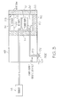
- the distributed electronics fuel control system 2 illustrated in FIG. 2 is a main fuel controller 66 having several thermoelectrically cooled powered components 64.
- a similar afterburner fuel controller 76 is used for the afterburner 34 to supply fuel to the thrust augmentation fuel injectors 39.
- Pressurized fuel is supplied from a pressurized fuel source 72 to the main fuel controller 66 and the afterburner fuel controller 76.
- the pressurized fuel is used for powering fan inlet guide vane and variable vane compressor actuators 68 and 70 that operate the variable fan inlet guide vanes 35 and variable stator vanes 60 in the high pressure compressor 16, respectively.
- the main fuel controller 66 illustrated in FIG. 2 is an exemplary gas turbine engine control component with thermoelectrically cooled electronics.
- the main fuel controller 66 includes a few electronic devices such as main fuel metering valve 110 electronically connected to an integrated circuit (IC) 112 having a micro-processor 114.
- the integrated circuit is located inside an insulated compartment 116 of the main fuel controller 66 and exemplifies the thermoelectrically cooled electronics.
- the exemplary compartment 116 illustrated herein has insulation 67 located in walls 80 of the compartment 116.
- a thermoelectric cooler 118 is operably located in the compartment 116 for cooling the integrated circuit 112.
- the thermoelectric cooler 118 and/or the integrated circuit 112 are powered by a power supply 74 which in turn receives electrical power via an integrated power supply and bus cable 170.
- thermoelectric cooler 118 Electricity to power the thermoelectric cooler 118 and/or the integrated circuit 112 can also be brought in from an external source such as the FADEC via the integrated power supply and bus cable 170.
- the thermoelectric cooler 118 may be disposed in or on one of the walls 80 of the compartment 116.
- a heat sink 82 is operably connected to a hot side 84 of the thermoelectric cooler 118.
- the heat sink source illustrated herein is relatively cold fuel 42 and cold air may also be used as a heat sink source.
- a cold side 86 of the thermoelectric cooler 118 is exposed to an interior 88 of the compartment to cool the integrated circuit 112 and the micro-processor 114 of the integrated circuit if it has one.
- the cable 170 is connected to the integrated circuit 112 and has a bus connector 172 for connecting the cable to the bus 104.
- thermoelectric cooler 118 is very effective in cooling the integrated circuit 112 so that it can operate over a wide range of high engine temperatures, which may be caused by hot fuel, during the engine's operation during various operating conditions. This helps to insure the quality of its operation and where the supply of cooling fluid and temperature sinks available varies over the operating cycle of the engine.
- the thermoelectric cooler 118 provides an effective cooling system for the electronics in the components and reliable inexpensive cooling.
- the main fuel metering valve 110 has an electro-hydraulic servo-valve (EHSV) 120 for setting the position of the main fuel metering valve 110 and a position sensor indicated as a linear variable displacement transducer (LVDT) 122 for providing electronic position feedback of the main fuel metering valve 110 to the integrated circuit 112.
- EHSV electro-hydraulic servo-valve
- LVDT linear variable displacement transducer
- the integrated circuit 112 can serve various purposes and functions.
- the integrated circuit 112 can store calibration data about the EHSV, the main fuel metering valve 110, and or the LVDT.
- the integrated circuit 112 can also provide instructions for the operation of the EHSV and/or the main fuel metering valve 110.
- the integrated circuit 112 can take input from the EHSV, the main fuel metering valve 110, and or the LVDT and convert the data into digital information and send it to the electronic engine control 54 or FADEC along the controller area network via the bus 104.
- Other devices typically found in controllers include shutoff on/off valves 90 and transfer valves 92 and various other electro-hydraulic servo-valves (EHSV) 120.
- the shutoff on/off valves 90 and the transfer valves 92 include electrically powered solenoids 94, are electronically connected to the integrated circuit 112, and send and receive data and/or instructions to and from the FADEC over the bus to open and close.
- Real time analog sensor data is acquired using sensors using a sensing transducer, such as by measuring temperature with a resistive temperature measuring device 48 as is illustrated in FIG. 3. The same is done for any physical transducer such as pressure transducers 46, an exemplary location of which is illustrated in FIG. 1.
- Electronics in the sensor component autonomously convert the analog signals or data into digital signals or data in an integrated circuit 112. Once the analog data is converted to digital data, the digital data is routed across a network 102, such as a controller area network (CAN) via a bus 104 to, for example, the FADEC or perhaps to another component such as the fuel control system 2.
- a network 102 such as a controller area network (CAN) via a bus 104 to, for example, the FADEC or perhaps to another component such as the fuel control system 2.
- CAN controller area network
- FIG. 4 Schematically illustrated in FIG. 4 is the distributed electronics network 102 having various engine control components 4 having thermoelectrically cooled electronics.
- Current engine control systems incorporate analog input and output signals wired directly to the electronic engine control 54 or FADEC.
- the fuel control system 2 with distributed electronics having engine control components includes sensors with thermoelectrically cooled electronics such as shaft speed sensors and pressure and temperature sensors.
- Other components in the network 102 with thermoelectrically cooled electronics include a main fuel controller 66 and an afterburner fuel controller 76 (illustrated in FIG. 1) having main and AB (afterburner) fuel control flow position sensors, respectively, which are illustrated herein as linear variable displacement transducers (LVDTs) 122.
- the fan inlet guide vane and variable vane compressor actuators 68 and 70 (illustrated in FIG.
- thermoelectrically cooled electronics such as integrated circuits disclosed above. Calibration data stored in the electronics or integrated circuits of the sensors allow accurate compensation of the sensors based on temperature or other calibration parameters.
- Other components with thermoelectrically cooled electronics contemplated but not illustrated herein include air valves such as ones used active clearance control, bore core cooling, high pressure bleed valves, and flow control valves.
Landscapes
- Physics & Mathematics (AREA)
- Thermal Sciences (AREA)
- Engineering & Computer Science (AREA)
- Microelectronics & Electronic Packaging (AREA)
- Control Of Turbines (AREA)
- Turbine Rotor Nozzle Sealing (AREA)
Applications Claiming Priority (1)
| Application Number | Priority Date | Filing Date | Title |
|---|---|---|---|
| US11/520,214 US7779811B1 (en) | 2006-09-13 | 2006-09-13 | Thermoelectrically cooled components for distributed electronics control system for gas turbine engines |
Publications (3)
| Publication Number | Publication Date |
|---|---|
| EP1905986A2 true EP1905986A2 (fr) | 2008-04-02 |
| EP1905986A3 EP1905986A3 (fr) | 2011-06-15 |
| EP1905986B1 EP1905986B1 (fr) | 2017-03-15 |
Family
ID=38818823
Family Applications (1)
| Application Number | Title | Priority Date | Filing Date |
|---|---|---|---|
| EP07115633.5A Ceased EP1905986B1 (fr) | 2006-09-13 | 2007-09-04 | Composants refroidis thermoélectriquement pour système de contrôle à électronique pour turbines à gaz |
Country Status (4)
| Country | Link |
|---|---|
| US (1) | US7779811B1 (fr) |
| EP (1) | EP1905986B1 (fr) |
| JP (1) | JP5134321B2 (fr) |
| CN (1) | CN101144429B (fr) |
Cited By (7)
| Publication number | Priority date | Publication date | Assignee | Title |
|---|---|---|---|---|
| US7779811B1 (en) * | 2006-09-13 | 2010-08-24 | General Electric Company | Thermoelectrically cooled components for distributed electronics control system for gas turbine engines |
| EP2147860A3 (fr) * | 2008-07-21 | 2013-03-06 | Hamilton Sundstrand Corporation | Ensemble échangeur thermique pour contrôle d'avion |
| EP2942508A1 (fr) * | 2014-05-08 | 2015-11-11 | Rolls-Royce North American Technologies, Inc. | Disponibilité de dissipateur de chaleur améliorée sur des moteurs à turbine à gaz grâce à l'utilisation de pompes à chaleur à l'état solide |
| EP3043046A1 (fr) * | 2015-01-12 | 2016-07-13 | Hamilton Sundstrand Corporation | Agencement de refroidissement de contrôleur |
| EP2469039A3 (fr) * | 2010-12-23 | 2017-12-27 | General Electric Company | Procédé de surveillance des paramètres de performance d'un moteur à turbine à gaz |
| EP3633152A1 (fr) * | 2018-10-01 | 2020-04-08 | United Technologies Corporation | Turboréacteur à double flux comportant une aube directrice d'entrée rotative motorisée |
| EP3901438A1 (fr) * | 2020-04-23 | 2021-10-27 | Rolls-Royce plc | Enceinte électronique pour moteur à turbine à gaz |
Families Citing this family (34)
| Publication number | Priority date | Publication date | Assignee | Title |
|---|---|---|---|---|
| WO2008045082A1 (fr) * | 2006-10-12 | 2008-04-17 | United Technologies Corporation | Réduction de longueur de piste nécessaire au décollage au moyen d'une tuyère variable |
| US8127555B2 (en) * | 2007-12-13 | 2012-03-06 | Pratt & Whitney Rocketdyne, Inc. | Flowpath heat exchanger for thermal management and power generation within a hypersonic vehicle |
| US20100242492A1 (en) * | 2009-03-30 | 2010-09-30 | Honeywell International Inc. | Distributed engine control systems and gas turbine engines |
| US20120095663A1 (en) * | 2010-10-14 | 2012-04-19 | Hamilton Sundstrand Corporation | Fmu mounted eec for small aircraft engine applications |
| US20120095662A1 (en) * | 2010-10-14 | 2012-04-19 | Hamilton Sundstrand Corporation | Electronic engine control software reconfiguration for distributed eec operation |
| CN102732853B (zh) * | 2011-04-08 | 2014-12-17 | 北京北方微电子基地设备工艺研究中心有限责任公司 | 腔室装置和具有它的基片处理设备 |
| US20130092350A1 (en) * | 2011-10-14 | 2013-04-18 | General Electric Company | System for cooling fluid flow within an engine |
| US8800594B2 (en) | 2012-02-02 | 2014-08-12 | Honeywell International Inc. | Gas turbine engine fuel return valve and system |
| US8490404B1 (en) * | 2012-02-28 | 2013-07-23 | General Electric Company | Sensor-based performance-seeking gas turbine engine control |
| US9399955B2 (en) | 2012-02-29 | 2016-07-26 | General Electric Company | Method and apparatus for local loop closure |
| FR2988978B1 (fr) * | 2012-03-28 | 2014-06-27 | Safran | Support boitier fadec en materiau composite |
| US9388744B2 (en) * | 2012-03-30 | 2016-07-12 | General Electric Company | Distributed gas turbine engine control system with remote interface units |
| FR2989734B1 (fr) * | 2012-04-24 | 2014-04-18 | Snecma | Turboreacteur incorporant des generateurs thermoelectriques |
| US20130305728A1 (en) * | 2012-05-15 | 2013-11-21 | General Electric Company | Systems and Methods for Minimizing Coking in Gas Turbine Engines |
| US9157366B2 (en) | 2012-05-30 | 2015-10-13 | United Technologies Corporation | Adaptive fan with cold turbine |
| US9018511B2 (en) | 2013-03-08 | 2015-04-28 | Hamilton Sundstrand Space Systems International, Inc. | Spring-loaded heat exchanger fins |
| US9488101B2 (en) | 2013-03-14 | 2016-11-08 | United Technologies Corporation | Adaptive fan reverse core geared turbofan engine with separate cold turbine |
| US9850822B2 (en) | 2013-03-15 | 2017-12-26 | United Technologies Corporation | Shroudless adaptive fan with free turbine |
| US9382011B2 (en) * | 2014-04-10 | 2016-07-05 | Pratt & Whitney Canada Corp. | Multiple aircraft engine control system and method of communicating data therein |
| US9914545B2 (en) | 2015-07-24 | 2018-03-13 | Hamilton Sundstrand Corporation | Aircraft heat exchange system including a thermoelectric device |
| US10225950B2 (en) | 2015-07-24 | 2019-03-05 | Hamilton Sundstrand Corporation | Aircraft heat exchange system including a thermoelectric device |
| US20170058693A1 (en) * | 2015-08-31 | 2017-03-02 | United Technologies Corporation | Cooled Information Node |
| US20170137141A1 (en) * | 2015-11-12 | 2017-05-18 | Hamilton Sundstrand Corporation | Automated control using simulated signals |
| US10208641B2 (en) * | 2015-11-25 | 2019-02-19 | The Boeing Company | Thermal electric assembly attached on an outer surface of a hot section of a gas turbine engine to generate electrical power |
| US20170159563A1 (en) * | 2015-12-07 | 2017-06-08 | General Electric Company | Method and system for pre-cooler exhaust energy recovery |
| US20170219118A1 (en) * | 2016-01-28 | 2017-08-03 | Hamilton Sundstrand Corporation | Bleed valve position sensor |
| US11105265B2 (en) * | 2016-09-02 | 2021-08-31 | Raytheon Technologies Corporation | Supplemental cooling air for turbine exhaust components and surfaces |
| US10099796B2 (en) | 2016-10-04 | 2018-10-16 | General Electric Company | System and method for dynamically controlling the operation of an aircraft |
| US20190218972A1 (en) * | 2018-01-18 | 2019-07-18 | General Electric Company | Thermally protected thermoplastic duct and assembly |
| US11174789B2 (en) * | 2018-05-23 | 2021-11-16 | General Electric Company | Air cycle assembly for a gas turbine engine assembly |
| US11236683B2 (en) * | 2018-06-20 | 2022-02-01 | Rolls-Royce Plc | Control system |
| CN110657044B (zh) * | 2019-08-30 | 2020-09-25 | 中国科学院工程热物理研究所 | 一种电驱式加力燃烧室与可调面积尾喷管一体化结构 |
| US11958622B2 (en) * | 2020-05-15 | 2024-04-16 | Pratt & Whitney Canada Corp. | Protection functions |
| US11492913B2 (en) * | 2020-07-21 | 2022-11-08 | General Electric Company | Cooling hole inspection system |
Family Cites Families (27)
| Publication number | Priority date | Publication date | Assignee | Title |
|---|---|---|---|---|
| US4773212A (en) | 1981-04-01 | 1988-09-27 | United Technologies Corporation | Balancing the heat flow between components associated with a gas turbine engine |
| US4608819A (en) * | 1983-12-27 | 1986-09-02 | General Electric Company | Gas turbine engine component cooling system |
| US4867574A (en) | 1988-05-19 | 1989-09-19 | Jenkofsky John J | Ultra high speed infrared temperature measuring device |
| US4935864A (en) * | 1989-06-20 | 1990-06-19 | Digital Equipment Corporation | Localized cooling apparatus for cooling integrated circuit devices |
| JPH05102358A (ja) * | 1991-10-09 | 1993-04-23 | Nec Corp | 集積回路の冷却構造 |
| US5487266A (en) * | 1992-05-05 | 1996-01-30 | General Electric Company | Combustion control for producing low NOx emissions through use of flame spectroscopy |
| EP1067282A2 (fr) * | 1993-03-03 | 2001-01-10 | KETEMA AEROSPACE & ELECTRONICS DIVISION | Système de commande integré pour une turbine à gaz |
| JP3560414B2 (ja) * | 1996-05-07 | 2004-09-02 | 北川工業株式会社 | ペルチェ素子 |
| US6586835B1 (en) | 1998-08-31 | 2003-07-01 | Micron Technology, Inc. | Compact system module with built-in thermoelectric cooling |
| US6102001A (en) | 1998-12-04 | 2000-08-15 | Woodward Governor Company | Variable displacement pump fuel metering system and electrohydraulic servo-valve for controlling the same |
| US6173576B1 (en) * | 1999-03-25 | 2001-01-16 | Intel Corporation | Cooling unit for an integrated circuit package |
| US6196002B1 (en) * | 1999-06-24 | 2001-03-06 | Advanced Micro Devices, Inc. | Ball grid array package having thermoelectric cooler |
| US6623250B2 (en) | 2000-02-17 | 2003-09-23 | Goodrich Pump And Engine Control Systems, Inc. | Fuel metering unit |
| US6481211B1 (en) * | 2000-11-06 | 2002-11-19 | Joel C. Haas | Turbine engine cycling thermo-mechanical stress control |
| US6959536B1 (en) | 2000-11-27 | 2005-11-01 | James Maher | Fuel pump metering system |
| US6839613B2 (en) * | 2001-07-17 | 2005-01-04 | General Electric Company | Remote tuning for gas turbines |
| EP1296046A3 (fr) | 2001-09-24 | 2004-07-14 | Goodrich Control Systems Limited | Commande éléctronique de moteur |
| GB0206220D0 (en) | 2002-03-15 | 2002-05-01 | Lucas Industries Ltd | Fuel system |
| WO2003098052A1 (fr) | 2002-05-16 | 2003-11-27 | Bell Helicopter Textron Inc. | Soupape integree a trois fonctions |
| DE10233836A1 (de) * | 2002-07-25 | 2004-02-05 | Robert Bosch Gmbh | Elektronikgehäuse |
| US6962485B2 (en) | 2003-04-14 | 2005-11-08 | Goodrich Pump And Engine Control Systems, Inc. | Constant bypass flow controller for a variable displacement pump |
| US7007452B1 (en) | 2003-06-13 | 2006-03-07 | Woodward Governor Company | Fuel system for a gas turbine engine |
| US6981359B2 (en) | 2003-06-16 | 2006-01-03 | Woodward Governor Company | Centrifugal pump fuel system and method for gas turbine engine |
| US20050049775A1 (en) | 2003-08-29 | 2005-03-03 | General Electric Company | Distributed engine control system and method |
| US7036302B2 (en) | 2004-03-15 | 2006-05-02 | General Electric Company | Controlled pressure fuel nozzle system |
| JP2006063975A (ja) * | 2004-07-28 | 2006-03-09 | Honda Motor Co Ltd | ガスタービンエンジンのセンサ出力監視装置 |
| US7779811B1 (en) * | 2006-09-13 | 2010-08-24 | General Electric Company | Thermoelectrically cooled components for distributed electronics control system for gas turbine engines |
-
2006
- 2006-09-13 US US11/520,214 patent/US7779811B1/en active Active
-
2007
- 2007-09-04 EP EP07115633.5A patent/EP1905986B1/fr not_active Ceased
- 2007-09-12 JP JP2007236387A patent/JP5134321B2/ja not_active Expired - Fee Related
- 2007-09-13 CN CN200710154737.9A patent/CN101144429B/zh active Active
Cited By (10)
| Publication number | Priority date | Publication date | Assignee | Title |
|---|---|---|---|---|
| US7779811B1 (en) * | 2006-09-13 | 2010-08-24 | General Electric Company | Thermoelectrically cooled components for distributed electronics control system for gas turbine engines |
| EP2147860A3 (fr) * | 2008-07-21 | 2013-03-06 | Hamilton Sundstrand Corporation | Ensemble échangeur thermique pour contrôle d'avion |
| EP2469039A3 (fr) * | 2010-12-23 | 2017-12-27 | General Electric Company | Procédé de surveillance des paramètres de performance d'un moteur à turbine à gaz |
| EP2942508A1 (fr) * | 2014-05-08 | 2015-11-11 | Rolls-Royce North American Technologies, Inc. | Disponibilité de dissipateur de chaleur améliorée sur des moteurs à turbine à gaz grâce à l'utilisation de pompes à chaleur à l'état solide |
| US10443499B2 (en) | 2014-05-08 | 2019-10-15 | Rolls Royce North American Technologies, Inc. | Enhanced heat sink availability on gas turbine engines through the use of coolers |
| EP3043046A1 (fr) * | 2015-01-12 | 2016-07-13 | Hamilton Sundstrand Corporation | Agencement de refroidissement de contrôleur |
| US9850817B2 (en) | 2015-01-12 | 2017-12-26 | Hamilton Sundstrand Corporation | Controller cooling arrangement |
| EP3633152A1 (fr) * | 2018-10-01 | 2020-04-08 | United Technologies Corporation | Turboréacteur à double flux comportant une aube directrice d'entrée rotative motorisée |
| US10724395B2 (en) | 2018-10-01 | 2020-07-28 | Raytheon Technologies Corporation | Turbofan with motorized rotating inlet guide vane |
| EP3901438A1 (fr) * | 2020-04-23 | 2021-10-27 | Rolls-Royce plc | Enceinte électronique pour moteur à turbine à gaz |
Also Published As
| Publication number | Publication date |
|---|---|
| JP5134321B2 (ja) | 2013-01-30 |
| CN101144429A (zh) | 2008-03-19 |
| JP2008069780A (ja) | 2008-03-27 |
| EP1905986B1 (fr) | 2017-03-15 |
| EP1905986A3 (fr) | 2011-06-15 |
| CN101144429B (zh) | 2013-06-19 |
| US20100223902A1 (en) | 2010-09-09 |
| US7779811B1 (en) | 2010-08-24 |
Similar Documents
| Publication | Publication Date | Title |
|---|---|---|
| EP1905986B1 (fr) | Composants refroidis thermoélectriquement pour système de contrôle à électronique pour turbines à gaz | |
| CN114991962B (zh) | 燃气涡轮发动机热管理 | |
| US20100242492A1 (en) | Distributed engine control systems and gas turbine engines | |
| US10794286B2 (en) | Method and system for modulated turbine cooling as a function of engine health | |
| EP0694120B1 (fr) | Systeme integre de regulation pour turbomoteur | |
| EP2809910B1 (fr) | Système d'air tampon de turbine à gaz | |
| US12410752B2 (en) | System and method of detecting an airflow fault condition | |
| EP2476883B1 (fr) | Module de soupape de purge avec rétroaction de position et gaine de refroidissement | |
| EP3594474B1 (fr) | Moteur à turbine à gaz à refroidissement de turbine variable actif | |
| CN107152340A (zh) | 用于检测管道系统失效的方法和系统 | |
| CN110475947B (zh) | 用于涡轮发动机的压力传感器组件 | |
| US11795872B2 (en) | Engine and secondary power unit integrated operation | |
| EP3358144A1 (fr) | Système de commande de jeu d'extrémité actif dépendant de l'évaluation de la poussée | |
| US11421877B2 (en) | Vibration control for a gas turbine engine | |
| US20200256252A1 (en) | Hydraulically Driven Local Pump | |
| EP4112909A1 (fr) | Turbine hybride électrique à section variable | |
| WO2017213816A1 (fr) | Système de distribution de carburant et procédé pour turbine à gaz | |
| US12196137B2 (en) | Gas turbine engine with electrically driven compressor | |
| EP3299791B1 (fr) | Moteur à turbine à gaz doté de diagnostic d'échangeur de chaleur | |
| US20200070081A1 (en) | Monitoring servo-valve filter elements | |
| EP3296548B1 (fr) | Échangeur de chaleur pour turbine à gaz monté dans un capot intermédiaire | |
| CN115853646A (zh) | 调节热传输总线压力的系统和方法 | |
| EP3034838B1 (fr) | Système et procédé pour commander une condition environnementale d'un composant électronique de moteur | |
| EP3786990B1 (fr) | Connecteur basé sur condensateur pour câble coaxial | |
| EP3795812B1 (fr) | Échangeur de chaleur de carter de diffuseur |
Legal Events
| Date | Code | Title | Description |
|---|---|---|---|
| PUAI | Public reference made under article 153(3) epc to a published international application that has entered the european phase |
Free format text: ORIGINAL CODE: 0009012 |
|
| AK | Designated contracting states |
Kind code of ref document: A2 Designated state(s): AT BE BG CH CY CZ DE DK EE ES FI FR GB GR HU IE IS IT LI LT LU LV MC MT NL PL PT RO SE SI SK TR |
|
| AX | Request for extension of the european patent |
Extension state: AL BA HR MK YU |
|
| PUAL | Search report despatched |
Free format text: ORIGINAL CODE: 0009013 |
|
| AK | Designated contracting states |
Kind code of ref document: A3 Designated state(s): AT BE BG CH CY CZ DE DK EE ES FI FR GB GR HU IE IS IT LI LT LU LV MC MT NL PL PT RO SE SI SK TR |
|
| AX | Request for extension of the european patent |
Extension state: AL BA HR MK RS |
|
| 17P | Request for examination filed |
Effective date: 20111215 |
|
| AKX | Designation fees paid |
Designated state(s): DE FR GB |
|
| GRAP | Despatch of communication of intention to grant a patent |
Free format text: ORIGINAL CODE: EPIDOSNIGR1 |
|
| INTG | Intention to grant announced |
Effective date: 20161104 |
|
| GRAS | Grant fee paid |
Free format text: ORIGINAL CODE: EPIDOSNIGR3 |
|
| GRAA | (expected) grant |
Free format text: ORIGINAL CODE: 0009210 |
|
| AK | Designated contracting states |
Kind code of ref document: B1 Designated state(s): DE FR GB |
|
| REG | Reference to a national code |
Ref country code: GB Ref legal event code: FG4D |
|
| REG | Reference to a national code |
Ref country code: DE Ref legal event code: R096 Ref document number: 602007050160 Country of ref document: DE |
|
| REG | Reference to a national code |
Ref country code: FR Ref legal event code: PLFP Year of fee payment: 11 |
|
| PGFP | Annual fee paid to national office [announced via postgrant information from national office to epo] |
Ref country code: FR Payment date: 20170925 Year of fee payment: 11 |
|
| REG | Reference to a national code |
Ref country code: DE Ref legal event code: R097 Ref document number: 602007050160 Country of ref document: DE |
|
| PLBE | No opposition filed within time limit |
Free format text: ORIGINAL CODE: 0009261 |
|
| STAA | Information on the status of an ep patent application or granted ep patent |
Free format text: STATUS: NO OPPOSITION FILED WITHIN TIME LIMIT |
|
| PGFP | Annual fee paid to national office [announced via postgrant information from national office to epo] |
Ref country code: DE Payment date: 20170927 Year of fee payment: 11 |
|
| 26N | No opposition filed |
Effective date: 20171218 |
|
| GBPC | Gb: european patent ceased through non-payment of renewal fee |
Effective date: 20170904 |
|
| PG25 | Lapsed in a contracting state [announced via postgrant information from national office to epo] |
Ref country code: GB Free format text: LAPSE BECAUSE OF NON-PAYMENT OF DUE FEES Effective date: 20170904 |
|
| REG | Reference to a national code |
Ref country code: DE Ref legal event code: R119 Ref document number: 602007050160 Country of ref document: DE |
|
| PG25 | Lapsed in a contracting state [announced via postgrant information from national office to epo] |
Ref country code: DE Free format text: LAPSE BECAUSE OF NON-PAYMENT OF DUE FEES Effective date: 20190402 |
|
| PG25 | Lapsed in a contracting state [announced via postgrant information from national office to epo] |
Ref country code: FR Free format text: LAPSE BECAUSE OF NON-PAYMENT OF DUE FEES Effective date: 20180930 |