EP1906019A2 - Clapet anti-retour pour pompes de dosage - Google Patents
Clapet anti-retour pour pompes de dosage Download PDFInfo
- Publication number
- EP1906019A2 EP1906019A2 EP07018249A EP07018249A EP1906019A2 EP 1906019 A2 EP1906019 A2 EP 1906019A2 EP 07018249 A EP07018249 A EP 07018249A EP 07018249 A EP07018249 A EP 07018249A EP 1906019 A2 EP1906019 A2 EP 1906019A2
- Authority
- EP
- European Patent Office
- Prior art keywords
- valve body
- valve
- passage opening
- check valve
- pressure
- Prior art date
- Legal status (The legal status is an assumption and is not a legal conclusion. Google has not performed a legal analysis and makes no representation as to the accuracy of the status listed.)
- Withdrawn
Links
Images

Classifications
-
- F—MECHANICAL ENGINEERING; LIGHTING; HEATING; WEAPONS; BLASTING
- F04—POSITIVE - DISPLACEMENT MACHINES FOR LIQUIDS; PUMPS FOR LIQUIDS OR ELASTIC FLUIDS
- F04B—POSITIVE-DISPLACEMENT MACHINES FOR LIQUIDS; PUMPS
- F04B53/00—Component parts, details or accessories not provided for in, or of interest apart from, groups F04B1/00 - F04B23/00 or F04B39/00 - F04B47/00
- F04B53/10—Valves; Arrangement of valves
-
- B—PERFORMING OPERATIONS; TRANSPORTING
- B05—SPRAYING OR ATOMISING IN GENERAL; APPLYING FLUENT MATERIALS TO SURFACES, IN GENERAL
- B05B—SPRAYING APPARATUS; ATOMISING APPARATUS; NOZZLES
- B05B12/00—Arrangements for controlling delivery; Arrangements for controlling the spray area
- B05B12/14—Arrangements for controlling delivery; Arrangements for controlling the spray area for supplying a selected one of a plurality of liquids or other fluent materials or several in selected proportions to a spray apparatus, e.g. to a single spray outlet
- B05B12/1418—Arrangements for controlling delivery; Arrangements for controlling the spray area for supplying a selected one of a plurality of liquids or other fluent materials or several in selected proportions to a spray apparatus, e.g. to a single spray outlet for supplying several liquids or other fluent materials in selected proportions to a single spray outlet
-
- B—PERFORMING OPERATIONS; TRANSPORTING
- B05—SPRAYING OR ATOMISING IN GENERAL; APPLYING FLUENT MATERIALS TO SURFACES, IN GENERAL
- B05B—SPRAYING APPARATUS; ATOMISING APPARATUS; NOZZLES
- B05B7/00—Spraying apparatus for discharge of liquids or other fluent materials from two or more sources, e.g. of liquid and air, of powder and gas
- B05B7/24—Spraying apparatus for discharge of liquids or other fluent materials from two or more sources, e.g. of liquid and air, of powder and gas with means, e.g. a container, for supplying liquid or other fluent material to a discharge device
- B05B7/2486—Spraying apparatus for discharge of liquids or other fluent materials from two or more sources, e.g. of liquid and air, of powder and gas with means, e.g. a container, for supplying liquid or other fluent material to a discharge device with means for supplying liquid or other fluent material to several discharge devices
-
- B—PERFORMING OPERATIONS; TRANSPORTING
- B05—SPRAYING OR ATOMISING IN GENERAL; APPLYING FLUENT MATERIALS TO SURFACES, IN GENERAL
- B05B—SPRAYING APPARATUS; ATOMISING APPARATUS; NOZZLES
- B05B7/00—Spraying apparatus for discharge of liquids or other fluent materials from two or more sources, e.g. of liquid and air, of powder and gas
- B05B7/24—Spraying apparatus for discharge of liquids or other fluent materials from two or more sources, e.g. of liquid and air, of powder and gas with means, e.g. a container, for supplying liquid or other fluent material to a discharge device
- B05B7/26—Apparatus in which liquids or other fluent materials from different sources are brought together before entering the discharge device
- B05B7/28—Apparatus in which liquids or other fluent materials from different sources are brought together before entering the discharge device in which one liquid or other fluent material is fed or drawn through an orifice into a stream of a carrying fluid
- B05B7/32—Apparatus in which liquids or other fluent materials from different sources are brought together before entering the discharge device in which one liquid or other fluent material is fed or drawn through an orifice into a stream of a carrying fluid the fed liquid or other fluent material being under pressure
-
- F—MECHANICAL ENGINEERING; LIGHTING; HEATING; WEAPONS; BLASTING
- F04—POSITIVE - DISPLACEMENT MACHINES FOR LIQUIDS; PUMPS FOR LIQUIDS OR ELASTIC FLUIDS
- F04B—POSITIVE-DISPLACEMENT MACHINES FOR LIQUIDS; PUMPS
- F04B53/00—Component parts, details or accessories not provided for in, or of interest apart from, groups F04B1/00 - F04B23/00 or F04B39/00 - F04B47/00
- F04B53/10—Valves; Arrangement of valves
- F04B53/102—Disc valves
-
- F—MECHANICAL ENGINEERING; LIGHTING; HEATING; WEAPONS; BLASTING
- F04—POSITIVE - DISPLACEMENT MACHINES FOR LIQUIDS; PUMPS FOR LIQUIDS OR ELASTIC FLUIDS
- F04B—POSITIVE-DISPLACEMENT MACHINES FOR LIQUIDS; PUMPS
- F04B53/00—Component parts, details or accessories not provided for in, or of interest apart from, groups F04B1/00 - F04B23/00 or F04B39/00 - F04B47/00
- F04B53/10—Valves; Arrangement of valves
- F04B53/102—Disc valves
- F04B53/1022—Disc valves having means for guiding the closure member axially
Definitions
- the invention relates to a check valve for the metering pumps, in particular for use in spray devices of plant protection technology, with a valve housing, with a passage opening and a valve body which can assume at least one passage opening closing position and the passage opening releasing position, and means for applying a closing force on the valve body, wherein the closing force biases the valve body into its, the passage opening occluding position, wherein the valve body in its, the valve seat closing state separates a delivery pressure range from a counter-pressure region.
- a check valve for a metering pump, a metering pump and a spray device for the plant protection technology are provided, with which a very precise Wirkstoffstoffeindostechnik regardless of back pressure of a carrier liquid into which is to be metered, can be realized.
- a check valve for metering pumps in particular for use in spray devices of crop protection technology, with a valve housing having a passage opening and a valve body which can occupy at least one passage opening closing position and the passage opening releasing position, and means for applying a closing force on the valve body wherein the closing force biases the valve body into its position closing the passage opening, and wherein the valve body in its valve seat closing state separates a delivery pressure area from a counterpressure area, wherein the valve body is designed and arranged in the valve housing such that the passage opening closing position aligned parallel to the free cross section of the passage opening aligned effective engagement surface of the valve body for a back pressure in the counter-pressure region is substantially zero.
- valve body is always lifted counterpressure independent of the valve seat when the force exerted by the delivery pressure in the delivery pressure range on the valve body force is greater than the sum of the closing force on the valve body and a possible frictional force. It should be noted that at the moment in which the valve body has lifted from the valve seat, this equilibrium of forces no longer applies and the resulting during flow around the valve body dynamic forces can quite ensure that the valve body is lifted further from the valve seat.
- the non-return valve according to the invention can be arranged downstream of a metering pump in addition to intake and exhaust valves of a metering pump or can also be used as a pressure or outlet valve of the piston metering pump in order to eliminate the back pressure as influencing factor.
- valve body in its, the passage opening closing state traverses an outgoing from the passage opening conveyor channel and is guided displaceably in an outgoing from the conveyor channel bearing bore in the valve housing.
- a bearing bore aligned with its cross section parallel to the free cross section of the passage opening thus opposes the sealing surface of the valve body in the position of the valve body which closes the passage opening and is designed such that the counterpressure does not have access to the rear side of the valve body. Since the bearing bore exactly the same area as the sealing surface of the valve seat has, the effective engagement surface of the back pressure on the valve body in the passage opening closing position equal to zero.
- the delivery channel in the counter-pressure region and a slidably disposed in the bearing bore portion of the valve body is sealed at least in the region of its, the conveying channel facing away from the back pressure area.
- the back, or a space of the bearing bore, which limits the back of the valve body, can then be vented, for example against the environment.
- the back of the valve body must not be accessible for back pressure. If, for example, a valve spring is located in the space of the bearing bore on the rear side of the valve body, this space must be vented to the environment.
- a free area of the passage opening corresponds to a cross-sectional area of the section of the valve body which is displaceably guided in the bearing bore.
- the attack surface for the back pressure is thus zero and the check valve according to the invention can work completely counterpressure independent.
- the free surface of the passage opening corresponds to the engagement surface for the opening pressure, which is also defined by the lying within the annular sealing surface of the valve seat area.
- the means for applying a closing force to the valve body cooperate with a rear side of the valve body facing away from the conveyor channel.
- the means for applying a closing force on the valve body on a spring, pneumatic means and / or hydraulic means.
- a space of the bearing bore which limits the back of the valve body, be vented against the environment and in addition to the ambient pressure, a spring may then be provided which presses the valve body in the direction of the valve seat surrounding the passage opening.
- the space bounded by the rear of the valve body may be selectively applied with a controlled air pressure or hydraulic pressure to produce a closing force.
- a pneumatic pressure it is for example also very easy to completely lock the check valve, so that no longer opens the check valve regardless of the pressure in the delivery chamber.
- the check valve forcibly opened and thus unlocked, for example, when the delivery chamber is to be flowed through freely, for example, in a rinsing operation.
- valve housing is cylindrical and formed in a Dosierpumpengephaseouse inserted. Conveniently, the valve housing is then sealed by means of circumferential sealing rings against the Dosierpumpengephaseuse.
- an unlocking device for unlocking the check valve is provided.
- Unlocking the check valve so opening the port regardless of the applied delivery pressure, may be appropriate to be able to rinse, for example, the check valve or to pump through active substances in a prefeed or recirculation mode through the check valve and the associated metering pump.
- An unlocking can, as already stated, be realized pneumatically by the valve body is lifted by means of negative pressure of the valve seat, or can be realized mechanically by means of a plunger.
- the valve body or the plunger for example, can also be moved electromagnetically.
- a metering pump with a check valve according to the invention and by a spray device for plant protection technology, in particular a field sprayer, with at least one metering pump according to the invention, wherein the metering promotes active substance in a carrier liquid line, which is in flow communication with at least one spray nozzle ,
- FIG. 1 shows a check valve 10 with a valve housing 12, which has a defined by a valve seat 14 passage opening.
- the valve housing 12 is arranged in a metering pump housing 16 shown only in sections.
- the valve housing 12 is constructed in two parts and consists of a first, sleeve-shaped portion in which a valve body 18 is slidably mounted, and a second, annular portion having the passage opening and the valve seat 14.
- struts 20 of a cage-like portion of the valve housing 12 are provided.
- the annular valve housing component sits with the valve seat 14 and between the struts 20, the medium flowing through the passage opening can flow out and reach the further course of a delivery channel 22.
- the valve body 18 traverses the delivery channel 22 in its position closing the passage opening and is displaceably arranged in the bearing bore 21 of the valve housing 12 on the side of the delivery channel 22 opposite the valve seat 14.
- a coil spring 24 is arranged in the illustrated embodiment, which generates a closing force F x on the valve body 18 in the direction of the valve seat 14.
- the space of the bearing bore 21, in which the coil spring 24 is arranged, is ventilated in this embodiment by means of a ventilation opening 26 to the environment.
- a hydraulic or pneumatic conduit may be connected to this vent opening 26 to pressurize the back of the valve body 18 with a hydraulic or pneumatic pressure to thereby produce or affect the closing force urging the valve body 18 toward the valve seat 14.
- a negative pressure may be applied to the back of the valve body 18 and thereby lift the valve body 18 from the valve seat 14, for example, when the check valve 10 is to be unlocked for a rinsing operation.
- the valve body 18 is sealed in the bearing bore 21 by means of a circumferential sealing ring 28.
- the valve housing 12 is sealed by means of a plurality of sealing rings 30, 32 against the Dosierpumpengephase 16.
- the passage opening defined by the valve seat 14 separates a delivery pressure region 34 of the dosing pump from a counterpressure region 36.
- a delivery pressure P ö whose force effect on the valve body 18 is symbolized by means of an arrow 38.
- P G a backpressure P G , which on all sides acts according to the arrow 40 on the regions of the valve body 18 located in the delivery channel 22.
- the valve body 18 is lifted off the valve seat 14 and liquid can pass from the delivery pressure region 34 into the counter-pressure region 36.
- the independence of the back pressure is achieved in the illustrated embodiment, characterized in that the free cross-sectional area of the defined by the valve seat 14 passage opening when seated valve body 18 is exactly the same size as the cross-sectional area of the bearing bore 21 and in that the side facing away from the valve seat of the valve body 18 is shielded from the back pressure or sealed against it.
- the effective attack surface for the back pressure P G is then always zero.
- valve spring 14 exceeds the force resulting from the delivery pressure P ö and its engagement surface on the valve body 18 of the valve, the valve body 18 is again pressed onto the valve seat 14 and the passage opening is therefore closed.
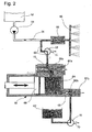
- FIG. 2 shows a spray device according to the invention for the crop protection technology with a metering pump 50, which is provided with a check valve 10 according to the invention as an outlet or pressure valve.
- the check valve 10 of the metering pump 50 thus operate independently of the back pressure, as was explained with reference to the check valve 10 of FIG.
- the metering pump 50 has as a suction valve 65 a pilot-operated check valve.
- carrier liquid container 52 with carrier liquid, especially water, from which, starting from a carrier liquid line 54 via a mixer 56 to a spray bar 58 is guided with a plurality of spray nozzles.
- the water is conveyed by a broth pump 51 to the spray nozzles.
- This broth pump 51 generates in a known manner the pressure required to atomize the spray mixture of water and dosed to the active ingredient at the nozzle.
- On a representation of the usual for the regulation of the injection pressure components has been omitted for clarity.
- an active ingredient feed line 60 which in turn is fed by the metering pump 50 with active ingredient.
- the metering pump 50 itself is supplied with active ingredient from an active substance storage tank 62.
- the metering pump 50 is designed as a piston pump. Upon movement of the piston in the representation of FIG. 2 to the left, a negative pressure is created in the delivery chamber 64 of the metering pump 50, so that active substance is sucked from the active substance storage container 62 through the intake valve 65 into the delivery chamber 64. If subsequently the piston 69 is moved to the right in the representation of FIG. 2, an overpressure is created in the delivery chamber 64 and since the check valve 65 blocks the flow connection to the active substance reservoir 62, active substance is forced out of the delivery chamber 64 through the check valve 10 into the active agent supply line 60. In the mixer 56 there is an intimate mixing of active substance and carrier liquid, so that a homogeneous mixture of carrier liquid and active substance can be sprayed on the spray bar 58.
- the metering pump 50 pumps the active ingredient into liquid pulses in the carrier liquid line 54, the back pressure-independent check valve 10 always opens independently of the back pressure in the carrier liquid line 54 and the active ingredient supply line 60 at exactly the same delivery pressure in the delivery chamber 64.
- the volume of active substance which is emitted to the right into the active substance supply line 60 with each movement of the piston 69 of the metering pump 50 in FIG. 2 is thus always exactly the same regardless of the backpressure. This is important, for example, because the carrier liquid flow leaving the nozzles at the spray bar 58 is dependent on the injection pressure.
- This injection pressure in the carrier liquid line 54 is usually regulated depending on the driving speed of the spray device, the carrier liquid flow and adjusted to per sprayed area always be able to apply the same amount of spray agent.
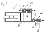
- each of the non-return valves 10, 65 is provided with an unlocking device in the form of a plunger 66a, 66b, which can be moved against the valve body by a piston 67a, 67b, for example, pneumatically actuated.
- a plunger 66a, 66b and the piston 67a, 67b By means of the plunger 66a, 66b and the piston 67a, 67b, the valve body of the check valves 10, 65 are mechanically lifted from the respective associated valve seat, so that a respective passage opening is then always open regardless of the pressure conditions.
- Such an unlocking position of the check valves 10, 65 is shown in the schematic representation of FIG. 3 and can be used to pump liquid through the delivery chamber 64 of the metering pump 50, and regardless of the direction.
- compressed air can be fed in through a valve 68 via a compressed-air connection 72 shown in dashed lines in FIG. 3 in order to push active substance from the delivery chamber 64 counter to the actual conveying direction into the active substance storage container 62.
- rinsing liquid can then be introduced via a valve 70 and a rinsing liquid connection 74 shown in dashed lines in FIG. 3 in order to rinse the delivery chamber 64 and the check valves 10, 65 and completely clean them of any remaining active substance.
Landscapes
- Engineering & Computer Science (AREA)
- Mechanical Engineering (AREA)
- General Engineering & Computer Science (AREA)
- Check Valves (AREA)
- Details Of Reciprocating Pumps (AREA)
Applications Claiming Priority (1)
| Application Number | Priority Date | Filing Date | Title |
|---|---|---|---|
| DE102006045448A DE102006045448A1 (de) | 2006-09-19 | 2006-09-19 | Rückschlagventil für Dosierpumpen, Dosierpumpe und Spritzvorrichtung für die Pflanzenschutztechnik |
Publications (2)
| Publication Number | Publication Date |
|---|---|
| EP1906019A2 true EP1906019A2 (fr) | 2008-04-02 |
| EP1906019A3 EP1906019A3 (fr) | 2009-10-28 |
Family
ID=38736024
Family Applications (1)
| Application Number | Title | Priority Date | Filing Date |
|---|---|---|---|
| EP07018249A Withdrawn EP1906019A3 (fr) | 2006-09-19 | 2007-09-18 | Clapet anti-retour pour pompes de dosage |
Country Status (2)
| Country | Link |
|---|---|
| EP (1) | EP1906019A3 (fr) |
| DE (1) | DE102006045448A1 (fr) |
Cited By (5)
| Publication number | Priority date | Publication date | Assignee | Title |
|---|---|---|---|---|
| WO2009153085A1 (fr) * | 2008-06-17 | 2009-12-23 | Robert Bosch Gmbh | Système de dosage d’un agent liquide, en particulier d’une solution eau-urée |
| CN103452831A (zh) * | 2013-08-20 | 2013-12-18 | 米顿罗工业设备(上海)有限公司 | 一种应用于计量泵中下沉式泵头的自动排气阀 |
| WO2014133712A1 (fr) * | 2013-02-28 | 2014-09-04 | Ingersoll-Rand Company | Pompe à déplacement direct avec étalonnage pour compensation de la pression |
| EP2611289B1 (fr) | 2010-08-31 | 2016-01-06 | Exel Industries | Ensemble de pulvérisation et pulvérisateur équipé d'au moins un tel ensemble |
| CN114060574A (zh) * | 2021-11-25 | 2022-02-18 | 蓝箭航天空间科技股份有限公司 | 一种单向阀、火箭发动机增压系统及火箭发动机 |
Family Cites Families (9)
| Publication number | Priority date | Publication date | Assignee | Title |
|---|---|---|---|---|
| DE1943693C3 (de) * | 1969-08-28 | 1981-07-16 | Robert Bosch Gmbh, 7000 Stuttgart | Federbelastetes Rückschlagventil |
| US3980230A (en) * | 1973-08-14 | 1976-09-14 | Pringle Orvi C | Sprayer-mixer |
| DE2831697A1 (de) * | 1978-07-19 | 1980-01-31 | Friedrich Freimuth | Bruchgesichertes hydraulisch entsperrbares rueckschlagventil |
| DE4401074B4 (de) * | 1994-01-15 | 2007-01-18 | Robert Bosch Gmbh | Pumpenanordnung, insbesondere zur Förderung von Kraftstoff aus einem Vorratsbehälter zu einer Brennkraftmaschine |
| DE19902292A1 (de) * | 1999-01-21 | 2000-07-27 | Mannesmann Rexroth Ag | Fördereinheit |
| DE10014191B4 (de) * | 2000-03-24 | 2010-05-12 | Stein, Günter | Steuerventil |
| DE102004020275B4 (de) * | 2004-03-15 | 2006-04-27 | Brueninghaus Hydromatik Gmbh | Ventil |
| DE102004047585A1 (de) * | 2004-09-23 | 2006-03-30 | Lechler Gmbh | Wirkstoffversorgungssystem und Spritzeinrichtung zum Versprühen von Flüssigkeiten |
| DE202006000277U1 (de) * | 2006-01-09 | 2006-03-02 | Wiwa Wilhelm Wagner Gmbh & Co. Kg | Dosiereinrichtung zur Förderung eines fließfähigen Materials |
-
2006
- 2006-09-19 DE DE102006045448A patent/DE102006045448A1/de not_active Withdrawn
-
2007
- 2007-09-18 EP EP07018249A patent/EP1906019A3/fr not_active Withdrawn
Cited By (8)
| Publication number | Priority date | Publication date | Assignee | Title |
|---|---|---|---|---|
| WO2009153085A1 (fr) * | 2008-06-17 | 2009-12-23 | Robert Bosch Gmbh | Système de dosage d’un agent liquide, en particulier d’une solution eau-urée |
| EP2611289B1 (fr) | 2010-08-31 | 2016-01-06 | Exel Industries | Ensemble de pulvérisation et pulvérisateur équipé d'au moins un tel ensemble |
| US11779006B2 (en) | 2010-08-31 | 2023-10-10 | Exel Industries | Spraying assembly, and sprayer equipped with at least one such assembly |
| WO2014133712A1 (fr) * | 2013-02-28 | 2014-09-04 | Ingersoll-Rand Company | Pompe à déplacement direct avec étalonnage pour compensation de la pression |
| US10036378B2 (en) | 2013-02-28 | 2018-07-31 | Ingersoll-Rand Company | Positive displacement pump with pressure compensating calibration |
| CN103452831A (zh) * | 2013-08-20 | 2013-12-18 | 米顿罗工业设备(上海)有限公司 | 一种应用于计量泵中下沉式泵头的自动排气阀 |
| CN103452831B (zh) * | 2013-08-20 | 2016-02-24 | 米顿罗工业设备(上海)有限公司 | 一种应用于计量泵中下沉式泵头的自动排气阀 |
| CN114060574A (zh) * | 2021-11-25 | 2022-02-18 | 蓝箭航天空间科技股份有限公司 | 一种单向阀、火箭发动机增压系统及火箭发动机 |
Also Published As
| Publication number | Publication date |
|---|---|
| EP1906019A3 (fr) | 2009-10-28 |
| DE102006045448A1 (de) | 2008-03-27 |
Similar Documents
| Publication | Publication Date | Title |
|---|---|---|
| DE3908963C2 (de) | Gerät zum Applizieren von Pflanzenbehandlungsmitteln unter geschwindigkeitsabhängiger Direkteinspeisung | |
| EP1906013A2 (fr) | Pompe de dosage, dispositif de pulvérisation pour la pulvérisation de moyens de pulvérisation tout comme procédé de fonctionnement d'un tel dispositif de pulvérisation | |
| DE102012218903B4 (de) | Hydraulische Ventilanordnung und hydraulische Maschinenanordnung mit einer derartigen Ventilanordnung | |
| EP3645885B1 (fr) | Appareil de nettoyage à haute pression | |
| DE3248622C2 (de) | Hochdruckreinigungsgerät | |
| DE102017220028A1 (de) | Spritzeinrichtung und Verfahren | |
| DE102013205895A1 (de) | Pulverdichtstrompumpe zum Fördern von Beschichtungspulver sowie entsprechendes Verfahren | |
| EP1906019A2 (fr) | Clapet anti-retour pour pompes de dosage | |
| EP1691601A2 (fr) | Dispositif de pulverisation de liquides et porte-buses | |
| DE2746037C3 (de) | Hochdruckreinigungsgerät | |
| DE10235140B4 (de) | Kolbenpumpe | |
| DE2736597A1 (de) | Elektromagnetische pumpe | |
| DE20114393U1 (de) | Vorrichtung zur Aufbringung von versprühbaren Flüssigkeiten | |
| EP1320415B1 (fr) | Dispositif pour l'application de liquides a pulveriser | |
| DE3922956C2 (fr) | ||
| DE10161438A1 (de) | Hubkolbenmaschine | |
| EP3861416B1 (fr) | Système d'éjection de liquide pour une installation de lavage de véhicules et son procédé de fonctionnement | |
| DE2045997B2 (de) | Fluessigkeitskolbenpumpe zur uebertragung hydraulischer druckimpulse oder eines pulsierenden fluessigkeitsstrahles auf ein handgeraet zur koerperpflege | |
| EP3508280B1 (fr) | Dispositif de distribution permettant de distribuer des milieux liquides | |
| CH616235A5 (en) | Device for testing fuel injection valves. | |
| DE10312738B4 (de) | Einspritzventil mit hydraulisch betätigter Nadel und Hohlnadel und Verfahren zum Steuern einer Einspritzung | |
| EP0627268A2 (fr) | Dispositif de pulvérisation de liquide, en particulier pour les machines à imprimer | |
| EP0078516A1 (fr) | Dispositif de pompage pour l'alimentation simultanée d'un dispositif pulvérisateur en au moins deux liquides à atomiser en proportion à choisir | |
| DE19927070B4 (de) | Hydraulische Presse | |
| DE3316919A1 (de) | Vorrichtung zum dosierten einspeisen von konzentrat in eine verduennungsfluessigkeit |
Legal Events
| Date | Code | Title | Description |
|---|---|---|---|
| PUAI | Public reference made under article 153(3) epc to a published international application that has entered the european phase |
Free format text: ORIGINAL CODE: 0009012 |
|
| AK | Designated contracting states |
Kind code of ref document: A2 Designated state(s): AT BE BG CH CY CZ DE DK EE ES FI FR GB GR HU IE IS IT LI LT LU LV MC MT NL PL PT RO SE SI SK TR |
|
| AX | Request for extension of the european patent |
Extension state: AL BA HR MK YU |
|
| PUAL | Search report despatched |
Free format text: ORIGINAL CODE: 0009013 |
|
| AK | Designated contracting states |
Kind code of ref document: A3 Designated state(s): AT BE BG CH CY CZ DE DK EE ES FI FR GB GR HU IE IS IT LI LT LU LV MC MT NL PL PT RO SE SI SK TR |
|
| AX | Request for extension of the european patent |
Extension state: AL BA HR MK RS |
|
| RIC1 | Information provided on ipc code assigned before grant |
Ipc: B05B 7/32 20060101ALI20090922BHEP Ipc: F04B 53/10 20060101ALI20090922BHEP Ipc: F16K 15/02 20060101AFI20090922BHEP |
|
| AKX | Designation fees paid | ||
| STAA | Information on the status of an ep patent application or granted ep patent |
Free format text: STATUS: THE APPLICATION IS DEEMED TO BE WITHDRAWN |
|
| 18D | Application deemed to be withdrawn |
Effective date: 20100429 |
|
| REG | Reference to a national code |
Ref country code: DE Ref legal event code: 8566 |