EP1906030A2 - Drucksteuerungsvorrichtung für Baumaschinen - Google Patents
Drucksteuerungsvorrichtung für Baumaschinen Download PDFInfo
- Publication number
- EP1906030A2 EP1906030A2 EP20070014737 EP07014737A EP1906030A2 EP 1906030 A2 EP1906030 A2 EP 1906030A2 EP 20070014737 EP20070014737 EP 20070014737 EP 07014737 A EP07014737 A EP 07014737A EP 1906030 A2 EP1906030 A2 EP 1906030A2
- Authority
- EP
- European Patent Office
- Prior art keywords
- pressure
- port
- spool
- output port
- input port
- Prior art date
- Legal status (The legal status is an assumption and is not a legal conclusion. Google has not performed a legal analysis and makes no representation as to the accuracy of the status listed.)
- Withdrawn
Links
- 239000012530 fluid Substances 0.000 claims abstract description 12
- 230000003247 decreasing effect Effects 0.000 description 3
- 238000010276 construction Methods 0.000 description 2
- 238000007792 addition Methods 0.000 description 1
- 238000010586 diagram Methods 0.000 description 1
- 230000004048 modification Effects 0.000 description 1
- 238000012986 modification Methods 0.000 description 1
- 238000006467 substitution reaction Methods 0.000 description 1
Images


Classifications
-
- F—MECHANICAL ENGINEERING; LIGHTING; HEATING; WEAPONS; BLASTING
- F15—FLUID-PRESSURE ACTUATORS; HYDRAULICS OR PNEUMATICS IN GENERAL
- F15B—SYSTEMS ACTING BY MEANS OF FLUIDS IN GENERAL; FLUID-PRESSURE ACTUATORS, e.g. SERVOMOTORS; DETAILS OF FLUID-PRESSURE SYSTEMS, NOT OTHERWISE PROVIDED FOR
- F15B13/00—Details of servomotor systems ; Valves for servomotor systems
- F15B13/02—Fluid distribution or supply devices characterised by their adaptation to the control of servomotors
- F15B13/04—Fluid distribution or supply devices characterised by their adaptation to the control of servomotors for use with a single servomotor
- F15B13/0401—Valve members; Fluid interconnections therefor
- F15B13/0402—Valve members; Fluid interconnections therefor for linearly sliding valves, e.g. spool valves
-
- F—MECHANICAL ENGINEERING; LIGHTING; HEATING; WEAPONS; BLASTING
- F15—FLUID-PRESSURE ACTUATORS; HYDRAULICS OR PNEUMATICS IN GENERAL
- F15B—SYSTEMS ACTING BY MEANS OF FLUIDS IN GENERAL; FLUID-PRESSURE ACTUATORS, e.g. SERVOMOTORS; DETAILS OF FLUID-PRESSURE SYSTEMS, NOT OTHERWISE PROVIDED FOR
- F15B11/00—Servomotor systems without provision for follow-up action; Circuits therefor
-
- E—FIXED CONSTRUCTIONS
- E02—HYDRAULIC ENGINEERING; FOUNDATIONS; SOIL SHIFTING
- E02F—DREDGING; SOIL-SHIFTING
- E02F9/00—Component parts of dredgers or soil-shifting machines, not restricted to one of the kinds covered by groups E02F3/00 - E02F7/00
- E02F9/20—Drives; Control devices
-
- G—PHYSICS
- G05—CONTROLLING; REGULATING
- G05D—SYSTEMS FOR CONTROLLING OR REGULATING NON-ELECTRIC VARIABLES
- G05D16/00—Control of fluid pressure
- G05D16/04—Control of fluid pressure without auxiliary power
- G05D16/10—Control of fluid pressure without auxiliary power the sensing element being a piston or plunger
- G05D16/101—Control of fluid pressure without auxiliary power the sensing element being a piston or plunger the controller being arranged as a multiple-way valve
-
- G—PHYSICS
- G05—CONTROLLING; REGULATING
- G05D—SYSTEMS FOR CONTROLLING OR REGULATING NON-ELECTRIC VARIABLES
- G05D16/00—Control of fluid pressure
- G05D16/14—Control of fluid pressure with auxiliary non-electric power
- G05D16/18—Control of fluid pressure with auxiliary non-electric power derived from an external source
- G05D16/187—Control of fluid pressure with auxiliary non-electric power derived from an external source using pistons within the main valve
-
- Y—GENERAL TAGGING OF NEW TECHNOLOGICAL DEVELOPMENTS; GENERAL TAGGING OF CROSS-SECTIONAL TECHNOLOGIES SPANNING OVER SEVERAL SECTIONS OF THE IPC; TECHNICAL SUBJECTS COVERED BY FORMER USPC CROSS-REFERENCE ART COLLECTIONS [XRACs] AND DIGESTS
- Y10—TECHNICAL SUBJECTS COVERED BY FORMER USPC
- Y10T—TECHNICAL SUBJECTS COVERED BY FORMER US CLASSIFICATION
- Y10T137/00—Fluid handling
- Y10T137/8593—Systems
- Y10T137/86493—Multi-way valve unit
- Y10T137/86574—Supply and exhaust
- Y10T137/86582—Pilot-actuated
-
- Y—GENERAL TAGGING OF NEW TECHNOLOGICAL DEVELOPMENTS; GENERAL TAGGING OF CROSS-SECTIONAL TECHNOLOGIES SPANNING OVER SEVERAL SECTIONS OF THE IPC; TECHNICAL SUBJECTS COVERED BY FORMER USPC CROSS-REFERENCE ART COLLECTIONS [XRACs] AND DIGESTS
- Y10—TECHNICAL SUBJECTS COVERED BY FORMER USPC
- Y10T—TECHNICAL SUBJECTS COVERED BY FORMER US CLASSIFICATION
- Y10T137/00—Fluid handling
- Y10T137/8593—Systems
- Y10T137/86493—Multi-way valve unit
- Y10T137/86574—Supply and exhaust
- Y10T137/86622—Motor-operated
- Y10T137/8663—Fluid motor
-
- Y—GENERAL TAGGING OF NEW TECHNOLOGICAL DEVELOPMENTS; GENERAL TAGGING OF CROSS-SECTIONAL TECHNOLOGIES SPANNING OVER SEVERAL SECTIONS OF THE IPC; TECHNICAL SUBJECTS COVERED BY FORMER USPC CROSS-REFERENCE ART COLLECTIONS [XRACs] AND DIGESTS
- Y10—TECHNICAL SUBJECTS COVERED BY FORMER USPC
- Y10T—TECHNICAL SUBJECTS COVERED BY FORMER US CLASSIFICATION
- Y10T137/00—Fluid handling
- Y10T137/8593—Systems
- Y10T137/86493—Multi-way valve unit
- Y10T137/86574—Supply and exhaust
- Y10T137/8667—Reciprocating valve
- Y10T137/86694—Piston valve
- Y10T137/86702—With internal flow passage
Definitions
- the present invention relates to a pressure control device for heavy equipment which can distribute and supply hydraulic fluid fed from a hydraulic pump to a plurality of working devices having different load pressures, such as a boom and a bucket, in the case of simultaneously operating the working devices having different operating pressures using a single hydraulic pump.
- the present invention relates to a pressure control valve for heavy equipment which can smoothly operate a working device having a high load pressure by limiting a supply of hydraulic fluid to a working device having a low load pressure in the case of simultaneously operating a plurality of working devices in a hydraulic circuit in which a plurality of control valves (e.g., a boom control valve and a bucket control valve) are connected in parallel to a single hydraulic pump.
- a plurality of control valves e.g., a boom control valve and a bucket control valve
- the flow rate of hydraulic fluid being supplied from the hydraulic pump to the bucket having a low load pressure becomes lower than the flow rate of hydraulic fluid being supplied to the boom having a relatively high load pressure. Since this makes it impossible to operate the boom smoothly, the flow rate of the hydraulic fluid being supplied to the bucket is compulsorily adjusted.
- the present invention has been made to solve the above-mentioned problems occurring in the prior art while advantages achieved by the prior art are maintained intact.
- One object of the present invention is to provide a pressure control device for heavy equipment that can smoothly operate a plurality of working devices having different operating pressures in the case of simultaneously operating the working devices connected in parallel to a single hydraulic pump.
- a pressure control device for heavy equipment which includes a valve body having an input port, an output port, and a drain port, formed thereon; a spool, slidably installed in the valve body, for being shifted to connect the input port to the output port in response to a pressure obtained by adding an elastic force of a valve spring to a pressure being applied from the input port to a diaphragm of a first piston that is elastically supported in a first back chamber, and being shifted to disconnect the input port from the output port in response to a pressure being applied from the output port to a diaphragm of a second piston installed in a second back chamber; and a signal pressure port for applying a signal pressure to a diaphragm of the spool located in a third back chamber formed in the valve body, disconnecting the input port from the output port by shifting the spool in response to the pressure in the second back chamber and the signal pressure, and returning the pressure in the output
- the pressure control device for heavy equipment may further includes a first land part, formed on a periphery of the spool, for connecting the input port to the output port; a first passage, formed through the spool, for connecting the first land part to the first back chamber and supplying the hydraulic fluid fed from the input port to the first back chamber; a second land part, formed on the periphery of the spool, for connecting to the drain port; and a second passage for supplying the hydraulic fluid fed from the input port to the second back chamber, and connecting the output port to the drain port when the spool is shifted.
- a pressure control device for heavy equipment which includes a valve body having an input port, an output port, and a drain port, formed thereon; a spool, slidably installed in the valve body, for being shifted to connect the input port to the output port in response to a pressure obtained by adding an elastic force of a valve spring to a pressure being applied from the input port to a diaphragm of a first piston that is elastically supported in a first back chamber, and being shifted to disconnect the input port from the output port in response to a pressure being applied from the output port to a diaphragm located on an outer surface of the spool; and a signal pressure port for applying a signal pressure to a diaphragm of the spool located in a third back chamber formed on the valve body, disconnecting the input port from the output port by shifting the spool in response to a pressure acting upon the diaphragm located on the outer surface of the s
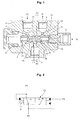
- a pressure control device for heavy equipment includes a valve body 5 having an input port 1, an output port 2, and a drain port 3, formed thereon; a spool 13, slidably installed in the valve body 5, for being shifted to connect the input port 1 to the output port 2 in response to a pressure obtained by adding an elastic force of a valve spring 9 to a pressure P1 being applied from the input port 1 to a diaphragm D1 of a first piston 7 that is elastically supported in a first back chamber 6, and being shifted to disconnect the input port 1 from the output port 2 in response to a pressure P2 being applied from the output port 2 to a diaphragm D2 of a second piston 11 installed in a second back chamber 10; and a signal pressure port 4 for applying a signal pressure P3 to a diaphragm D3 of the spool 13 located in a third back chamber 14 formed on the valve body 5, disconnecting the input port 1 from the output port 2 by shifting the s
- the pressure control device for heavy equipment may further includes a first ring-shaped land part 15, formed on a periphery of the spool 13, for connecting the input port 1 to the output port 2; a first passage 16, formed through the spool 13, for connecting the first land part 15 to the first back chamber 6 and supplying the hydraulic fluid fed from the input port 1 to the first back chamber 6, a second ring-shaped land part 17, formed on the periphery of the spool 13, for connecting to the drain port 3; and a second passage 18 for supplying the hydraulic fluid fed from the input port 1 to the second back chamber 10, and connecting the output port 2 to the drain port 3 when the spool 13 is shifted.
- the pressure P1 fed through the input port 1 is applied to the first back chamber 6 through the first land part 15 and the first passage 16.
- the pressure P2 in the output port 2 can be constantly controlled as the signal pressure P3 being applied to the signal pressure port 4, with respect to the pressure P1 of the input port 1.
- the spool 13 is kept pressed to the extent of "L1" in the right direction as shown in the drawing by the pressures P1 and P2 that are applied to the first and second back chambers 6 and 10, respectively, and thus the pressure P1 in the input port 1 becomes equal to the pressure P2 in the output port 2.
- the pressure P2 in the output port 2 is reduced, and the spool 13 is moved in the right direction as shown in the drawing.
- the pressure P1 in the input port 1 and the pressure P2 in the output port 2 are repeatedly intercepted from and connected to each other to keep the pressures in equilibrium.
- the pressure P1 in the input port 1 is increased or decreased in a state that the signal pressure P3 being applied to the third back chamber 14 is kept constant, the pressure P1 in the input port P1 is kept a reduced pressure P2 by the signal pressure P3 being applied to the spool 13. In this state, if the pressure P1 is further increased, the spool 13 is moved in the right direction as shown in the drawing.
- the pressure P1 in the input port 1 is increased or decreased in a state that the signal pressure P3 being applied to the third back chamber 14 is kept constant, the pressure P2 in the output port 2 is increased or decreased.
- a pressure control device for heavy equipment includes a valve body 5 having an input port 1, an output port 2, and a drain port 3, formed thereon; a spool 13a, slidably installed in the valve body 5, for being shifted to connect the input port 1 to the output port 2 in response to a pressure obtained by adding an elastic force of a valve spring 9 to a pressure being applied from the input port 1 to a diaphragm 8 of a first piston 7 that is elastically supported by the valve spring 9 in a first back chamber 6, and being shifted to disconnect the input port 1 from the output port 2 in response to a pressure being applied from the output port 2 to a diaphragm 20 located on an outer surface of the spool; and a signal pressure port 4 for applying a signal pressure to a diaphragm 19a of the spool 13a located in a third back chamber 14 formed on the valve body 5, disconnecting the input port 1 from the output port 2 by shifting the spool 13a in response to
- the spool 13a is shifted, corresponding to the signal pressure P3 applied from an outside to the third back chamber 14 through the signal pressure port 4, to control the operating pressure being applied from the input port 1 to the output port 2.
- the construction including the first piston 7 elastically supported in the first back chamber 6, the valve body 5 having the input port 1, the output port 2, and the drain port 3, and the third back chamber 14 to which the signal pressure P3 fed from the outside is applied through the signal pressure port 4, is substantially equal to that according to an embodiment of the present invention, the detailed description thereof will be omitted. Also, in the whole description of the present invention, the same drawing numerals are used for the same elements across various figures.
- the pressure control device for heavy equipment has the following advantages.
Landscapes
- Engineering & Computer Science (AREA)
- Physics & Mathematics (AREA)
- Fluid Mechanics (AREA)
- General Engineering & Computer Science (AREA)
- General Physics & Mathematics (AREA)
- Automation & Control Theory (AREA)
- Mechanical Engineering (AREA)
- Power Engineering (AREA)
- Structural Engineering (AREA)
- Civil Engineering (AREA)
- Mining & Mineral Resources (AREA)
- Control Of Fluid Pressure (AREA)
- Fluid-Pressure Circuits (AREA)
- Multiple-Way Valves (AREA)
- Operation Control Of Excavators (AREA)
Applications Claiming Priority (1)
| Application Number | Priority Date | Filing Date | Title |
|---|---|---|---|
| KR1020060094810A KR100780897B1 (ko) | 2006-09-28 | 2006-09-28 | 중장비용 압력 제어장치 |
Publications (2)
| Publication Number | Publication Date |
|---|---|
| EP1906030A2 true EP1906030A2 (de) | 2008-04-02 |
| EP1906030A3 EP1906030A3 (de) | 2013-12-18 |
Family
ID=38872079
Family Applications (1)
| Application Number | Title | Priority Date | Filing Date |
|---|---|---|---|
| EP20070014737 Withdrawn EP1906030A3 (de) | 2006-09-28 | 2007-07-27 | Drucksteuerungsvorrichtung für Baumaschinen |
Country Status (5)
| Country | Link |
|---|---|
| US (1) | US8011387B2 (de) |
| EP (1) | EP1906030A3 (de) |
| JP (1) | JP5150180B2 (de) |
| KR (1) | KR100780897B1 (de) |
| CN (1) | CN101153619B (de) |
Cited By (1)
| Publication number | Priority date | Publication date | Assignee | Title |
|---|---|---|---|---|
| ITPR20100026A1 (it) * | 2010-04-13 | 2011-10-14 | Walvoil Spa | Valvola idraulica di sequenza differenziale |
Families Citing this family (9)
| Publication number | Priority date | Publication date | Assignee | Title |
|---|---|---|---|---|
| US20110073192A1 (en) * | 2009-07-24 | 2011-03-31 | Hart David V | System and method for managing load flow requirements for a tractor single pump hydraulic system |
| KR101655458B1 (ko) * | 2009-12-24 | 2016-09-07 | 두산인프라코어 주식회사 | 건설기계의 유압펌프 제어용 밸브 |
| WO2012014006A1 (en) * | 2010-07-26 | 2012-02-02 | Hart, David, V. | System and method for managing load flow requirements for a tractor single pump hydraulic system |
| WO2012026633A1 (ko) * | 2010-08-24 | 2012-03-01 | 볼보 컨스트럭션 이큅먼트 에이비 | 건설기계의 제어장치 |
| US20140346379A1 (en) * | 2013-05-23 | 2014-11-27 | Hamilton Sundstrand Corporation | Backflow prevention valve |
| KR101991005B1 (ko) * | 2013-10-10 | 2019-06-21 | 현대코어모션 주식회사 | 건설장비용 변속장치 |
| KR101991003B1 (ko) * | 2013-10-10 | 2019-06-21 | 현대코어모션 주식회사 | 건설장비용 변속장치 |
| JP6043409B1 (ja) * | 2015-07-10 | 2016-12-14 | Kyb株式会社 | 棒状部材及びバルブ装置 |
| CN107605551B (zh) * | 2017-09-20 | 2023-08-01 | 中国船舶重工集团公司第七0三研究所 | 一种滑油压力屏蔽装置 |
Family Cites Families (16)
| Publication number | Priority date | Publication date | Assignee | Title |
|---|---|---|---|---|
| US3267965A (en) * | 1963-03-28 | 1966-08-23 | Airmatic Valve Inc | Pilot operated spool valve |
| DE3114437C2 (de) * | 1981-04-09 | 1989-10-12 | Mannesmann Rexroth GmbH, 8770 Lohr | Druckregelventil |
| JPS6217814A (ja) * | 1985-07-16 | 1987-01-26 | Daikin Ind Ltd | 3ポ−ト形減圧弁 |
| US4729408A (en) * | 1985-07-12 | 1988-03-08 | Caterpillar Inc. | Control system for independent control of fluid actuated devices |
| US5035312A (en) * | 1987-03-25 | 1991-07-30 | Kabushiki Kaisha Komatsu Seisakusho | Apparatus for controlling hydraulic pressure for clutch |
| JPS647970U (de) * | 1987-07-06 | 1989-01-17 | ||
| JPH01216104A (ja) * | 1987-11-02 | 1989-08-30 | Sumitomo Heavy Ind Ltd | 流量圧力制御弁 |
| JPH0615288Y2 (ja) * | 1988-01-29 | 1994-04-20 | 日産自動車株式会社 | 能動型サスペンション用圧力制御弁 |
| JP3183815B2 (ja) * | 1995-12-27 | 2001-07-09 | 日立建機株式会社 | 油圧ショベルの油圧回路 |
| JPH11201107A (ja) * | 1998-01-12 | 1999-07-27 | Hitachi Constr Mach Co Ltd | 圧力補償弁 |
| CN2379667Y (zh) * | 1998-12-04 | 2000-05-24 | 宜宾机电一体化研究所 | 一种两位式安全平衡阀 |
| KR20010009599A (ko) * | 1999-07-12 | 2001-02-05 | 양재신 | 로직밸브 |
| JP4371540B2 (ja) * | 2000-06-05 | 2009-11-25 | 本田技研工業株式会社 | スプール弁構造 |
| JP2004301190A (ja) * | 2003-03-28 | 2004-10-28 | Aisin Seiki Co Ltd | 油圧制御装置 |
| US7779853B2 (en) * | 2004-02-24 | 2010-08-24 | Parker-Hannifin Corporation | Proportional pressure control valve |
| KR100652871B1 (ko) * | 2004-02-24 | 2006-12-06 | 볼보 컨스트럭션 이키프먼트 홀딩 스웨덴 에이비 | 건설중장비용 유량제어장치 |
-
2006
- 2006-09-28 KR KR1020060094810A patent/KR100780897B1/ko not_active Expired - Fee Related
-
2007
- 2007-06-26 US US11/823,087 patent/US8011387B2/en not_active Expired - Fee Related
- 2007-07-26 CN CN2007101381142A patent/CN101153619B/zh not_active Expired - Fee Related
- 2007-07-27 EP EP20070014737 patent/EP1906030A3/de not_active Withdrawn
- 2007-09-19 JP JP2007241739A patent/JP5150180B2/ja not_active Expired - Fee Related
Non-Patent Citations (1)
| Title |
|---|
| None |
Cited By (2)
| Publication number | Priority date | Publication date | Assignee | Title |
|---|---|---|---|---|
| ITPR20100026A1 (it) * | 2010-04-13 | 2011-10-14 | Walvoil Spa | Valvola idraulica di sequenza differenziale |
| EP2378135A1 (de) * | 2010-04-13 | 2011-10-19 | Walvoil S.p.A. | Differentialhydraulisches Folgeventil |
Also Published As
| Publication number | Publication date |
|---|---|
| JP2008082549A (ja) | 2008-04-10 |
| US8011387B2 (en) | 2011-09-06 |
| US20080078285A1 (en) | 2008-04-03 |
| CN101153619B (zh) | 2012-07-04 |
| EP1906030A3 (de) | 2013-12-18 |
| JP5150180B2 (ja) | 2013-02-20 |
| KR100780897B1 (ko) | 2007-11-30 |
| CN101153619A (zh) | 2008-04-02 |
Similar Documents
| Publication | Publication Date | Title |
|---|---|---|
| EP1906030A2 (de) | Drucksteuerungsvorrichtung für Baumaschinen | |
| EP2048372A2 (de) | Doppelrückschlagventil mit Schwimmstellung | |
| EP1927759A1 (de) | Doppelrückschlagventil mit Schwimmfunktion | |
| US7581392B2 (en) | Straight traveling hydraulic circuit | |
| US8146482B2 (en) | Hydraulic circuit having holding valve of external pilot pressure operation type | |
| EP2644905A1 (de) | Durchflussregelventil für eine baumaschine | |
| CN106762909B (zh) | 一种高速开关阀先导控制的液压多路阀及其控制方法 | |
| EP2546421B1 (de) | Doppelrückschlagventil für baumaschinen | |
| US8818651B2 (en) | Flow control system for a hydraulic pump of construction machinery | |
| EP2256351A2 (de) | Hydrauliksystem mit verbessertem komplexen Betrieb | |
| EP3305994A2 (de) | Steuerungssystem für baumaschinen und steuerungsverfahren für baumaschinen | |
| CN101418823A (zh) | 用于重型设备的液压控制阀 | |
| EP1895059B1 (de) | Hydraulische Schaltung einer Optionsvorrichtung für einen Bagger | |
| CN107250563A (zh) | 用于建筑机械的流量控制阀 | |
| US3991571A (en) | Fluid system of a work vehicle having fluid combining means and signal combining means | |
| US10273987B2 (en) | Hydraulic valve arrangement with control/regulating function | |
| US4559965A (en) | Multiple compensating unloading valve circuit | |
| EP3282157A1 (de) | Steuerventil und flüssigkeitsdruckregelungsvorrichtung damit | |
| EP2005006B1 (de) | Vorgesteuerter druckkompensator mit verschiedenen bereichen und steuersystem zu seiner vorsteuerung | |
| US20150330058A1 (en) | Method for controlling hydraulic system for construction machine | |
| EP0774585A1 (de) | Druckompensierendes ventil | |
| JP4837528B2 (ja) | 油圧機器の油圧回路 | |
| US4308787A (en) | Priority flow divider | |
| JP5782483B2 (ja) | 油圧ユニット及び油圧システム | |
| JP2007249583A (ja) | 減圧弁 |
Legal Events
| Date | Code | Title | Description |
|---|---|---|---|
| PUAI | Public reference made under article 153(3) epc to a published international application that has entered the european phase |
Free format text: ORIGINAL CODE: 0009012 |
|
| AK | Designated contracting states |
Kind code of ref document: A2 Designated state(s): AT BE BG CH CY CZ DE DK EE ES FI FR GB GR HU IE IS IT LI LT LU LV MC MT NL PL PT RO SE SI SK TR |
|
| AX | Request for extension of the european patent |
Extension state: AL BA HR MK YU |
|
| RIN1 | Information on inventor provided before grant (corrected) |
Inventor name: CHEONG, HAE KYUN |
|
| PUAL | Search report despatched |
Free format text: ORIGINAL CODE: 0009013 |
|
| AK | Designated contracting states |
Kind code of ref document: A3 Designated state(s): AT BE BG CH CY CZ DE DK EE ES FI FR GB GR HU IE IS IT LI LT LU LV MC MT NL PL PT RO SE SI SK TR |
|
| AX | Request for extension of the european patent |
Extension state: AL BA HR MK RS |
|
| RIC1 | Information provided on ipc code assigned before grant |
Ipc: F15B 13/04 20060101AFI20131108BHEP Ipc: G05D 16/10 20060101ALI20131108BHEP |
|
| 17P | Request for examination filed |
Effective date: 20140618 |
|
| RBV | Designated contracting states (corrected) |
Designated state(s): AT BE BG CH CY CZ DE DK EE ES FI FR GB GR HU IE IS IT LI LT LU LV MC MT NL PL PT RO SE SI SK TR |
|
| AKX | Designation fees paid |
Designated state(s): DE FR GB IT |
|
| 17Q | First examination report despatched |
Effective date: 20170314 |
|
| STAA | Information on the status of an ep patent application or granted ep patent |
Free format text: STATUS: THE APPLICATION IS DEEMED TO BE WITHDRAWN |
|
| 18D | Application deemed to be withdrawn |
Effective date: 20170725 |