EP1906057A2 - Verfahren und Vorrichtung zur Übertragung von Wärme zum Automatikgetriebeöl unter Verwendung des Zufuhrstroms der Motorabgase - Google Patents
Verfahren und Vorrichtung zur Übertragung von Wärme zum Automatikgetriebeöl unter Verwendung des Zufuhrstroms der Motorabgase Download PDFInfo
- Publication number
- EP1906057A2 EP1906057A2 EP07018593A EP07018593A EP1906057A2 EP 1906057 A2 EP1906057 A2 EP 1906057A2 EP 07018593 A EP07018593 A EP 07018593A EP 07018593 A EP07018593 A EP 07018593A EP 1906057 A2 EP1906057 A2 EP 1906057A2
- Authority
- EP
- European Patent Office
- Prior art keywords
- exhaust gas
- transmission
- flow valve
- heat exchanger
- feed stream
- Prior art date
- Legal status (The legal status is an assumption and is not a legal conclusion. Google has not performed a legal analysis and makes no representation as to the accuracy of the status listed.)
- Granted
Links
Images

Classifications
-
- F—MECHANICAL ENGINEERING; LIGHTING; HEATING; WEAPONS; BLASTING
- F16—ENGINEERING ELEMENTS AND UNITS; GENERAL MEASURES FOR PRODUCING AND MAINTAINING EFFECTIVE FUNCTIONING OF MACHINES OR INSTALLATIONS; THERMAL INSULATION IN GENERAL
- F16H—GEARING
- F16H57/00—General details of gearing
- F16H57/04—Features relating to lubrication or cooling or heating
- F16H57/0412—Cooling or heating; Control of temperature
- F16H57/0413—Controlled cooling or heating of lubricant; Temperature control therefor
-
- F—MECHANICAL ENGINEERING; LIGHTING; HEATING; WEAPONS; BLASTING
- F01—MACHINES OR ENGINES IN GENERAL; ENGINE PLANTS IN GENERAL; STEAM ENGINES
- F01N—GAS-FLOW SILENCERS OR EXHAUST APPARATUS FOR MACHINES OR ENGINES IN GENERAL; GAS-FLOW SILENCERS OR EXHAUST APPARATUS FOR INTERNAL-COMBUSTION ENGINES
- F01N5/00—Exhaust or silencing apparatus combined or associated with devices profiting by exhaust energy
- F01N5/02—Exhaust or silencing apparatus combined or associated with devices profiting by exhaust energy the devices using heat
-
- F—MECHANICAL ENGINEERING; LIGHTING; HEATING; WEAPONS; BLASTING
- F02—COMBUSTION ENGINES; HOT-GAS OR COMBUSTION-PRODUCT ENGINE PLANTS
- F02M—SUPPLYING COMBUSTION ENGINES IN GENERAL WITH COMBUSTIBLE MIXTURES OR CONSTITUENTS THEREOF
- F02M26/00—Engine-pertinent apparatus for adding exhaust gases to combustion-air, main fuel or fuel-air mixture, e.g. by exhaust gas recirculation [EGR] systems
- F02M26/13—Arrangement or layout of EGR passages, e.g. in relation to specific engine parts or for incorporation of accessories
- F02M26/22—Arrangement or layout of EGR passages, e.g. in relation to specific engine parts or for incorporation of accessories with coolers in the recirculation passage
- F02M26/23—Layout, e.g. schematics
- F02M26/28—Layout, e.g. schematics with liquid-cooled heat exchangers
-
- F—MECHANICAL ENGINEERING; LIGHTING; HEATING; WEAPONS; BLASTING
- F16—ENGINEERING ELEMENTS AND UNITS; GENERAL MEASURES FOR PRODUCING AND MAINTAINING EFFECTIVE FUNCTIONING OF MACHINES OR INSTALLATIONS; THERMAL INSULATION IN GENERAL
- F16H—GEARING
- F16H57/00—General details of gearing
- F16H57/04—Features relating to lubrication or cooling or heating
- F16H57/0412—Cooling or heating; Control of temperature
- F16H57/0415—Air cooling or ventilation; Heat exchangers; Thermal insulations
-
- F—MECHANICAL ENGINEERING; LIGHTING; HEATING; WEAPONS; BLASTING
- F01—MACHINES OR ENGINES IN GENERAL; ENGINE PLANTS IN GENERAL; STEAM ENGINES
- F01N—GAS-FLOW SILENCERS OR EXHAUST APPARATUS FOR MACHINES OR ENGINES IN GENERAL; GAS-FLOW SILENCERS OR EXHAUST APPARATUS FOR INTERNAL-COMBUSTION ENGINES
- F01N2240/00—Combination or association of two or more different exhaust treating devices, or of at least one such device with an auxiliary device, not covered by indexing codes F01N2230/00 or F01N2250/00, one of the devices being
- F01N2240/02—Combination or association of two or more different exhaust treating devices, or of at least one such device with an auxiliary device, not covered by indexing codes F01N2230/00 or F01N2250/00, one of the devices being a heat exchanger
-
- F—MECHANICAL ENGINEERING; LIGHTING; HEATING; WEAPONS; BLASTING
- F01—MACHINES OR ENGINES IN GENERAL; ENGINE PLANTS IN GENERAL; STEAM ENGINES
- F01N—GAS-FLOW SILENCERS OR EXHAUST APPARATUS FOR MACHINES OR ENGINES IN GENERAL; GAS-FLOW SILENCERS OR EXHAUST APPARATUS FOR INTERNAL-COMBUSTION ENGINES
- F01N2410/00—By-passing, at least partially, exhaust from inlet to outlet of apparatus, to atmosphere or to other device
- F01N2410/02—By-passing, at least partially, exhaust from inlet to outlet of apparatus, to atmosphere or to other device in case of high temperature, e.g. overheating of catalytic reactor
-
- Y—GENERAL TAGGING OF NEW TECHNOLOGICAL DEVELOPMENTS; GENERAL TAGGING OF CROSS-SECTIONAL TECHNOLOGIES SPANNING OVER SEVERAL SECTIONS OF THE IPC; TECHNICAL SUBJECTS COVERED BY FORMER USPC CROSS-REFERENCE ART COLLECTIONS [XRACs] AND DIGESTS
- Y02—TECHNOLOGIES OR APPLICATIONS FOR MITIGATION OR ADAPTATION AGAINST CLIMATE CHANGE
- Y02T—CLIMATE CHANGE MITIGATION TECHNOLOGIES RELATED TO TRANSPORTATION
- Y02T10/00—Road transport of goods or passengers
- Y02T10/10—Internal combustion engine [ICE] based vehicles
- Y02T10/12—Improving ICE efficiencies
-
- Y—GENERAL TAGGING OF NEW TECHNOLOGICAL DEVELOPMENTS; GENERAL TAGGING OF CROSS-SECTIONAL TECHNOLOGIES SPANNING OVER SEVERAL SECTIONS OF THE IPC; TECHNICAL SUBJECTS COVERED BY FORMER USPC CROSS-REFERENCE ART COLLECTIONS [XRACs] AND DIGESTS
- Y10—TECHNICAL SUBJECTS COVERED BY FORMER USPC
- Y10T—TECHNICAL SUBJECTS COVERED BY FORMER US CLASSIFICATION
- Y10T74/00—Machine element or mechanism
- Y10T74/21—Elements
- Y10T74/2186—Gear casings
- Y10T74/2189—Cooling
Definitions
- the present disclosure is related to powertrains having internal combustion engines and automatic transmissions.
- One aspect of improving fuel economy includes reducing energy losses through a transmission assembly.
- Automatic transmissions are complex assemblies, incorporating fluid coupling, multiple gear sets, and other sources of inefficiency.
- Spin loss is a term known in the art as a measure quantifying the torque lost in a transmission assembly: torque applied by the engine minus spin loss equals the torque output by the transmission assembly. Reducing spin loss in a transmission assembly reduces fuel required for the engine to create the same torque output in the transmission assembly. Testing has shown that spin loss is highly dependent upon the operating temperature of the transmission assembly. Transmission assemblies are designed to operate optimally at a particular temperature corresponding to the steady state conditions within an operating vehicle. Spin losses attributable to a transmission operating at temperatures below the steady state condition may be reduced by bringing the transmission up to temperature more quickly.
- An apparatus for heating transmission fluid includes a heat exchanger effective to transfer heat between transmission fluid of a transmission assembly and an exhaust gas feed stream of an engine.
- a flow valve selectively controls flow of the exhaust gas feed stream through the heat exchanger based upon temperature of said transmission fluid.
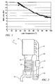
- Fig. 1 is a data graph of spin loss versus transmission fluid temperature, in accordance with the present disclosure
- Fig. 2 is a schematic illustration of an engine, transmission and exhaust system, in accordance with an alternative embodiment of the present disclosure
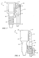
- FIG. 3 is a schematic illustration of a flow valve in accordance with the present invention.
- Fig. 4 is a schematic illustration of an engine, transmission and exhaust system, in accordance with an alternative embodiment of the present disclosure
- Fig. 5 is a schematic illustration of an engine, transmission and exhaust system, in accordance with an alternative embodiment of the present disclosure.
- Fig. 6 is a schematic illustration of an engine, transmission and exhaust system, in accordance with an alternative embodiment of the present disclosure.
- Fig. 1 is a data graph of spin loss versus transmission fluid temperature.
- Data shown in Fig. 1 demonstrate that transmission spin losses through a transmission change significantly with a change in temperature of the transmission fluid. The results indicate a relationship wherein there is a reduction in spin loss that correlates to increasing transmission fluid temperature.
- Testing was conducted on an exemplary 4-speed automatic transmission operating under specific fixed conditions, comprising third gear operation, 1500 rpm speed, with torque converter clutch locked (TCC On). The transmission demonstrated a change in spin loss from 14 Nm to less than 9 Nm when fluid temperature increased from a nominal cold-start temperature of 25 C to a typical operating temperature of 90 C.
- Embodiments of the present disclosure are operable to reduce the time transmission fluid of a transmission assembly 30 takes to reach steady state temperature.
- Figs. 2, 4, 5 and 6 each depict a powertrain system of vehicle 10, comprising an engine 20, transmission assembly 30, and an exhaust system 40 comprising an exhaust manifold 42, an exhaust pipe 46, and a catalytic converter 44.
- Figs. 2, 4, 5, and 6 each depict a heat exchanger device effective to transfer heat between engine exhaust flow and transmission fluid, each of which has been constructed in accordance with embodiments of the present disclosure.
- a transmission sump heat exchanger 32 is thermally coupled to a fluid reservoir or sump of the transmission assembly 30 and to the exhaust system 40 of engine 20 via an exhaust routing line 70.
- Transmission sump heat exchanger 32 includes an engine exhaust-to-transmission fluid heat exchanger positioned in thermal communication with the transmission fluid reservoir such that exhaust gas from engine 20 can heat the transmission fluid during a warm-up period of powertrain operation. Combustion within engine 20 quickly generates a hot exhaust gas feed stream which is expelled from engine 20 into exhaust system 40 through exhaust manifold 42. The exhaust gas feed stream flows through engine exhaust system 40 and catalytic converter 44 to flow valve 50.
- Flow valve 50 is a device selectively operative to control flow of exhaust gas through the transmission sump heat exchanger 32.
- Flow valve 50 is commonly known in the art as a diverter valve, is keyed to the temperature of the transmission fluid as measured by commonly used sensors, and may be electrically or mechanically actuated.
- Flow valve 50 may be binary in operation, effecting either a fully open or fully diverted path in exhaust pipe 46, or flow valve 50 may operate through a range of operation, from fully open to fully diverted.
- flow valve 50 may be positioned to fully close exhaust pipe 46 in favor of diverting exhaust gas into exhaust routing line 70, or flow valve 50 may be positioned at its maximum closed position to baffle a portion of the exhaust gas into exhaust gas routing line 70.
- the embodiment illustrated depicts an engine with four exhaust ports of engine 20 feeding into a single exhaust manifold 42; however, it will be appreciated by those having skill in the art that numerous configurations of engines are possible, and that the layout disclosed herein is merely exemplary.
- a single flow valve 50 may be utilized located on only one side of the exhaust system 40, or a pair of flow valves 50 may be utilized, one on each side of the exhaust system 40, with each flow valve 50 feeding to a separate exhaust routing line 70 which later join to feed into transmission sump heat exchanger 32.
- the flow valve 50 diverts some or all of the heated exhaust gas feed stream from exhaust system 40 through exhaust routing line 70 to transmission sump heat exchanger 32, wherein, as is well known in the art, structures in the heat exchanger preferably provide an expanded surface area for interface between the heated exhaust gases and the transmission fluid. Heat is drawn from the hot exhaust gas into the transmission fluid, thereby increasing the temperature of the transmission fluid. The exhaust gas returns to exhaust system 40 farther down the exhaust pipe 46 after passing through transmission sump heat exchanger 32. When the transmission fluid has reached a particular temperature set point, flow valve 50 is actuated and exhaust flow is directed away from exhaust routing line 70.
- Flow valve 50 is incorporated into exhaust pipe 46 of exhaust system 40.
- Flow valve 50 is situated such that it acts as a selective diverter of exhaust gas in exhaust system 40 into exhaust routing line 70.
- flow valve 50 may operate through a range of operation, from fully open to fully diverted.
- Position A of flow valve 50 as depicted in Fig. 3 shows flow valve 50 in a fully open mode position, directing all exhaust gas through exhaust pipe 46, thereby fully by-passing transmission sump heat exchanger 32.
- Position C of flow valve 50 as depicted in Fig.
- FIG. 3 shows flow valve 50 in a transmission heat mode position, directing all exhaust gas through exhaust pipe 46, thereby transferring as much heat to transmission sump heat exchanger 32 as possible.
- Position B of flow valve 50 as depicted in Fig. 3 shows flow valve 50 in a mid-range position, directing some of exhaust gas through exhaust pipe 46 and some of exhaust gas through transmission sump heat exchanger 32.
- exhaust gas flow, and particularly backpressure exerted within exhaust system 40 has significant impact upon the dynamics of engine 20. With such considerations in mind, it may be advantageous to only direct a portion of exhaust gas to transmission sump heat exchanger 32 depending on the flow characteristics of the exhaust routing line 70.
- engine 20 includes an intake manifold 25.
- EGR system 60 is used in certain configurations of engine 20 to reduce certain emissions and typically reroutes a portion of the exhaust gas feed flow back to the intake manifold 25.
- the embodiment which is shown in Fig. 4 depicts an exhaust gas flow routing scheme wherein exhaust gas is routed through the EGR system 60.
- EGR system 60 includes exhaust routing line 70 and EGR valve 65, which is incorporated into exhaust manifold 42 of exhaust system 40 and directs a portion of the exhaust gas feed stream, the exhaust gas recirculation feed stream ("EGR feed stream"), into exhaust routing line 70.
- Flow valve 50 is located in EGR system 60 to act as a diverter valve, selectively directing some portion of the EGR feed stream from EGR system 60 to transmission sump heat exchanger 32.
- Flow valve 50 for this embodiment acts similarly to flow valve 50 described previously in accordance with the embodiment of Fig. 2.
- flow valve 50 When the temperature of the transmission fluid is below a set point, flow valve 50 is set to a transmission heat mode position, and some or all of the exhaust gas in EGR system 60 is diverted to transmission sump heat exchanger 32 in order to increase the temperature of the transmission fluid. The exhaust gas returns to EGR system 60 farther down the exhaust routing line 70 after passing through transmission sump heat exchanger 32 and is then fed to the intake manifold 25. When the temperature of the transmission fluid achieves a set point, flow valve 50 is moved to the fully open mode position, whereby all of the EGR feedstream is directed away from transmission sump heat exchanger 32 and is routed directly to the intake manifold 25.
- Dual-mode flow valve 80 performs the functions of EGR valve 65 and flow valve 50, previously described, as a single component and is incorporated into exhaust manifold 42 of exhaust system 40. In operation, the dual-mode flow valve 80 acts to select between various functions. In a fully open mode position, dual-mode flow valve 80 directs all of the exhaust gas through exhaust system 40, thereby bypassing both EGR system 60 and transmission sump heat exchanger 32. In an EGR mode position, dual-mode flow valve 80 diverts some portion of exhaust gas from exhaust system 40 through EGR system 60 to intake manifold 25 through by-pass circuit 34.
- dual-mode flow valve 80 In a transmission heat mode position, selected as a function of transmission fluid temperature, dual-mode flow valve 80 diverts some portion of exhaust gas through transmission sump heat exchanger 32. Another mode wherein some portion of the exhaust gas from the exhaust system 40 is diverted to the intake manifold via the bypass circuit 34 and the transmission sump heat exchanger 32 is also an option. When dual-mode flow valve 80 is in any position other than fully open, the diverted gas is eventually directed to intake manifold 25.
- FIG. 6 Another alternative embodiment, which is shown in Fig. 6, includes a system wherein transmission fluid is routed out of transmission assembly 30 through transmission fluid lines 36 through an exhaust pipe heat exchanger 48 thermally coupled to a portion of exhaust pipe 46.
- Exhaust pipe heat exchanger 48 utilizes heat exchanger technology well known to those in the art and is similar to transmission sump heat exchanger 32 previously described.
- Exhaust pipe heat exchanger 48 preferably provides an expanded surface area for interface between the heated exhaust gases and the transmission fluid, allowing heat to flow from the hot exhaust gas feed stream to the transmission fluid. Flow of exhaust gas through exhaust pipe heat exchanger 48 is selectively controlled by flow valve 50, as shown.
- flow valve 50 in transmission heat mode position, selectively directs exhaust gas to exhaust pipe heat exchanger 48 when the transmission fluid temperature is below a set point or, alternatively, directs exhaust gas away from the exhaust pipe heat exchanger 48 into exhaust pipe heat exchanger by-pass circuit 49 when the transmission fluid temperature is above a set point.
- Transmission fluid acting under pressure from within transmission assembly 30, flows through a transmission line 36, through exhaust pipe heat exchanger 48, and back through another transmission line 36 to transmission assembly 30.
- Flow through transmission lines 36 may be constant, without regard to whether flow valve 50 is in open mode or diverted mode, or flow through transmission lines 36 may be selectively ceased when flow valve 50 is set to the open position. In this way, the system selectively operates to heat transmission fluid to a set point utilizing hot exhaust gas generated in engine 20.
Landscapes
- Engineering & Computer Science (AREA)
- General Engineering & Computer Science (AREA)
- Mechanical Engineering (AREA)
- Chemical & Material Sciences (AREA)
- Combustion & Propulsion (AREA)
- Exhaust Silencers (AREA)
- Exhaust-Gas Circulating Devices (AREA)
- General Details Of Gearings (AREA)
Applications Claiming Priority (2)
| Application Number | Priority Date | Filing Date | Title |
|---|---|---|---|
| US82708206P | 2006-09-27 | 2006-09-27 | |
| US11/856,229 US20080073065A1 (en) | 2006-09-27 | 2007-09-17 | Method and apparatus to transfer heat to automatic transmission fluid using engine exhaust gas feed stream |
Publications (3)
| Publication Number | Publication Date |
|---|---|
| EP1906057A2 true EP1906057A2 (de) | 2008-04-02 |
| EP1906057A3 EP1906057A3 (de) | 2011-01-05 |
| EP1906057B1 EP1906057B1 (de) | 2013-01-23 |
Family
ID=39022789
Family Applications (1)
| Application Number | Title | Priority Date | Filing Date |
|---|---|---|---|
| EP07018593A Ceased EP1906057B1 (de) | 2006-09-27 | 2007-09-21 | Verfahren und Vorrichtung zur Übertragung von Wärme zum Automatikgetriebeöl unter Verwendung des Zufuhrstroms der Motorabgase |
Country Status (2)
| Country | Link |
|---|---|
| US (2) | US20080073065A1 (de) |
| EP (1) | EP1906057B1 (de) |
Families Citing this family (9)
| Publication number | Priority date | Publication date | Assignee | Title |
|---|---|---|---|---|
| DE102008031122B4 (de) * | 2008-07-02 | 2018-11-08 | Bayerische Motoren Werke Aktiengesellschaft | Anordnung zum Aufheizen eines Kraftfahrzeuggetriebes |
| US8341950B2 (en) * | 2008-07-18 | 2013-01-01 | Ford Global Technologies, Llc | Engine exhaust system having a thermoelectric conversion device and a heat pipe |
| DE102008051268A1 (de) * | 2008-10-10 | 2010-04-15 | Mahle International Gmbh | Kühleinrichtung |
| US8353154B2 (en) * | 2009-09-21 | 2013-01-15 | GM Global Technology Operations LLC | Thermally efficient exhaust treatment system for an internal combustion engine |
| US8463495B2 (en) * | 2010-12-01 | 2013-06-11 | GM Global Technology Operations LLC | Method for controlling exhaust gas heat recovery systems in vehicles |
| US8622040B2 (en) * | 2012-03-20 | 2014-01-07 | GM Global Technology Operations LLC | Compact transmission fluid heater |
| DE102012220242A1 (de) * | 2012-11-07 | 2014-05-08 | Zf Friedrichshafen Ag | Fahrzeuggetriebe |
| US9796244B2 (en) | 2014-01-17 | 2017-10-24 | Honda Motor Co., Ltd. | Thermal management system for a vehicle and method |
| JP6354699B2 (ja) * | 2015-08-06 | 2018-07-11 | トヨタ自動車株式会社 | 熱交換装置 |
Family Cites Families (16)
| Publication number | Priority date | Publication date | Assignee | Title |
|---|---|---|---|---|
| US1358947A (en) * | 1916-08-31 | 1920-11-16 | Fulton Co | Automobile-heating system |
| US1804875A (en) * | 1926-02-02 | 1931-05-12 | Cons Car Heating Co Inc | Bus heating system |
| US1870809A (en) * | 1929-01-09 | 1932-08-09 | Standard Oil Co California | System for lubricating machinery |
| US3131757A (en) * | 1961-04-20 | 1964-05-05 | Bergstrom Mfg Co | Vehicle heating apparatus |
| US4099499A (en) * | 1976-06-21 | 1978-07-11 | Ford Motor Company | Vapor temperature controlled exhaust gas heat exchanger |
| JPS57181914A (en) * | 1981-05-02 | 1982-11-09 | Honda Motor Co Ltd | Heater for lubricating oil of internal combustion engine |
| US4391235A (en) * | 1981-05-28 | 1983-07-05 | Majkrzak David S | Vehicle exhaust gas warm-up heater system |
| JPH10318348A (ja) * | 1997-05-20 | 1998-12-04 | Hitachi Ltd | 自動車用自動変速機 |
| US6330910B1 (en) * | 1999-03-03 | 2001-12-18 | Easton Bennett | Heat exchanger for a motor vehicle exhaust |
| JP2001280200A (ja) * | 2000-03-30 | 2001-10-10 | Aisin Seiki Co Ltd | エンジンの排気ガス循環装置 |
| US6584767B1 (en) * | 2001-11-09 | 2003-07-01 | Steve Koenig | Exhaust diverter |
| BR0300426A (pt) * | 2003-02-27 | 2004-11-03 | Wahler Metalurgica Ltda | Conjunto válvula defletora de gás |
| JP4202221B2 (ja) * | 2003-09-26 | 2008-12-24 | シャープ株式会社 | 光屈折素子アレイ基板、画像表示素子および画像表示装置 |
| US7077776B2 (en) * | 2004-03-15 | 2006-07-18 | Ford Global Technologies, Llc | Transmission fluid heating using engine exhaust |
| JP2005299592A (ja) * | 2004-04-15 | 2005-10-27 | Toyota Motor Corp | 内燃機関の潤滑装置 |
| US8032979B2 (en) * | 2005-09-17 | 2011-10-11 | Hydramaster North America, Inc. | Heat exchanger |
-
2007
- 2007-09-17 US US11/856,229 patent/US20080073065A1/en not_active Abandoned
- 2007-09-21 EP EP07018593A patent/EP1906057B1/de not_active Ceased
-
2011
- 2011-05-10 US US13/104,170 patent/US8678078B2/en not_active Expired - Fee Related
Non-Patent Citations (1)
| Title |
|---|
| None |
Also Published As
| Publication number | Publication date |
|---|---|
| US20080073065A1 (en) | 2008-03-27 |
| US8678078B2 (en) | 2014-03-25 |
| EP1906057B1 (de) | 2013-01-23 |
| EP1906057A3 (de) | 2011-01-05 |
| US20110209865A1 (en) | 2011-09-01 |
Similar Documents
| Publication | Publication Date | Title |
|---|---|---|
| US8678078B2 (en) | Method and apparatus to transfer heat to automatic transmission fluid using engine exhaust gas feed stream | |
| US8413434B2 (en) | Exhaust heat recovery for transmission warm-up | |
| US8567182B2 (en) | Vehicle exhaust heat recovery system and method of managing exhaust heat | |
| US8205443B2 (en) | Heat exchanging systems for motor vehicles | |
| CN104791071B (zh) | 用于车辆的热管理系统及方法 | |
| US9097174B2 (en) | System and method for conditioning intake air to an internal combustion engine | |
| CN102356217B (zh) | 用于注油转动或摆动部件的方法和设备 | |
| CN108317024B (zh) | 用于排气热交换器的方法和系统 | |
| US7077776B2 (en) | Transmission fluid heating using engine exhaust | |
| US9567892B2 (en) | Cooling system for an internal combustion engine | |
| US8359845B2 (en) | Exhaust heat recovery and exhaust gas recirculation with common heat exchanger | |
| CN105745411B (zh) | 用于内燃机的热管理系统 | |
| EP2998536B1 (de) | Anordnung und verfahren zur regelung eines motorkühlsystems | |
| CN104420971B (zh) | 变速器机油的温度控制布置以及用于控制变速器机油的温度的方法 | |
| CN105545534B (zh) | 高效的排气热回收的排气系统和方法 | |
| US20150176445A1 (en) | Apparatus for adjusting temperature of oil for vehicle and method for controlling the apparatus | |
| CN107023364A (zh) | 用于排气热回收的方法和系统 | |
| US10253679B2 (en) | Vehicle thermal management system, and methods of use and manufacture thereof | |
| CN103635670A (zh) | 冷却系统 | |
| US5799632A (en) | Heat exchanger for a hydrocarbon fuelled motor vehicle | |
| US5377486A (en) | Catalytic converter system | |
| US20130087304A1 (en) | Exhaust gas heat recovery system | |
| US10641157B2 (en) | Thermostat and cooling system having the same | |
| JP6830376B2 (ja) | 変速機ウォーマ装置 | |
| GB2545814A (en) | Cooling apparatus for an internal combustion engine of a vehicle |
Legal Events
| Date | Code | Title | Description |
|---|---|---|---|
| PUAI | Public reference made under article 153(3) epc to a published international application that has entered the european phase |
Free format text: ORIGINAL CODE: 0009012 |
|
| AK | Designated contracting states |
Kind code of ref document: A2 Designated state(s): AT BE BG CH CY CZ DE DK EE ES FI FR GB GR HU IE IS IT LI LT LU LV MC MT NL PL PT RO SE SI SK TR |
|
| AX | Request for extension of the european patent |
Extension state: AL BA HR MK YU |
|
| PUAL | Search report despatched |
Free format text: ORIGINAL CODE: 0009013 |
|
| AK | Designated contracting states |
Kind code of ref document: A3 Designated state(s): AT BE BG CH CY CZ DE DK EE ES FI FR GB GR HU IE IS IT LI LT LU LV MC MT NL PL PT RO SE SI SK TR |
|
| AX | Request for extension of the european patent |
Extension state: AL BA HR MK RS |
|
| RAP1 | Party data changed (applicant data changed or rights of an application transferred) |
Owner name: GM GLOBAL TECHNOLOGY OPERATIONS LLC |
|
| 17P | Request for examination filed |
Effective date: 20110627 |
|
| AKX | Designation fees paid |
Designated state(s): DE |
|
| 17Q | First examination report despatched |
Effective date: 20110901 |
|
| GRAP | Despatch of communication of intention to grant a patent |
Free format text: ORIGINAL CODE: EPIDOSNIGR1 |
|
| GRAS | Grant fee paid |
Free format text: ORIGINAL CODE: EPIDOSNIGR3 |
|
| GRAA | (expected) grant |
Free format text: ORIGINAL CODE: 0009210 |
|
| AK | Designated contracting states |
Kind code of ref document: B1 Designated state(s): DE |
|
| REG | Reference to a national code |
Ref country code: DE Ref legal event code: R096 Ref document number: 602007028170 Country of ref document: DE Effective date: 20130321 |
|
| PLBE | No opposition filed within time limit |
Free format text: ORIGINAL CODE: 0009261 |
|
| STAA | Information on the status of an ep patent application or granted ep patent |
Free format text: STATUS: NO OPPOSITION FILED WITHIN TIME LIMIT |
|
| 26N | No opposition filed |
Effective date: 20131024 |
|
| REG | Reference to a national code |
Ref country code: DE Ref legal event code: R097 Ref document number: 602007028170 Country of ref document: DE Effective date: 20131024 |
|
| PGFP | Annual fee paid to national office [announced via postgrant information from national office to epo] |
Ref country code: DE Payment date: 20190910 Year of fee payment: 13 |
|
| REG | Reference to a national code |
Ref country code: DE Ref legal event code: R119 Ref document number: 602007028170 Country of ref document: DE |
|
| PG25 | Lapsed in a contracting state [announced via postgrant information from national office to epo] |
Ref country code: DE Free format text: LAPSE BECAUSE OF NON-PAYMENT OF DUE FEES Effective date: 20210401 |