EP1906080A1 - Leuchteinheit - Google Patents
Leuchteinheit Download PDFInfo
- Publication number
- EP1906080A1 EP1906080A1 EP06425669A EP06425669A EP1906080A1 EP 1906080 A1 EP1906080 A1 EP 1906080A1 EP 06425669 A EP06425669 A EP 06425669A EP 06425669 A EP06425669 A EP 06425669A EP 1906080 A1 EP1906080 A1 EP 1906080A1
- Authority
- EP
- European Patent Office
- Prior art keywords
- unity
- rod
- rods
- anyone
- bar
- Prior art date
- Legal status (The legal status is an assumption and is not a legal conclusion. Google has not performed a legal analysis and makes no representation as to the accuracy of the status listed.)
- Granted
Links
- 239000012777 electrically insulating material Substances 0.000 claims description 3
- 238000010276 construction Methods 0.000 description 4
- 239000002184 metal Substances 0.000 description 3
- 239000004020 conductor Substances 0.000 description 2
- 238000009413 insulation Methods 0.000 description 2
- 230000006978 adaptation Effects 0.000 description 1
- 238000009792 diffusion process Methods 0.000 description 1
- 230000000694 effects Effects 0.000 description 1
- 230000002093 peripheral effect Effects 0.000 description 1
- 230000001681 protective effect Effects 0.000 description 1
Images


Classifications
-
- F—MECHANICAL ENGINEERING; LIGHTING; HEATING; WEAPONS; BLASTING
- F21—LIGHTING
- F21V—FUNCTIONAL FEATURES OR DETAILS OF LIGHTING DEVICES OR SYSTEMS THEREOF; STRUCTURAL COMBINATIONS OF LIGHTING DEVICES WITH OTHER ARTICLES, NOT OTHERWISE PROVIDED FOR
- F21V21/00—Supporting, suspending, or attaching arrangements for lighting devices; Hand grips
- F21V21/14—Adjustable mountings
- F21V21/30—Pivoted housings or frames
-
- F—MECHANICAL ENGINEERING; LIGHTING; HEATING; WEAPONS; BLASTING
- F21—LIGHTING
- F21S—NON-PORTABLE LIGHTING DEVICES; SYSTEMS THEREOF; VEHICLE LIGHTING DEVICES SPECIALLY ADAPTED FOR VEHICLE EXTERIORS
- F21S8/00—Lighting devices intended for fixed installation
- F21S8/04—Lighting devices intended for fixed installation intended only for mounting on a ceiling or the like overhead structures
- F21S8/06—Lighting devices intended for fixed installation intended only for mounting on a ceiling or the like overhead structures by suspension
-
- F—MECHANICAL ENGINEERING; LIGHTING; HEATING; WEAPONS; BLASTING
- F21—LIGHTING
- F21V—FUNCTIONAL FEATURES OR DETAILS OF LIGHTING DEVICES OR SYSTEMS THEREOF; STRUCTURAL COMBINATIONS OF LIGHTING DEVICES WITH OTHER ARTICLES, NOT OTHERWISE PROVIDED FOR
- F21V21/00—Supporting, suspending, or attaching arrangements for lighting devices; Hand grips
- F21V21/34—Supporting elements displaceable along a guiding element
- F21V21/35—Supporting elements displaceable along a guiding element with direct electrical contact between the supporting element and electric conductors running along the guiding element
Definitions
- the present invention relates to a lighting unity mainly to be used in rooms of dwelling houses.
- these unities comprise one or more lamp-holders, each of which is adapted to support a respective illuminating body such as an incandescent light bulb for example.
- Lamp-holders are provided with a pair of electric connectors, operatively connected to the domestic mains system to energise the respective lamps and supported by respective supporting frames that can have different shapes and sizes depending on the particular construction and aesthetic requirements.
- frames comprising electrically conductive metal bars with which a series of lamp-holders is associated, said lamp-holders being suitably spaced apart to diffuse light in a homogeneous manner.
- these types of frames consist of a pair of bars each of which corresponds to a respective electric pole and with which said connectors for each lamp are in engagement.
- low-voltage powered lighting unities are also manufactured, by way of example in the order of 12-24 volts, in which possible protective insulation members placed around the frame bars can be eliminated. For this reason the energised parts that in this case consist of said bars, appear to be externally in sight, giving the whole lighting unity an excellent aesthetic effect.
- the present invention aims at providing a lighting unity capable of meeting the above mentioned requirements in a satisfactory manner.
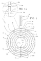
- a lighting unity in accordance with the present invention has been generally identified with reference numeral 1.
- the low-voltage powered lighting unity just as an indication in the order of 12-24 volts, is particularly adapted to be used in domestic rooms, shops, offices or other premises in dwelling houses.
- unity 1 comprises a plurality of supporting elements 2, parallel to each other, each of which has at least one pair of bars 3a, 3b made of an electrically conductive material.
- Each bar 3a, 3b and consequently each supporting element 2 preferably has an annular conformation with a circular extension, as clearly shown in Figs. 1 and 4.
- two engagement portions 2a are defined that are opposite to each other and each of which is connected to a respective rod 4a, 4b, as better described in the following.
- each supporting element 2 can have a substantially C-shaped conformation, with an arched extension or according to a broken line following an angled path, with the engagement portions 2a located close to respective opposite ends of the supporting element 2.
- Fig. 1 three mutually parallel and concentric supporting elements 2 are shown in Fig. 1, each of which is made up of a first and a second bars 3a, 3b that are mutually spaced apart, have a circular conformation and are concentric with each other.
- the first bar 3a of each supporting element 2 is arranged in a circumference internal to the second bar 3b of the adjacent element 2.
- each supporting element 2 can have any conformation and any number of bars 3a, 3b depending on the different aesthetic and lighting requirements.
- each supporting element 2 supports a series of lamp-holders 5 distributed along the whole peripheral extension of the support 2 itself and each interposed between the bars 3a, 3b of the respective supporting element 2.
- Each lamp-holder 5 has a fitting portion 6 for a respective illuminating body 7, such as a low-voltage powered incandescent light bulb. Extending from opposite sides of the fitting portion 6 are two connecting portions 8 that are each electrically connected to one of the bars 3a, 3b to power said illuminating body 7.
- the connecting portions 8 are secured to the respective bars 3a, 3b by means of suitable fastening members such as screws 9 passing through respective holes formed in the bars 3a, 3b themselves. Under this situation the lamp-holders 5 also perform functions of mechanical connection between the bars 3a, 3b of each supporting element 2, making said bars integral with each other.
- the unity 1 further comprises a first and a second rods 4a, 4b for electric supply, which rods are substantially coaxial with each other and each electrically connectable to a respective electric pole of a feeding line.
- rods 4a, 4b are in mutual alignment and located at mutually opposite positions relative to the supporting elements 2, close to the engagement portions 2a thereof.
- the rods 4a, 4b preferably have a substantially cylindrical conformation with a circular cross section and are such disposed that their respective longitudinal axes are coaxial along a diametrical line with respect to said supporting elements 2.
- the rods 4a, 4b consequently have respective inner ends 10 mutually spaced apart and facing each other, being disposed internally of the first bar 3a of the supporting element 2 having the smallest diameter, and respective outer ends 11 opposite to the inner ends 10 and projecting from the second bar 3b of the supporting element 2 having the largest diameter.
- Each conductive bar 3a, 3b is rotatably associated with the first and second rods 4a, 4b to pivot around the longitudinal axes of the rods 4a, 4b.
- each rod 4a, 4b extends through a series of through cavities 12 coaxial with each other and each made in one of the bars 3a, 3b. Therefore each bar 3a, 3b is provided with two mutually coaxial cavities 12 through which the respective rods 4a, 4b extend.
- the supporting elements 2 can rotate in an independent manner from each other to be oriented at choice, depending on the configuration that one wishes to give to unity 1.
- each conductive bar 3a, 3b is electrically insulated from one of the rods 4a, 4b and electrically connected to the other rod 4a, 4b.
- first conductive bar 3a of each supporting element 2 is electrically connected to the first rod 4a and electrically insulated from the second rod 4b.
- the second bar 3b of each supporting element 2 is electrically connected to the second rod 4b- and electrically insulated from the first rod 4a.
- each first bar 3a has a first sleeve 13a fitted in the respective cavity 12 in which the second rod 4b is caused to pass
- each second bar 3b has a second sleeve 13b fitted in the respective cavity 12 in which the first rod 4a is caused to pass.
- each bar 3a, 3b is electrically connected to a respective rod 4a, 4b and insulated from the other rod 4a, 4b by interposition of said sleeve 13a, 13b.
- the unity 1 further has a box-shaped body 14 disposed on the outer end 11 of the first rod 4a. As illustrated in Fig. 3, where only one top portion of the unity 1 sectioned along a diametrical plane relative to the outermost supporting element 2 is shown, a first and a second electric connectors 15a, 15b are housed within the box-shaped body 14.
- the first connector 15a is in engagement with the outer end 11 of the first rod 4a, while the second connector 15b is associated with the second bar 3b that, as above described, is electrically insulated from the first rod 4a.
- Each electric connector 15a, 15b has a substantially cylindrical conformation and is adapted to be connected to a respective hanging and electrical-energy-supplying or powering element 16, so that unity 1 can be hung from a ceiling with the respective rods 4a, 4b disposed vertically.
- the hanging and powering elements 16 represented as distinct components in Figs. 1 and 2, can possibly be integrated into a single structure in the form of a cable or bar incorporating two or more conductors.
- Fig. 4 Shown in Fig. 4 is the unity 1 in accordance with a second embodiment, in which each rod 4a, 4b has a respective electric connector 17 projecting from the first end 10 and ready for connection with a hanging and powering cable.
- the electric connectors 17 have a substantially cylindrical conformation and extend at right angles to the longitudinal extension of the rods 4a, 4b. Under this situation, unity 1 can be hung from the ceiling with the respective rods 4a, 4b disposed horizontally.
- stiff metal bars can be used as the hanging and powering elements, which metal bars are able to support the lighting unity from below as well, in the case of a floor lamp or a lamp in overhang from a vertical wall.
- the user can intervene manually on the individual supporting elements 2 to vary the configuration of the unity 1 itself.
- orientation of the bars 3a, 3b can be carried out so as to adapt the structure of the lighting unity 1 to the surrounding environment.
- the lamp-holders 5 can be oriented depending on the different lighting requirements.
- a further advantage of the present invention resides in the simplicity of the unity 1 in terms of structure and operation, as replacements are not required for making it suitable for use in the place where it is installed.
Landscapes
- Engineering & Computer Science (AREA)
- General Engineering & Computer Science (AREA)
- Non-Portable Lighting Devices Or Systems Thereof (AREA)
- Fastening Of Light Sources Or Lamp Holders (AREA)
- Electrophonic Musical Instruments (AREA)
- Instruments For Measurement Of Length By Optical Means (AREA)
- Devices For Indicating Variable Information By Combining Individual Elements (AREA)
Priority Applications (3)
| Application Number | Priority Date | Filing Date | Title |
|---|---|---|---|
| EP06425669A EP1906080B1 (de) | 2006-09-28 | 2006-09-28 | Leuchteinheit |
| DE602006003768T DE602006003768D1 (de) | 2006-09-28 | 2006-09-28 | Leuchteinheit |
| AT06425669T ATE414870T1 (de) | 2006-09-28 | 2006-09-28 | Leuchteinheit |
Applications Claiming Priority (1)
| Application Number | Priority Date | Filing Date | Title |
|---|---|---|---|
| EP06425669A EP1906080B1 (de) | 2006-09-28 | 2006-09-28 | Leuchteinheit |
Publications (2)
| Publication Number | Publication Date |
|---|---|
| EP1906080A1 true EP1906080A1 (de) | 2008-04-02 |
| EP1906080B1 EP1906080B1 (de) | 2008-11-19 |
Family
ID=37672288
Family Applications (1)
| Application Number | Title | Priority Date | Filing Date |
|---|---|---|---|
| EP06425669A Not-in-force EP1906080B1 (de) | 2006-09-28 | 2006-09-28 | Leuchteinheit |
Country Status (3)
| Country | Link |
|---|---|
| EP (1) | EP1906080B1 (de) |
| AT (1) | ATE414870T1 (de) |
| DE (1) | DE602006003768D1 (de) |
Cited By (4)
| Publication number | Priority date | Publication date | Assignee | Title |
|---|---|---|---|---|
| ITMI20100610A1 (it) * | 2010-04-09 | 2011-10-10 | Bevilacqua Carlotta Francesca Isolina Maria De | Apparecchio di illuminazione a geometria variabile |
| US8770792B2 (en) | 2010-04-09 | 2014-07-08 | Carlotta Francesca Isolina Maria de BEVILACQUA | Variable configuration lighting apparatus |
| EP2511600A3 (de) * | 2011-04-11 | 2015-01-07 | Swarovski Lighting, Ltd. | Beleuchtungskörper, Verfahren zum Aufhängen einer Vielzahl von Lichtquellen, Verzierungsmontage und Verfahren zur Montage einer Verzierung |
| WO2018174964A1 (en) * | 2017-03-24 | 2018-09-27 | Swarovski Lighting, Ltd. | Adjustably configurable suspended fixtures, lighting fixtures, and method for suspending fixtures and lighting fixtures |
Citations (3)
| Publication number | Priority date | Publication date | Assignee | Title |
|---|---|---|---|---|
| US5440469A (en) * | 1994-04-08 | 1995-08-08 | Gomes; Roy | Low voltage track lighting fixture |
| US6135617A (en) * | 1999-10-21 | 2000-10-24 | Lai; Wei-Cheng | Folding illumination skeleton |
| DE19917401A1 (de) * | 1999-04-16 | 2000-10-26 | Hauke Haller | Beleuchtungskörper |
-
2006
- 2006-09-28 AT AT06425669T patent/ATE414870T1/de not_active IP Right Cessation
- 2006-09-28 DE DE602006003768T patent/DE602006003768D1/de not_active Expired - Fee Related
- 2006-09-28 EP EP06425669A patent/EP1906080B1/de not_active Not-in-force
Patent Citations (3)
| Publication number | Priority date | Publication date | Assignee | Title |
|---|---|---|---|---|
| US5440469A (en) * | 1994-04-08 | 1995-08-08 | Gomes; Roy | Low voltage track lighting fixture |
| DE19917401A1 (de) * | 1999-04-16 | 2000-10-26 | Hauke Haller | Beleuchtungskörper |
| US6135617A (en) * | 1999-10-21 | 2000-10-24 | Lai; Wei-Cheng | Folding illumination skeleton |
Cited By (6)
| Publication number | Priority date | Publication date | Assignee | Title |
|---|---|---|---|---|
| ITMI20100610A1 (it) * | 2010-04-09 | 2011-10-10 | Bevilacqua Carlotta Francesca Isolina Maria De | Apparecchio di illuminazione a geometria variabile |
| EP2375146A1 (de) * | 2010-04-09 | 2011-10-12 | Carlotta Francesca Isolina Maria de Bevilacqua | Beleuchtungsvorrichtung mit variabler Geometrie |
| US8770792B2 (en) | 2010-04-09 | 2014-07-08 | Carlotta Francesca Isolina Maria de BEVILACQUA | Variable configuration lighting apparatus |
| EP2511600A3 (de) * | 2011-04-11 | 2015-01-07 | Swarovski Lighting, Ltd. | Beleuchtungskörper, Verfahren zum Aufhängen einer Vielzahl von Lichtquellen, Verzierungsmontage und Verfahren zur Montage einer Verzierung |
| WO2018174964A1 (en) * | 2017-03-24 | 2018-09-27 | Swarovski Lighting, Ltd. | Adjustably configurable suspended fixtures, lighting fixtures, and method for suspending fixtures and lighting fixtures |
| US10704775B2 (en) | 2017-03-24 | 2020-07-07 | Swarovski Lighting, Ltd. | Adjustably configurable suspended fixtures, lighting fixtures, and method for suspending fixtures and lighting fixtures |
Also Published As
| Publication number | Publication date |
|---|---|
| ATE414870T1 (de) | 2008-12-15 |
| DE602006003768D1 (de) | 2009-01-02 |
| EP1906080B1 (de) | 2008-11-19 |
Similar Documents
| Publication | Publication Date | Title |
|---|---|---|
| US7025480B2 (en) | Lighting fixture with enclosed wiring | |
| US20170191643A1 (en) | Interchangeable lighting fixtures for track and wall lighting system | |
| US20080123354A1 (en) | Telescoping power medium | |
| US5440469A (en) | Low voltage track lighting fixture | |
| US10458635B2 (en) | Lighting system | |
| US6866396B2 (en) | Illuminating device with rotatably adjustable support | |
| EP1906080B1 (de) | Leuchteinheit | |
| US6494601B2 (en) | Modular cluster lighting fixture | |
| US5709461A (en) | Electrical concertina-type lamp | |
| US2769083A (en) | Lighting fixture for circular fluorescent lamps | |
| KR101634623B1 (ko) | 막대형 조명기구 | |
| JP7354759B2 (ja) | 落下防止ワイヤ、及びランプユニット | |
| EP2620053B1 (de) | Forstwirtschaftliche Beleuchtung | |
| KR200407087Y1 (ko) | 국부조명용 조명기구 | |
| CN219933865U (zh) | 一种可快速延长灯杆的吊灯 | |
| GB2417370A (en) | Light fitting for use with existing pendant bulb holder | |
| US20120212932A1 (en) | Spotlight | |
| EP2697563A1 (de) | Einrohrsystem für decken-und wandbeleuchtung mit led-lichtquellen | |
| JPH10299211A (ja) | 照明付手摺りブラケット | |
| CN216243912U (zh) | 一种组合式吊灯 | |
| JPS5923315Y2 (ja) | 照明器具 | |
| CN208670789U (zh) | 一种带有led电源的吸顶灯固定装置 | |
| KR20090005855U (ko) | 회전조명부를 갖는 천정조명등 | |
| JPH04308602A (ja) | 連用蛍光灯システム | |
| KR200362107Y1 (ko) | 조명등 장착장치 |
Legal Events
| Date | Code | Title | Description |
|---|---|---|---|
| PUAI | Public reference made under article 153(3) epc to a published international application that has entered the european phase |
Free format text: ORIGINAL CODE: 0009012 |
|
| 17P | Request for examination filed |
Effective date: 20070605 |
|
| AK | Designated contracting states |
Kind code of ref document: A1 Designated state(s): AT BE BG CH CY CZ DE DK EE ES FI FR GB GR HU IE IS IT LI LT LU LV MC NL PL PT RO SE SI SK TR |
|
| AX | Request for extension of the european patent |
Extension state: AL BA HR MK YU |
|
| GRAP | Despatch of communication of intention to grant a patent |
Free format text: ORIGINAL CODE: EPIDOSNIGR1 |
|
| GRAS | Grant fee paid |
Free format text: ORIGINAL CODE: EPIDOSNIGR3 |
|
| GRAA | (expected) grant |
Free format text: ORIGINAL CODE: 0009210 |
|
| AK | Designated contracting states |
Kind code of ref document: B1 Designated state(s): AT BE BG CH CY CZ DE DK EE ES FI FR GB GR HU IE IS IT LI LT LU LV MC NL PL PT RO SE SI SK TR |
|
| REG | Reference to a national code |
Ref country code: GB Ref legal event code: FG4D |
|
| REG | Reference to a national code |
Ref country code: CH Ref legal event code: EP |
|
| AKX | Designation fees paid |
Designated state(s): AT BE BG CH CY CZ DE DK EE ES FI FR GB GR HU IE IS IT LI LT LU LV MC NL PL PT RO SE SI SK TR |
|
| REG | Reference to a national code |
Ref country code: IE Ref legal event code: FG4D |
|
| REF | Corresponds to: |
Ref document number: 602006003768 Country of ref document: DE Date of ref document: 20090102 Kind code of ref document: P |
|
| LTIE | Lt: invalidation of european patent or patent extension |
Effective date: 20081119 |
|
| PG25 | Lapsed in a contracting state [announced via postgrant information from national office to epo] |
Ref country code: ES Free format text: LAPSE BECAUSE OF FAILURE TO SUBMIT A TRANSLATION OF THE DESCRIPTION OR TO PAY THE FEE WITHIN THE PRESCRIBED TIME-LIMIT Effective date: 20090301 Ref country code: LT Free format text: LAPSE BECAUSE OF FAILURE TO SUBMIT A TRANSLATION OF THE DESCRIPTION OR TO PAY THE FEE WITHIN THE PRESCRIBED TIME-LIMIT Effective date: 20081119 Ref country code: AT Free format text: LAPSE BECAUSE OF FAILURE TO SUBMIT A TRANSLATION OF THE DESCRIPTION OR TO PAY THE FEE WITHIN THE PRESCRIBED TIME-LIMIT Effective date: 20081119 |
|
| NLV1 | Nl: lapsed or annulled due to failure to fulfill the requirements of art. 29p and 29m of the patents act | ||
| PG25 | Lapsed in a contracting state [announced via postgrant information from national office to epo] |
Ref country code: SI Free format text: LAPSE BECAUSE OF FAILURE TO SUBMIT A TRANSLATION OF THE DESCRIPTION OR TO PAY THE FEE WITHIN THE PRESCRIBED TIME-LIMIT Effective date: 20081119 Ref country code: PL Free format text: LAPSE BECAUSE OF FAILURE TO SUBMIT A TRANSLATION OF THE DESCRIPTION OR TO PAY THE FEE WITHIN THE PRESCRIBED TIME-LIMIT Effective date: 20081119 Ref country code: FI Free format text: LAPSE BECAUSE OF FAILURE TO SUBMIT A TRANSLATION OF THE DESCRIPTION OR TO PAY THE FEE WITHIN THE PRESCRIBED TIME-LIMIT Effective date: 20081119 Ref country code: IS Free format text: LAPSE BECAUSE OF FAILURE TO SUBMIT A TRANSLATION OF THE DESCRIPTION OR TO PAY THE FEE WITHIN THE PRESCRIBED TIME-LIMIT Effective date: 20090319 Ref country code: NL Free format text: LAPSE BECAUSE OF FAILURE TO SUBMIT A TRANSLATION OF THE DESCRIPTION OR TO PAY THE FEE WITHIN THE PRESCRIBED TIME-LIMIT Effective date: 20081119 Ref country code: LV Free format text: LAPSE BECAUSE OF FAILURE TO SUBMIT A TRANSLATION OF THE DESCRIPTION OR TO PAY THE FEE WITHIN THE PRESCRIBED TIME-LIMIT Effective date: 20081119 |
|
| PG25 | Lapsed in a contracting state [announced via postgrant information from national office to epo] |
Ref country code: BE Free format text: LAPSE BECAUSE OF FAILURE TO SUBMIT A TRANSLATION OF THE DESCRIPTION OR TO PAY THE FEE WITHIN THE PRESCRIBED TIME-LIMIT Effective date: 20081119 Ref country code: EE Free format text: LAPSE BECAUSE OF FAILURE TO SUBMIT A TRANSLATION OF THE DESCRIPTION OR TO PAY THE FEE WITHIN THE PRESCRIBED TIME-LIMIT Effective date: 20081119 Ref country code: BG Free format text: LAPSE BECAUSE OF FAILURE TO SUBMIT A TRANSLATION OF THE DESCRIPTION OR TO PAY THE FEE WITHIN THE PRESCRIBED TIME-LIMIT Effective date: 20090219 Ref country code: DK Free format text: LAPSE BECAUSE OF FAILURE TO SUBMIT A TRANSLATION OF THE DESCRIPTION OR TO PAY THE FEE WITHIN THE PRESCRIBED TIME-LIMIT Effective date: 20081119 Ref country code: RO Free format text: LAPSE BECAUSE OF FAILURE TO SUBMIT A TRANSLATION OF THE DESCRIPTION OR TO PAY THE FEE WITHIN THE PRESCRIBED TIME-LIMIT Effective date: 20081119 |
|
| PG25 | Lapsed in a contracting state [announced via postgrant information from national office to epo] |
Ref country code: SE Free format text: LAPSE BECAUSE OF FAILURE TO SUBMIT A TRANSLATION OF THE DESCRIPTION OR TO PAY THE FEE WITHIN THE PRESCRIBED TIME-LIMIT Effective date: 20090219 Ref country code: PT Free format text: LAPSE BECAUSE OF FAILURE TO SUBMIT A TRANSLATION OF THE DESCRIPTION OR TO PAY THE FEE WITHIN THE PRESCRIBED TIME-LIMIT Effective date: 20090420 Ref country code: CZ Free format text: LAPSE BECAUSE OF FAILURE TO SUBMIT A TRANSLATION OF THE DESCRIPTION OR TO PAY THE FEE WITHIN THE PRESCRIBED TIME-LIMIT Effective date: 20081119 |
|
| PLBE | No opposition filed within time limit |
Free format text: ORIGINAL CODE: 0009261 |
|
| STAA | Information on the status of an ep patent application or granted ep patent |
Free format text: STATUS: NO OPPOSITION FILED WITHIN TIME LIMIT |
|
| PG25 | Lapsed in a contracting state [announced via postgrant information from national office to epo] |
Ref country code: SK Free format text: LAPSE BECAUSE OF FAILURE TO SUBMIT A TRANSLATION OF THE DESCRIPTION OR TO PAY THE FEE WITHIN THE PRESCRIBED TIME-LIMIT Effective date: 20081119 |
|
| 26N | No opposition filed |
Effective date: 20090820 |
|
| PG25 | Lapsed in a contracting state [announced via postgrant information from national office to epo] |
Ref country code: MC Free format text: LAPSE BECAUSE OF NON-PAYMENT OF DUE FEES Effective date: 20090930 |
|
| PGFP | Annual fee paid to national office [announced via postgrant information from national office to epo] |
Ref country code: IT Payment date: 20090930 Year of fee payment: 4 |
|
| REG | Reference to a national code |
Ref country code: IE Ref legal event code: MM4A |
|
| REG | Reference to a national code |
Ref country code: FR Ref legal event code: ST Effective date: 20100531 |
|
| PG25 | Lapsed in a contracting state [announced via postgrant information from national office to epo] |
Ref country code: FR Free format text: LAPSE BECAUSE OF NON-PAYMENT OF DUE FEES Effective date: 20090930 Ref country code: IE Free format text: LAPSE BECAUSE OF NON-PAYMENT OF DUE FEES Effective date: 20090928 Ref country code: DE Free format text: LAPSE BECAUSE OF NON-PAYMENT OF DUE FEES Effective date: 20100401 |
|
| PG25 | Lapsed in a contracting state [announced via postgrant information from national office to epo] |
Ref country code: GR Free format text: LAPSE BECAUSE OF FAILURE TO SUBMIT A TRANSLATION OF THE DESCRIPTION OR TO PAY THE FEE WITHIN THE PRESCRIBED TIME-LIMIT Effective date: 20090220 |
|
| PG25 | Lapsed in a contracting state [announced via postgrant information from national office to epo] |
Ref country code: LU Free format text: LAPSE BECAUSE OF NON-PAYMENT OF DUE FEES Effective date: 20090928 |
|
| REG | Reference to a national code |
Ref country code: CH Ref legal event code: PL |
|
| GBPC | Gb: european patent ceased through non-payment of renewal fee |
Effective date: 20100928 |
|
| PG25 | Lapsed in a contracting state [announced via postgrant information from national office to epo] |
Ref country code: IT Free format text: LAPSE BECAUSE OF NON-PAYMENT OF DUE FEES Effective date: 20100928 |
|
| PG25 | Lapsed in a contracting state [announced via postgrant information from national office to epo] |
Ref country code: HU Free format text: LAPSE BECAUSE OF FAILURE TO SUBMIT A TRANSLATION OF THE DESCRIPTION OR TO PAY THE FEE WITHIN THE PRESCRIBED TIME-LIMIT Effective date: 20090520 |
|
| PG25 | Lapsed in a contracting state [announced via postgrant information from national office to epo] |
Ref country code: CH Free format text: LAPSE BECAUSE OF NON-PAYMENT OF DUE FEES Effective date: 20100930 Ref country code: LI Free format text: LAPSE BECAUSE OF NON-PAYMENT OF DUE FEES Effective date: 20100930 |
|
| PG25 | Lapsed in a contracting state [announced via postgrant information from national office to epo] |
Ref country code: GB Free format text: LAPSE BECAUSE OF NON-PAYMENT OF DUE FEES Effective date: 20100928 Ref country code: TR Free format text: LAPSE BECAUSE OF FAILURE TO SUBMIT A TRANSLATION OF THE DESCRIPTION OR TO PAY THE FEE WITHIN THE PRESCRIBED TIME-LIMIT Effective date: 20081119 |
|
| PG25 | Lapsed in a contracting state [announced via postgrant information from national office to epo] |
Ref country code: CY Free format text: LAPSE BECAUSE OF FAILURE TO SUBMIT A TRANSLATION OF THE DESCRIPTION OR TO PAY THE FEE WITHIN THE PRESCRIBED TIME-LIMIT Effective date: 20081119 |