EP1906201A1 - Trägerphasen-Mehrdeutigkeitsauflösung mit mehreren Referenzempfängern - Google Patents
Trägerphasen-Mehrdeutigkeitsauflösung mit mehreren Referenzempfängern Download PDFInfo
- Publication number
- EP1906201A1 EP1906201A1 EP07117206A EP07117206A EP1906201A1 EP 1906201 A1 EP1906201 A1 EP 1906201A1 EP 07117206 A EP07117206 A EP 07117206A EP 07117206 A EP07117206 A EP 07117206A EP 1906201 A1 EP1906201 A1 EP 1906201A1
- Authority
- EP
- European Patent Office
- Prior art keywords
- antenna
- phase
- master
- antennae
- carrier
- Prior art date
- Legal status (The legal status is an assumption and is not a legal conclusion. Google has not performed a legal analysis and makes no representation as to the accuracy of the status listed.)
- Withdrawn
Links
- 238000005259 measurement Methods 0.000 claims abstract description 55
- 238000000034 method Methods 0.000 claims abstract description 33
- 238000012545 processing Methods 0.000 claims description 5
- 238000012795 verification Methods 0.000 claims description 2
- 238000004891 communication Methods 0.000 description 7
- 238000010586 diagram Methods 0.000 description 6
- 238000013459 approach Methods 0.000 description 5
- RYGMFSIKBFXOCR-UHFFFAOYSA-N Copper Chemical compound [Cu] RYGMFSIKBFXOCR-UHFFFAOYSA-N 0.000 description 1
- 230000006978 adaptation Effects 0.000 description 1
- 239000006227 byproduct Substances 0.000 description 1
- 239000000969 carrier Substances 0.000 description 1
- 230000006870 function Effects 0.000 description 1
- 239000013307 optical fiber Substances 0.000 description 1
- 230000004044 response Effects 0.000 description 1
Images


Classifications
-
- G—PHYSICS
- G01—MEASURING; TESTING
- G01S—RADIO DIRECTION-FINDING; RADIO NAVIGATION; DETERMINING DISTANCE OR VELOCITY BY USE OF RADIO WAVES; LOCATING OR PRESENCE-DETECTING BY USE OF THE REFLECTION OR RERADIATION OF RADIO WAVES; ANALOGOUS ARRANGEMENTS USING OTHER WAVES
- G01S5/00—Position-fixing by co-ordinating two or more direction or position line determinations; Position-fixing by co-ordinating two or more distance determinations
- G01S5/02—Position-fixing by co-ordinating two or more direction or position line determinations; Position-fixing by co-ordinating two or more distance determinations using radio waves
- G01S5/0284—Relative positioning
-
- G—PHYSICS
- G01—MEASURING; TESTING
- G01S—RADIO DIRECTION-FINDING; RADIO NAVIGATION; DETERMINING DISTANCE OR VELOCITY BY USE OF RADIO WAVES; LOCATING OR PRESENCE-DETECTING BY USE OF THE REFLECTION OR RERADIATION OF RADIO WAVES; ANALOGOUS ARRANGEMENTS USING OTHER WAVES
- G01S19/00—Satellite radio beacon positioning systems; Determining position, velocity or attitude using signals transmitted by such systems
- G01S19/38—Determining a navigation solution using signals transmitted by a satellite radio beacon positioning system
- G01S19/39—Determining a navigation solution using signals transmitted by a satellite radio beacon positioning system the satellite radio beacon positioning system transmitting time-stamped messages, e.g. GPS [Global Positioning System], GLONASS [Global Orbiting Navigation Satellite System] or GALILEO
- G01S19/42—Determining position
- G01S19/43—Determining position using carrier phase measurements, e.g. kinematic positioning; using long or short baseline interferometry
- G01S19/44—Carrier phase ambiguity resolution; Floating ambiguity; LAMBDA [Least-squares AMBiguity Decorrelation Adjustment] method
Definitions
- GPS global positioning system
- Availability and continuity provide assurances that the system will be available not only at the beginning of the operation, but throughout the entire duration of the flight.
- GNSS Global Navigation Satellite System
- Carrier phase measurements are ambiguous by an unknown, integer number of cycles. These integer ambiguity parameters need to be resolved before carrier-phase observations can begin to serve as very precise range measurements.
- reliable real-time ambiguity resolution is necessary.
- short-distance baseline with current GPS, the reliability of ambiguity resolution with single-epoch data is not high. This makes it impossible to realize real-time precise navigation for safety-related applications.
- medium- and long-distance baselines with current GPS, it generally takes more than twenty minutes to get reliable ambiguity resolution. This low efficiency makes it impossible for global positioning system to be used in many applications where both high precision and high efficiency are needed.
- a first aspect of the present invention includes a method to determine a relative position between antennae comprising generating phase carrier measurements for a carrier frequency and at least three antennae including a master antenna and other antennae, generating phase integer sets based on the phase carrier measurements, and calculating a relative position between the master antenna and at least one other antenna based on the generated phase integer sets and a fixed baseline between two of the other antennae.
- Figure 1 is a block diagram of one embodiment of a system in accordance with the present invention.
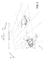
- Figure 2 shows one embodiment of an implementation of a system in accordance with the present invention.
- Figure 3 is a flow diagram of one embodiment of a method to determine a relative position between antennae in accordance with the present invention.
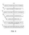
- Figure 4 is a flow diagram of one embodiment of a method to determine a relative position between a master antenna and either a first antenna or a second antenna in accordance with the present invention.
- FIG. 1 is a block diagram of one embodiment of a system 10 in accordance with the present invention.
- System 10 comprises at least three antennae, such as a master antenna 20, and at least two other antennae represented generally by the numeral 45.
- the other antennae 45 include a first antenna 30 and a second antenna 40.
- the system 10 also includes a master receiver 22, and other receivers represented generally by the numeral 35.
- the other receivers 35 comprise a first receiver 32 and a second receiver 43.
- the system 10 also includes a programmable processor 50, a memory 28, and instructions 120, e. g., software, firmware or other program code.
- the instructions 120 are stored in a storage medium 122.
- the master receiver 22, the other receivers 35, and the memory 28 are communicatively coupled to the programmable processor 50.
- the other receivers 35 are communicatively coupled to the programmable processor 50 via a wireless communication link (for example, a radio-frequency (RF) communication link).
- the other receivers 35 are communicatively coupled to the programmable processor 50 via a wired (for example, an optical fiber or copper wire communication link) and wireless communication link.
- the master receiver 22 is communicatively coupled to the programmable processor 50 via a wireless communication link. In yet another implementation of this embodiment, the master receiver 22 is communicatively coupled via a wired communication link. In yet another implementation of this embodiment, the master receiver 22 is communicatively coupled via a wired and a wireless communication link. In yet another implementation of this embodiment, at least one Kalman filter is included in the instructions 120 executed by the programmable processor 50.
- a plurality of navigational satellites 100, 102, and 104 emit global positioning system signals, the wavefronts of which are shown and represented generally by the numeral 200 (also referred to herein as "signals 200").
- the signals 200 are transmitted at a carrier frequency ⁇ c that is equal to the speed of light divided by the carrier wavelength ⁇ c .
- the master antenna 20, the first antenna 30, and the second antenna 40 each receive the global positioning system signals 200 from the plurality of navigational satellites 100, 102, and 104 within range of the antennae 20, 30, and 40.
- the master antenna 20 is also referred to herein as “user antenna 20" and the other antennae 45 are also referred to herein as “slave antennae 45,” or “reference antennae 45.”
- the plurality of navigational satellites 100, 102, and 104 are included in the system 10.
- the master receiver 22 is communicatively coupled to the master antenna 20.
- the master receiver 22 tracks and demodulates the signals 200 received at the master antenna 20 from the plurality of navigational satellites 100, 102, and 104.
- the master receiver 22 creates pseudo-range data and carrier phase measurement responsive to receiving the global positioning system signals 200.
- the pseudo-range data and carrier phase measurements generated at the master receiver 22 are sent to the programmable processor 50.
- the master antenna 20, the master receiver 22 and the programmable processor 50 are co-located.
- the master antenna 20, the master receiver 22 and the programmable processor 50 are co-located in an aircraft.
- At least two other receivers 35 are communicatively coupled to a respective one of the other antennae 45.
- Each of the other receivers 35 tracks and demodulates the signals 200 received from the plurality of navigational satellites 100, 102 and 104 at an associated other antennae 45.
- Each of the other receivers 35 creates pseudo-range data and carrier phase measurements for the associated other antennae 45.
- the pseudo-range data and carrier phase measurements generated at the other receivers 35 are sent to the programmable processor 50.
- the first receiver 32 is communicatively coupled to antenna 30.
- the first receiver 32 tracks and demodulates the signals 200 received at the first antenna 30 from the plurality of navigational satellites 100, 102 and 104.
- the first receiver 32 creates pseudo-range data and carrier phase measurements for the first antenna 30 and sends the generated pseudo-range data and carrier phase measurements to the programmable processor 50.
- the second receiver 42 is communicatively coupled to antenna 40.
- the second receiver 42 tracks and demodulates the signals 200 received at the second antenna 40 from the plurality of navigational satellites 100, 102 and 104.
- the second receiver 42 creates pseudo-range data and carrier phase measurements for the second antenna 40 and sends the generated pseudo-range data and carrier phase measurements to the programmable processor 50.
- Each of the other antennae 45 forms a baseline with the master antenna 20.
- the first antenna 30 forms a first baseline D 1 with the master antenna 20.
- the first baseline D 1 is directionally represented as a first baseline vector 151 from the master antenna 20 to the first antenna 30.
- the second antenna 40 forms a second baseline D 2 with the master antenna 20.
- the second baseline D 2 is directionally represented as second baseline vector 152 from the second antenna 40 to the master antenna 20.
- At least two of the other antennae 45 also form a fixed baseline D fix with each other.
- the fixed baseline D fix is directionally represented as fixed baseline vector 150 from the first antenna 30 to the second antenna 40.
- the first baseline vector 151, the second baseline vector 152, and the fixed baseline vector 150 form a closed triangle represented generally by the numeral 155.
- the programmable processor 50 receives the generated pseudo-range data and carrier phase measurements from the master receiver 22, the first receiver 32, and the second receiver 42.
- the programmable processor generates phase integer sets based on the phase carrier measurements and calculates a relative position between the master antenna 20 and at least one other antenna 45 based on the fixed baseline D fix between two of the other antennae 45.
- the processor 50 executes instructions 120 to analyze the raw pseudo-range data and the carrier phase data received from the receivers 22, 32, and 42.
- a phase integer set is generated for each of the first baseline D 1 and the second baseline D 2 .
- the receivers 22, 32, and 42 process the received signals 200 through eight channels and send the raw data from the eight channels to the programmable processor 50.
- the programmable processor 50 processes the raw data from the eight channels from the three receivers 22, 32, and 42 to generate one integer for each of the eight channels. These eight integers are processed to form a 1 X 8 vector array, which is the phase integer set.
- phase integer sets The software used to generate the phase integer sets and the methods to generate phase integer sets are known by one of ordinary skill in the art.
- the generation of phase integer sets is described in " The least-squares ambiguity decorrelation adjustment: a method for fast GPS integer ambiguity estimation” by P. J. G. Teunissen published in the Journal of Geodesy (1995) 70:65-82 referred to herein as the Teunissen paper.
- the programmable processor 50 calculates a relative position between the master antenna 20 and either the first antenna 30 or the second antenna 40 based on the phase integer sets and the fixed baseline 159 as described in detail below with reference to methods 300 and 400 as shown in Figures 3 and 4, respectively.
- FIG. 2 shows one embodiment of an implementation of a system 11 in accordance with the present invention.
- System 11 incorporates system 10 ( Figure 1), an aircraft 130, and an aircraft carrier 135.
- system 11 the master antenna 20 and master receiver 22 are positioned in an aircraft 130 and the other antennae 45 and the associated other receivers 35 are positioned on an aircraft carrier 135.
- the other antennae 45 are positioned on a moving vehicle.
- the plurality of navigational satellites 100, 102, and 104 are included in the system 11.
- two antennae are positioned a fixed distance from each other in or on the aircraft 130 and a second antenna is positioned on the aircraft carrier 135.
- the master antenna 20 and the first antenna 30 are positioned at ends of a fixed baseline on the aircraft 130 while the third antenna 40 is located on the aircraft carrier 135.
- the programmable processor 50 is located in the aircraft 130.
- Figure 3 is a flow diagram of one embodiment of a method 300 to determine a relative position between antennae in accordance with the present invention.
- the embodiment of method 300 is described as being implemented using system 10 of Figure 1.
- at least a portion of the processing of method 300 is performed by instructions 120 executing on the programmable processor 50, which is communicatively coupled to the master receiver 22, first receiver 32 and second receiver 42.
- a global positioning system signal is received at three antennae.
- the received signal is sent from each antenna to a communicatively coupled receiver.
- the communicatively coupled receiver processes the received signal.
- the global positioning system signals 200 emitted from a plurality of satellites 100, 102 and 104 are received at the master antenna 20, the first antenna 30 and the second antenna 40 ( Figure 1).
- the received signal 200 is sent from the master antenna 20, the first antenna 30 and the second antenna 40 to the respective master receiver 22, the first receiver 32 and the second receiver 42 for processing by the respective receiver.
- the master receiver generates pseudo-range data and carrier phase measurements responsive to receiving the global positioning system signal from the master antenna.
- the master receiver 22 generates pseudo-range data and carrier phase measurements responsive to the master antenna 20 receiving the global positioning system signal 200 and sending it to the master receiver 22.
- the pseudo-range data and carrier phase measurements are generated at receivers associated with each of the other antennae in response to the other antennae receiving the global positioning system signal and sending it to the associate receiver.
- the pseudo-range data and carrier phase measurements are generated at the other receivers 35 responsive to the other antennae 45 receiving the global positioning system signal 200 and sending it to an associated other receiver 35.
- the pseudo-range data and carrier phase measurements are received from the master receiver and from the other receivers responsive to the generating of the pseudo-range data and the carrier phase measurements.
- the programmable processor 50 receives the pseudo-range data and carrier phase measurements from the master receiver 22 and from the other receivers 35 when the pseudo-range data and the carrier phase measurements are generated at the master receiver 22, and the other receivers 35.
- the pseudo-range data and the carrier phase measurements generated at the antennae are processed.
- the programmable processor 500 executes instructions 120 stored in the storage medium 122 to process the pseudo-range data and the carrier phase measurements generated at master antenna 20 and other antennae 45.
- phase integer sets are generated as a result of the processing at block 310.
- the programmable processor 50 generates the phase integer sets.
- a relative position between the master antenna and at least one other antenna is calculated based on the generated phase integer sets and a fixed baseline between two of the other antennae.
- the programmable processor 50 calculates the relative position between the master antenna 20 and at least one of the other antennae 45. The calculation is based on the generated phase integer sets and a fixed baseline D fix between two of the other antennae 45.
- the method 400 of Figure 4 describes how the fixed baseline D fix is used with the phase integer sets to calculate the relative position between the master antenna 20 and at least one of the other antennae 45.
- method 300 precisely determines the relative position between the master antenna 20 and at least one of the other antennae 45, since phase carrier measurements have lower noise levels and smaller multi-path errors than code measurements.
- the programmable processor 50 in the aircraft 130 that is landing on the aircraft carrier 134 continuously determines the relative position of the aircraft carrier 135 to within a few centimeters.
- Figure 4 is a flow diagram of one embodiment of a method 400 to determine a relative position between a master antenna 20 and either a first antenna 30 or a second antenna 40 in accordance with the present invention.
- the embodiment of method 400 is described as being implemented using system 10 of Figure 1.
- at least a portion of the processing of method 400 is performed by instructions 120 executing on the programmable processor 50, which is communicatively coupled to the master receiver 22, first receiver 32 and second receiver 42.
- a first phase integer set for a first baseline formed between the master antenna and the first antenna is generated.
- the first phase integer set comprises an array of k values for the carrier frequency received from each of the satellites that are within range of the master antenna and the first antenna.
- the programmable processor 50 generates the first phase integer set for the first baseline D 1 formed between the master antenna 20 and the first antenna 30.
- An exemplary phase integer set for the first baseline D 1 for the carrier frequency received from the satellites 100, 102, 104 is the vector (k 1 100 , k 1 102 , k 1 104 ).
- k i n is the k value determined for a baseline at the carrier frequency ⁇ c of the signal 200 received from the n th satellite at the i th antenna.
- an estimated first baseline vector for the first baseline is generated based on the first phase integer set.
- the estimated first baseline vector is estimated based on the k-vector, such exemplary k-vector (k 1 100 , k 1 102 , k 1 104 ), as is known by one of ordinary skill in the art and as discussed in the Teunissen paper.
- the programmable processor 50 executes instructions 120 to estimated first baseline vector, which is associated with the first baseline vector 151, based on the first phase integer set.
- the estimated first baseline vector is an estimate of the length and direction of the first baseline vector 151.
- a second phase integer set for a second baseline formed between the master antenna and the second antenna is generated.
- the second phase integer set comprises an array of k values for the carrier frequency received from each of the satellites that are within range of the master antenna and the second antenna.
- the programmable processor 50 generates the second phase integer set for the second baseline D 2 formed between the master antenna 20 and the second antenna 40.
- An exemplary phase integer set for the second baseline D 2 for the carrier frequency received from the satellites 100, 102, 104 is the k-vector (k 2 100 , k 2 102 , k 2 104 ) formed from the k values.
- an estimated second baseline vector for the second baseline D 2 is generated based on the second phase integer set.
- the second baseline vector is estimated based on the k-vector, such exemplary k-vector (k 1 100 , k 1 102 , k 1 104 ).
- the programmable processor 50 executes instructions 120 to estimated second baseline vector, which is associated with the second baseline vector 152, based on the first phase integer set.
- the estimated second baseline vector is an estimate of the length and direction of the second baseline vector 152.
- a fixed baseline vector is generated by retrieving a length D fix of the fixed baseline between the first antenna 30 and the second antenna 40.
- the programmable processor 50 retrieves the length D fix of the fixed baseline between the first antenna 30 and the second antenna 40 from the memory 22 and uses information indicative of the global positioning of the first antenna 30 with respect to the global positioning of the second antenna 40 to generate a direction from the first antenna 30 to the second antenna 40.
- the programmable processor 50 then generates the fixed baseline vector 150.
- the phase integers of the first phase integer set and the second phase integer set are verified, based on a summation of the estimated first baseline vector, the estimated second baseline vector, and the fixed baseline vector 150.
- the first baseline vector 151, the second baseline vector 152, and the fixed baseline vector 150 form a closed triangle 155.
- the programmable processor 50 uses the fixed baseline 150 and the phase integers of the first phase integer set (k 2 100 , k 2 102 , k 2 104 ) and the second phase integer set (k 1 100 , k 1 102 , k 1 104 ) to trigonometrically verify which of the k values in the first and second phase integer sets sum to form the closed triangle.
- a relative position between the master antenna and at least one of the second antenna and the second antenna is calculated based on the verification of the phase integers.
- the programmable processor 50 executes instructions 120 to calculate the relative position between the master antenna 20 and the first antenna 30.
- the programmable processor 50 executes instructions 120 to calculate the relative position between the master antenna 20 and the second antenna 40.
- the programmable processor 50 executes instructions 120 to calculate the relative position between the master antenna 20 and both the first antenna 30 and the second antenna 40. Since method 400 relies on carrier frequency measurements and not on code measurement, method 400 is highly accurate. By continuously implementing method 400, the programmable processor 50 in the aircraft 130 that is landing on the aircraft carrier 134 continuously determines the relative position of the aircraft carrier 135 to within a few centimeters.
- the reliability of the methods 300 and 400 can be improved with multiple Global positioning system antennae having more than one fixed baseline.
- the instructions 120 is the software generated in the SBJPALS or JPALS programs as described in the 11/180,295 Application.
Landscapes
- Engineering & Computer Science (AREA)
- Radar, Positioning & Navigation (AREA)
- Remote Sensing (AREA)
- Physics & Mathematics (AREA)
- General Physics & Mathematics (AREA)
- Computer Networks & Wireless Communication (AREA)
- Position Fixing By Use Of Radio Waves (AREA)
Applications Claiming Priority (1)
| Application Number | Priority Date | Filing Date | Title |
|---|---|---|---|
| US11/537,247 US7411545B2 (en) | 2006-09-29 | 2006-09-29 | Carrier phase interger ambiguity resolution with multiple reference receivers |
Publications (1)
| Publication Number | Publication Date |
|---|---|
| EP1906201A1 true EP1906201A1 (de) | 2008-04-02 |
Family
ID=38962881
Family Applications (1)
| Application Number | Title | Priority Date | Filing Date |
|---|---|---|---|
| EP07117206A Withdrawn EP1906201A1 (de) | 2006-09-29 | 2007-09-25 | Trägerphasen-Mehrdeutigkeitsauflösung mit mehreren Referenzempfängern |
Country Status (2)
| Country | Link |
|---|---|
| US (1) | US7411545B2 (de) |
| EP (1) | EP1906201A1 (de) |
Cited By (1)
| Publication number | Priority date | Publication date | Assignee | Title |
|---|---|---|---|---|
| CN105372691A (zh) * | 2015-08-18 | 2016-03-02 | 中国人民解放军国防科学技术大学 | 一种模糊度固定的长基线卫星编队gnss相对定位方法 |
Families Citing this family (12)
| Publication number | Priority date | Publication date | Assignee | Title |
|---|---|---|---|---|
| US8949011B2 (en) * | 2005-09-14 | 2015-02-03 | Novatel Inc. | Helicopter ship board landing system |
| FR2917852B1 (fr) * | 2007-06-25 | 2014-06-20 | Airbus France | Procede et dispositif pour determiner une position fiable d'un aeronef |
| CN102341814A (zh) | 2009-01-05 | 2012-02-01 | 智能技术无限责任公司 | 姿势识别方法和采用姿势识别方法的交互式输入系统 |
| US20110231038A1 (en) * | 2010-03-17 | 2011-09-22 | Cmc Electronics Inc. | Aircraft landing system using relative gnss |
| US9829582B2 (en) * | 2011-09-19 | 2017-11-28 | Raytheon Company | Method and apparatus for differential global positioning system (DGPS)-based real time attitude determination (RTAD) |
| AU2013267148B9 (en) | 2012-06-01 | 2017-04-06 | Seatrax, Inc. | System and method to determine relative velocity of crane and target load |
| US10551196B2 (en) | 2015-04-30 | 2020-02-04 | Raytheon Company | Sensor installation monitoring |
| US10114126B2 (en) | 2015-04-30 | 2018-10-30 | Raytheon Company | Sensor installation monitoring |
| CN107003386B (zh) * | 2015-10-20 | 2019-06-28 | 深圳市大疆创新科技有限公司 | 一种卫星导航测姿方法和装置及无人机 |
| US10247829B2 (en) | 2016-08-10 | 2019-04-02 | Raytheon Company | Systems and methods for real time carrier phase monitoring |
| US10969228B2 (en) * | 2018-06-05 | 2021-04-06 | Novatel Inc. | Relative position navigation system for multiple moving vehicles |
| CN111381256B (zh) * | 2020-03-10 | 2022-07-26 | 上海卫星工程研究所 | 主动遥感卫星天线相位中心偏移误差计算的方法和系统 |
Citations (1)
| Publication number | Priority date | Publication date | Assignee | Title |
|---|---|---|---|---|
| US5991691A (en) * | 1997-02-20 | 1999-11-23 | Raytheon Aircraft Corporation | System and method for determining high accuracy relative position solutions between two moving platforms |
Family Cites Families (19)
| Publication number | Priority date | Publication date | Assignee | Title |
|---|---|---|---|---|
| US4232313A (en) | 1972-09-22 | 1980-11-04 | The United States Of America As Represented By The Secretary Of The Navy | Tactical nagivation and communication system |
| US4032759A (en) | 1975-10-24 | 1977-06-28 | The Singer Company | Shipboard reference for an aircraft navigation system |
| FR2689668B1 (fr) | 1992-04-07 | 1994-05-20 | Dassault Electronique | Procede et dispositif d'anti-collisions terrain pour aeronef. |
| US5548293A (en) * | 1993-03-24 | 1996-08-20 | Leland Stanford Junior University | System and method for generating attitude determinations using GPS |
| US5438337A (en) | 1993-09-24 | 1995-08-01 | Northrop Grumman Corporation | Navigation system using re-transmitted GPS |
| US5432520A (en) | 1993-10-18 | 1995-07-11 | Hughes Aircraft Company | SAR/GPS inertial method of range measurement |
| US5570097A (en) | 1995-08-11 | 1996-10-29 | Northrop Grumman Corporation | Retransmitted GPS interferometric system |
| US5757317A (en) | 1997-03-17 | 1998-05-26 | Litton Systems, Inc. | Relative navigation utilizing inertial measurement units and a plurality of satellite transmitters |
| US6005514A (en) * | 1997-09-15 | 1999-12-21 | United States Of America As Represented By The Administrator Of The National Aeronautics And Space Administration | Method for attitude determination using GPS carrier phase measurements from nonaligned antennas |
| US6246960B1 (en) | 1998-11-06 | 2001-06-12 | Ching-Fang Lin | Enhanced integrated positioning method and system thereof for vehicle |
| US6727851B2 (en) | 2000-09-20 | 2004-04-27 | The Corporation Of Mercer University | System for signal emitter location using rotational doppler measurement |
| US6667713B2 (en) | 2001-08-24 | 2003-12-23 | Spectrum Astro | Self-monitoring satellite system |
| JP2003232845A (ja) * | 2002-02-12 | 2003-08-22 | Furuno Electric Co Ltd | 移動体の方位および姿勢検出装置 |
| US6836707B2 (en) | 2002-05-30 | 2004-12-28 | Honeywell International Inc. | Methods and systems for determining heave and heave rate of vessels |
| US6831599B2 (en) | 2002-08-26 | 2004-12-14 | Honeywell International Inc. | Remote velocity sensor slaved to an integrated GPS/INS |
| US7024309B2 (en) | 2003-08-28 | 2006-04-04 | The United States Of America As Represented By The Secretary Of The Air Force | Autonomous station keeping system for formation flight |
| US20050114023A1 (en) | 2003-11-26 | 2005-05-26 | Williamson Walton R. | Fault-tolerant system, apparatus and method |
| US20060074558A1 (en) | 2003-11-26 | 2006-04-06 | Williamson Walton R | Fault-tolerant system, apparatus and method |
| US7121183B2 (en) | 2004-03-29 | 2006-10-17 | Honeywell International Inc. | Methods and systems for estimating weapon effectiveness |
-
2006
- 2006-09-29 US US11/537,247 patent/US7411545B2/en not_active Expired - Fee Related
-
2007
- 2007-09-25 EP EP07117206A patent/EP1906201A1/de not_active Withdrawn
Patent Citations (1)
| Publication number | Priority date | Publication date | Assignee | Title |
|---|---|---|---|---|
| US5991691A (en) * | 1997-02-20 | 1999-11-23 | Raytheon Aircraft Corporation | System and method for determining high accuracy relative position solutions between two moving platforms |
Non-Patent Citations (4)
| Title |
|---|
| GÉRARD LACHAPELLE ET AL: "Precise Aircraft-to-Aircraft Positioning Using a Multiple Receiver Configuration", PROCEEDINGS OF THE 1994 NATIONAL TECHNICAL MEETING OF THE INSTITUTE OF NAVIGATION, 24 January 1994 (1994-01-24), San Diego, CA , USA, pages 793 - 799, XP002466607 * |
| JAMES A. DOUTT ET AL.: "Determination of Distance Between a Moving Ship and Drifting Buoys to Centimeter-Level Accuracy at Sea Using L1 Phase GPS Receivers and Differential Moving-Base Kinematic Processing", PROCEEDINGS OF THE 11TH INTERNATIONAL TECHNICAL MEETING OF THE SATELLITE DIVISION OF THE INSTITUTE OF NAVIGATION, 15 September 1998 (1998-09-15), Nashville, TN, USA, pages 1301 - 1306, XP002466608 * |
| MOON-BEOM HEO ET AL: "Robust airborne navigation algorithms for SRGPS", POSITION LOCATION AND NAVIGATION SYMPOSIUM, 2004. PLANS 2004 MONTEREY, CA, USA 26-29 APRIL 2004, PISCATAWAY, NJ, USA,IEEE, US, 26 April 2004 (2004-04-26), pages 175 - 183, XP010768747, ISBN: 0-7803-8416-4 * |
| S. WEISENBURGER AND M. E. CANNON: "Performance Improvements Using Constraints in Marine OTF Ambiguity Resolution", PROCEEDINGS OF THE 1997 NATIONAL TECHNICAL MEETING OF THE INSTITUTE OF NAVIGATION, 14 January 1997 (1997-01-14), Santa Monica, CA , USA, pages 585 - 594, XP002466609 * |
Cited By (1)
| Publication number | Priority date | Publication date | Assignee | Title |
|---|---|---|---|---|
| CN105372691A (zh) * | 2015-08-18 | 2016-03-02 | 中国人民解放军国防科学技术大学 | 一种模糊度固定的长基线卫星编队gnss相对定位方法 |
Also Published As
| Publication number | Publication date |
|---|---|
| US7411545B2 (en) | 2008-08-12 |
| US20080088504A1 (en) | 2008-04-17 |
Similar Documents
| Publication | Publication Date | Title |
|---|---|---|
| EP1906201A1 (de) | Trägerphasen-Mehrdeutigkeitsauflösung mit mehreren Referenzempfängern | |
| EP3123197B1 (de) | Verfahren und vorrichtung zur bestimmung eines ankunftswinkels (aoa) in einer radarwarnanlage | |
| EP1860456B1 (de) | Verfahren und Systeme zur radarunterstützten Flugzeugpositionierung für Näherungen und Landungen | |
| RU2621827C2 (ru) | Бортовая система содействия пилотированию летательного аппарата, основанная на системе gnss, имеющая избыточную и несходную архитектуру для повышенного уровня достоверности | |
| RU2363013C2 (ru) | Способ объединенного использования локальной системы кррв (кинематического режима в реальном времени) и региональной, широкозонной или глобальной системы позиционирования по фазе несущей | |
| US8909471B1 (en) | Voting system and method using doppler aided navigation | |
| AU2003290935C1 (en) | All-weather precision guidance and navigation system | |
| KR101827820B1 (ko) | 위성 항법 신호를 이용한 항공기 착륙 수신 장치 및 그 제어 방법 | |
| JP6593879B2 (ja) | 衛星測位システム、測位端末、測位方法、及びプログラム | |
| US12442937B2 (en) | Techniques for determining geolocations | |
| US10677916B2 (en) | Method and device for determining the position of an aircraft in an approach for a landing | |
| WO2008097346A4 (en) | Method for fusing multiple gps measurement types into a weighted least squares solution | |
| JP2000512018A (ja) | 衛星位置決定システムのためのスプーフィング検出システム | |
| US10809390B2 (en) | Positioning apparatus | |
| CN103090859B (zh) | 辅助确保地面上的飞行器位置信息的精确度的方法和装置 | |
| KR20150051747A (ko) | 차량의 위치 결정 방법 | |
| US12487314B2 (en) | Systems and methods for determining vehicle locations using track geometry | |
| US20090135059A1 (en) | Method and apparatus for passive single platform geo-location | |
| RU2558699C1 (ru) | Комплексный способ навигации летательных аппаратов | |
| KR20200106393A (ko) | Gnss 데이터의 다중경로오차 완화를 위한 무인기 위치 결정 방법 및 장치 | |
| Dai et al. | Heading-determination using the sensor-fusion based maritime PNT Unit | |
| RU2606241C1 (ru) | Способ определения относительного положения летательных аппаратов при межсамолетной навигации | |
| RU2389042C2 (ru) | Способ определения защитного предела вокруг местоположения движущегося тела, вычисленного по спутниковым сигналам | |
| US10459088B2 (en) | Positioning method and terminal | |
| WO2020122852A1 (ru) | Способ выполнения траекторных измерений (варианты) и многопозиционная фазовая система траекторных измерений для его реализации (варианты) |
Legal Events
| Date | Code | Title | Description |
|---|---|---|---|
| PUAI | Public reference made under article 153(3) epc to a published international application that has entered the european phase |
Free format text: ORIGINAL CODE: 0009012 |
|
| 17P | Request for examination filed |
Effective date: 20070925 |
|
| AK | Designated contracting states |
Kind code of ref document: A1 Designated state(s): AT BE BG CH CY CZ DE DK EE ES FI FR GB GR HU IE IS IT LI LT LU LV MC MT NL PL PT RO SE SI SK TR |
|
| AX | Request for extension of the european patent |
Extension state: AL BA HR MK YU |
|
| 17Q | First examination report despatched |
Effective date: 20080514 |
|
| AKX | Designation fees paid |
Designated state(s): DE FR |
|
| STAA | Information on the status of an ep patent application or granted ep patent |
Free format text: STATUS: THE APPLICATION IS DEEMED TO BE WITHDRAWN |
|
| 18D | Application deemed to be withdrawn |
Effective date: 20110401 |