EP1906205B1 - Procédé et système de détermination de l'emplacement d'un véhicule - Google Patents
Procédé et système de détermination de l'emplacement d'un véhicule Download PDFInfo
- Publication number
- EP1906205B1 EP1906205B1 EP07253861A EP07253861A EP1906205B1 EP 1906205 B1 EP1906205 B1 EP 1906205B1 EP 07253861 A EP07253861 A EP 07253861A EP 07253861 A EP07253861 A EP 07253861A EP 1906205 B1 EP1906205 B1 EP 1906205B1
- Authority
- EP
- European Patent Office
- Prior art keywords
- signal
- robot
- peaks
- pulses
- receiving
- Prior art date
- Legal status (The legal status is an assumption and is not a legal conclusion. Google has not performed a legal analysis and makes no representation as to the accuracy of the status listed.)
- Not-in-force
Links
Images








Classifications
-
- G—PHYSICS
- G01—MEASURING; TESTING
- G01S—RADIO DIRECTION-FINDING; RADIO NAVIGATION; DETERMINING DISTANCE OR VELOCITY BY USE OF RADIO WAVES; LOCATING OR PRESENCE-DETECTING BY USE OF THE REFLECTION OR RERADIATION OF RADIO WAVES; ANALOGOUS ARRANGEMENTS USING OTHER WAVES
- G01S11/00—Systems for determining distance or velocity not using reflection or reradiation
- G01S11/02—Systems for determining distance or velocity not using reflection or reradiation using radio waves
- G01S11/06—Systems for determining distance or velocity not using reflection or reradiation using radio waves using intensity measurements
-
- A—HUMAN NECESSITIES
- A01—AGRICULTURE; FORESTRY; ANIMAL HUSBANDRY; HUNTING; TRAPPING; FISHING
- A01D—HARVESTING; MOWING
- A01D34/00—Mowers; Mowing apparatus of harvesters
- A01D34/006—Control or measuring arrangements
- A01D34/008—Control or measuring arrangements for automated or remotely controlled operation
-
- G—PHYSICS
- G05—CONTROLLING; REGULATING
- G05D—SYSTEMS FOR CONTROLLING OR REGULATING NON-ELECTRIC VARIABLES
- G05D1/00—Control of position, course, altitude or attitude of land, water, air or space vehicles, e.g. using automatic pilots
- G05D1/02—Control of position or course in two dimensions
- G05D1/021—Control of position or course in two dimensions specially adapted to land vehicles
- G05D1/0259—Control of position or course in two dimensions specially adapted to land vehicles using magnetic or electromagnetic means
- G05D1/0265—Control of position or course in two dimensions specially adapted to land vehicles using magnetic or electromagnetic means using buried wires
-
- B—PERFORMING OPERATIONS; TRANSPORTING
- B60—VEHICLES IN GENERAL
- B60L—PROPULSION OF ELECTRICALLY-PROPELLED VEHICLES; SUPPLYING ELECTRIC POWER FOR AUXILIARY EQUIPMENT OF ELECTRICALLY-PROPELLED VEHICLES; ELECTRODYNAMIC BRAKE SYSTEMS FOR VEHICLES IN GENERAL; MAGNETIC SUSPENSION OR LEVITATION FOR VEHICLES; MONITORING OPERATING VARIABLES OF ELECTRICALLY-PROPELLED VEHICLES; ELECTRIC SAFETY DEVICES FOR ELECTRICALLY-PROPELLED VEHICLES
- B60L2200/00—Type of vehicles
- B60L2200/40—Working vehicles
-
- B—PERFORMING OPERATIONS; TRANSPORTING
- B60—VEHICLES IN GENERAL
- B60L—PROPULSION OF ELECTRICALLY-PROPELLED VEHICLES; SUPPLYING ELECTRIC POWER FOR AUXILIARY EQUIPMENT OF ELECTRICALLY-PROPELLED VEHICLES; ELECTRODYNAMIC BRAKE SYSTEMS FOR VEHICLES IN GENERAL; MAGNETIC SUSPENSION OR LEVITATION FOR VEHICLES; MONITORING OPERATING VARIABLES OF ELECTRICALLY-PROPELLED VEHICLES; ELECTRIC SAFETY DEVICES FOR ELECTRICALLY-PROPELLED VEHICLES
- B60L2260/00—Operating Modes
- B60L2260/20—Drive modes; Transition between modes
- B60L2260/32—Auto pilot mode
Definitions
- the disclosed subject matter is directed to boundary systems for robots and other autonomous machines, and in particular, to methods and systems for determining robot location within or outside of the bounded areas.
- Autonomous machines and devices such as autonomous robots, have been designed for performing various industrial and domestic functions. These domestic functions include lawn mowing, vacuum cleaning, floor sweeping and maintenance. By extending robots to these domestic functions, the person or user employing these robots has increased free or leisure time, as they do not have to expend the time required to perform the aforementioned tasks manually.
- WO 99/1594 describes an electronic bordering system for a working tool in which an electric cable separates an inner and outer area. A signal fed to a border cable is sensed at the working tool. A control unit can evaluate the position of the tool in relation to the border cable.
- EP 1612631 describes a perimeter tracking system. A signal fed to a cable is sensed at a body, and the position of the body relative to the perimeter is evaluated.
- a system for determining information relating to the position of an object relative to an area the area being defined by a boundary element, the boundary element comprising a wire loop and defining an inner area within the loop, the system including
- the robot including a receiving means for receiving an output signal from the boundary element characterised in that the robot includes a detector means for analysing the received signal and determining a number of detected peaks, and means for determining whether the robot is within an area defined by the boundary elements in dependence on the number of detected peaks.
- the disclosed subject matter includes a system for defining a position (location) of a receiving element (receiver and/or receiver system) inside an area surrounded by a wire loop, along the perimeter (a perimeter wire loop), of a work area or other bounded area.
- the system can determine whether the receiver is inside or outside the loop, and evaluate its distance from the perimeter wire.
- This system is of particular interest for robots working in a defined area, or automatic vehicles that need to follow a wire, but may also be used for other applications such as dog, pet and animal fences, security systems, etc.
- the system is, in preferred examples, economical and involves robust implementations of the transmitting and receiving methods.
- the system is formed of a perimeter signal generator that transmits signals conducted by the perimeter wire loop and a receiver or receiving circuit and associated control electronics on the robot.
- the receiver and associated control electronics may evaluate parameters including, for example, 1) an amplitude inversely proportional to the distance of the receiver (receiver coil) from the perimeter wire/loop, as well as, 2) the state of whether the receiver (receiver coil) is inside or outside the work area, as defined by the perimeter loop. This is communicated to the control system of the robot or machine, that in turn drives and navigates the robot accordingly.
- the disclosed subject matter is directed, in examples, to a robot or machine that includes at least one receiver and a detector, electrically coupled to the receiver.
- the at least one receiver is for receiving a signal transmitted from a boundary, that may be, for example, a perimeter wire loop that defines the boundary, for example, with a work area inside the loop, and is a closed pathway for signal generation and transmission.
- the at least one receiver is for receiving a transmitted signal that includes at least one positive pulse and at least one negative pulse within a predetermined interval or period.
- the detector is for detecting peaks in the received signal. These peaks are, for example, major negative peaks, that are analyzed to determine the location of the robot with respect to the boundary and the work area.
- the disclosed subject matter is directed in examples to system for determining the location of a receiver with respect to a boundary.
- the system includes a boundary marker for defining at least one boundary, the boundary marker for supporting at least one signal being transmitted therethrough, the at least one signal including at least one positive pulse and at least one negative pulse within a predetermined interval (period).
- the boundary marker may be, for example, a perimeter wire loop that defines the boundary, for example, with a work area inside the loop, and is a closed pathway for signal generation and transmission.
- There is also at least one receiver system including at least one receiver for receiving the at least one signal, and at least one detector electrically coupled to the at least one receiver, the at least one detector configured for detecting peaks in the at least one signal.
- the peaks may be for example, major peaks, such as major negative peaks.
- the disclosed subject matter is also directed in examples to a method for determining the location of a receiver.
- the method includes, providing a first loop including a first portion and a second portion, providing a second loop including the second portion and a third portion, and providing a signal over a first loop and providing the signal over a second loop at a predetermined providing interval.
- the signal providing is such that at least the first portion is always receiving the provided signal, and the second portion and the third portion are receiving the provided signal in accordance with the predetermined providing interval.
- the method also includes, receiving the signal, converting the signal to pulses, and counting the pulses for a predetermined receiving interval.
- the counted pulses for the predetermined receiving interval are analyzed against predetermined pulse counts for the predetermined receiving interval in accordance with the predetermined providing interval to determine the location of the receiver.
- the signal providing may be by a signal generating unit with an internal switch, that switches between loops in accordance with the providing interval, or the aforementioned switch may be separate and outboard from the signal generating unit, that also switches between loops in accordance with the providing interval.
- the received signal is, for example, converted to pulses based on detection of the major peaks, such as the major negative peaks.
- the disclosed subject matter is also directed in examples to a method for determining the location of a robot with respect to a boundary.
- the method includes providing a robot.
- the robot includes at least one receiver for receiving a signal transmitted from a boundary, the transmitted signal including at least one positive pulse and at least one negative pulse within a predetermined transmission interval or period, at least one detector electrically coupled to the receiver for detecting peaks in the signal, and a processor electrically coupled to the at least one detector.
- the processor is programmed to analyze data corresponding to the detected peaks in the signal for determining the location of the robot with respect to the boundary.
- the method also includes detecting major peaks in the signal, and analyzing data corresponding to the major peaks detected over a predetermined receiving interval against predetermined data to determine the location of the robot with respect to the boundary.
- the boundary may be, for example, defined by a perimeter wire loop that forms a closed pathway for signal generation and transmission, with a work area for the robot inside of the boundary.
- the disclosed subject matter is directed in examples to a method for determining the location of a robot with respect to a boundary.
- the method includes providing a robot.
- the robot includes at least one receiver for receiving a signal transmitted from a boundary, the transmitted signal including at least one positive pulse and at least one negative pulse within a predetermined period and transmitted at predetermined transmission intervals, for example, to define pulse trains while the signal is being transmitted.
- the robot also includes at least one detector electrically coupled to the receiver for detecting peaks in the signal.
- the method also includes detecting major peaks in the received signal corresponding to the time the signal is not being transmitted, and analyzing the data corresponding to the major peaks detected over a predetermined receiving interval against predetermined data, to determine the location of the robot with respect to the boundary. For example, the major peaks detected are major negative peaks, that are converted onto digital data.
- the invention also provides a computer program and a computer program product for carrying out any of the methods described herein and/or for embodying any of the apparatus features described herein, and a computer readable medium having stored thereon a program for carrying out any of the methods described herein and/or for embodying any of the apparatus features described herein.
- the invention also provides a signal embodying a computer program for carrying out any of the methods described herein and/or for embodying any of the apparatus features described herein, a method of transmitting such a signal, and a computer product having an operating system which supports a computer program for carrying out any of the methods described herein and/or for embodying any of the apparatus features described herein.
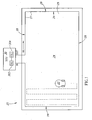
- Fig. 1 is a diagram of the system in accordance with the disclosed subject matter
- Fig. 2 is a perspective view with broken away sections of an exemplary robot for use with the system of the disclosed subject matter
- Fig. 3 is a bottom view of the robot of Fig. 2 ;
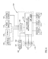
- Fig. 4 is a block diagram of the operative structure of the robot of Fig. 2 ;
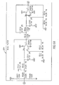
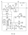
- Figs. 5A-5E form a schematic diagram of the receiver system of the robot of Fig. 2 ;
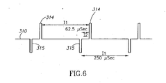
- Fig. 6 is a diagram of a waveform generated by the signal generating unit of the system of Fig. 1 ;
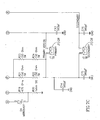
- Fig. 7A-7C form a schematic diagram of the signal generating unit of Fig. 1 ;
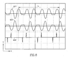
- Fig. 8 is a diagram of waveforms resulting from filtration of the received signal
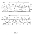
- Fig. 9 is a diagram of waveforms of the received signal illustrating negative peaks
- Fig. 10 is a diagram of the system of Fig. 1 shown with the work area separated into two sections;
- Fig. 11 is a diagram of an alternate arrangement of the system of Fig. 10 ;
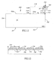
- Fig. 12 is a diagram of a system having an off perimeter charging station
- Fig. 13 is a diagram of a wave form of a received signal illustrating pulse trains and dead time of transmission.
- Fig. 14 is a diagram of the system with the work area separated into three sections.
- a system 20 that includes a robot 22, or other autonomous machine (machine), for example, a robotic lawnmower (robot and robotic lawnmower are used interchangeably in this document, with a robotic lawnmower being one type of robot or autonomous machine suitable for use in accordance with the disclosed subject matter), operating within a work area 24 or other bounded area, along a ground surface 25.
- the robot 22 is shown operating in a scanning pattern or "foot print", as shown in broken lines, that is programmed into the control unit 104, for example, the main board 150 in the microprocessor 150a thereof.
- the work area 24 is defined by a boundary 26, formed, for example, of a wire 27 (a boundary marker) arranged around the perimeter of the work area to define a perimeter wire 28 or a perimeter wire loop (perimeter wire, perimeter wire loop, and perimeter loop used interchangeably herein).
- the wire 27 is proximate to the ground surface 25, but is usually buried in the ground.
- the perimeter wire 28 is received in a signal generating unit 30.
- the signal generating unit 30 generates signals utilized by the robot 22 for multiple functions, in particular, to determine the specific location of the robot 22 within the work area 24 or outside of the work area 24, as detailed herein.
- the perimeter wire loop 28 defines a closed pathway over which the signal(s) generated by the signal generating unit 30 travel.
- the terms "signal” and “signals” are used interchangeably when referring to the electromagnetic output (e.g., electromagnetic waveforms) generated by the signal generating unit (SGU) 30.
- the signal(s) output from the signal generating unit 30, and emitted through the perimeter wire 28 are, for example, low frequency electromagnetic signals, that induce magnetic fields.
- the robot 22 receives and detects these signals, and based on this receipt, robot location with respect to the work area 24, and sections of the work area 24 (if divided into such sections), is determined.
- the wire 27 of the perimeter wire 28 is of metal or other electrically conductive metal wire.
- the wire 27 for the perimeter wire 28 may be for example, PERIMETER WIRE for the Robomower, MRK0014A, commercially available from Friendly Robotics (the trading name of the owner of this patent application) of Pardesyia 42815, Israel.
- Figs. 2-4 detail an exemplary robot 22 suitable for operation as part of the system 20.
- the robot 22 is shown is a robotic lawnmower, as its payload 119 ( Fig. 4 ) is designed for lawn mowing.
- the robot 22 may have a payload 119 designed for numerous other functions, for example, vacuum cleaning, sweeping, snow and debris removal, and the like.
- the robot 22 is similar to the robot disclosed in commonly owned U.S. Patent Application Serial No. 10/588,179 , entitled: Robot Docking Station and Robot for Use Therewith, published as U.S. Patent Application Publication No. US 2007/0142964 A1 , and PCT Patent Application No. PCT/ILOS/00119 ( WO 2005074362 ).
- the robot 22 includes docking contacts 102 (transmission parts for the transmission of energy, electricity, signals, or the like), extending forward or laterally from the front side 106 of the robot 22.
- the docking contacts 102 are typically parallel to the horizontal or ground surface. These docking contacts 102 protrude from the body 116 of the robot 22, and are described in detail in U.S. Patent Application No. 10/588,179 and PCT/IL05/00119 .
- the docking contacts 102 there are typically two docking contacts 102, at the front (or front end) end of the robot 22, electronically linked (e.g., connected or coupled, as shown in broken lines) to the control system 104 of the robot 22, and the power supply 126 (batteries and associated components).
- This electrical linkage allows for charging of the power system (not shown) once a sufficient contact is made (as determined by the control system 104, for example, there is at least a threshold voltage of, for example, as least 25 Volts, on the docking contacts 102), that allows for docking between the robot 22 and a docking station (also known as a charging station) (when a docking station is present along the perimeter wire loop 28), or when the docking station 700 is off of the perimeter loop 28 as shown, for example, in Fig. 12 .
- An exemplary docking station, suitable for use herewith, is the docking station disclosed in U.S. Patent Application Serial No. 10/588,179 and PCT/IL05/00119 , with minor modifications to
- the front wheel 110 whose axle 111 extends into a vertical rod section 112,is slideably mounted in a vertical orientation in a well 114 in the body 116 of the robot 22.
- a sensor (S1) 118 that detects wheel 110 position by detecting the position of the vertical rod section 112.
- the sensor (S1) 118 may be an electrical contact sensor, ultrasonic or light sensor, or any other position detecting sensor.
- the front wheel 110 of the robot 22, being slideably mounted in a vertical orientation, is such that when the axle 111/rod section 112, on which the front wheel 110 is mounted slides or drops downward to a predetermined level (also caused by lifting the body of the robot 20 at its front end), the rod section 112 is out of contact with the sensor (S1) 118, linked to the control system 104 ( Fig. 4 ).
- the requisite components of the control system 104 signal the drive system 151b ( Fig. 4 ) to stop movement of the robot 22.
- the robot 22 also includes cutting blades 120 driven by motors (M) 122. It also includes and a power supply 126, for example, a battery, and front 127a and rear 127b bumpers, that if depressed will stop the drive system 151b, as detailed in U.S. Pat. No. 6,443,509 .
- the front wheel 110 is passive (and typically has 360 deg. movement), and the navigation system 151a and drive system 151b control the rear wheels 128, to move and steer the robot 22.
- Fig. 4 is a block diagram showing the relationship of the components, but each of the components may be electrically linked or coupled to any other component, as would be known, for proper operation of the robot 22.
- the control system 104 includes a main board 150, and all electronics, as hardware, software and combinations thereof and other components, necessary for the robot 22 to perform all of its operations and functions (known as the main board electronics).
- the main board 150 includes one or more processors, and, for example, a microprocessor 150a, as part of the main board electronics.
- a navigation system 151 a is electrically coupled to the main board 150 and a drive system 151b is electrically coupled to the main board 150.
- the navigation system 151a and drive system 151b when combined define a movement system for the robot 22.
- the navigation system 151 a functions in the mapping operation and for directing the robot 22 inside the work area 24 based on its determined location and in accordance with the selected scanning pattern or operative mode, such as the "edge" mode, as detailed herein.
- the navigation system 151a also directs the robot 22 when outside of the work area.
- the navigation system 151a is programmable, for example, to allow for navigation in a work area 24 or the like in generally straight parallel lines, that are also substantially free of repetition. It is also programmable to other scanning patterns (for operation in the work or bounded area 24), such as saw tooth, random movement, or the like, useful in scanning a bounded area to provide coverage, and cutting over the entire work area with minimal repetition.
- the navigation system 151a works cooperatively with the drive system 151 b, that controls the rear wheels 28 of the robot 22, to move the robot 22 along a desired course for its desired operation.
- the motors (M) 122, power supply 126, and the various sensors described herein, represented by SENSORS 156, are also electrically coupled to the main board 150.
- the SENSORS 156 include electronics, known as "glue electronics” that connect the requisite sensors 118, 158, 162, 168 and any other sensors and the like to the microprocessor 150a.
- a receiver system (RS) 180 also electrically couples to the control system 104, for example, at the main board 150.
- the receiver system (RS) 180 receives and detects the perimeter signal(s) from the perimeter wire 28 of the signal generating unit 30.
- the receiver system 180 detects this signal(s) as being the boundary of the work area 24 or section thereof, in order to operate within the boundary of the work area 24 or section thereof, and work, for example in modes, such as the "edge" mode.
- the receiver system 180 also functions to convert the received signal(s) into digital data.
- the control system 104 via the electronics of the main board 150, utilizes the digital data for robot operation.
- the electronics of the main board 150 coupled with the navigation 151a and drive 151b systems, function, for example, in moving the robot 22 toward and back into the work area 24, including specific sections of the work area 24 (when the work area 24 is divided into sections, as shown for example, in Figs. 10, 11 and 14 and detailed below), from outside the work area, mapping a work area or section thereof, and moving between sections of the work area.
- the electronics of the main board 150 are programmed to cause the robot 22 to, move toward the docking station, dock in the docking station, perform the docking operations associated therewith, as detailed in U.S. Patent Application No. 10/588,179 and PCT/IL05/00119 , and other functions associated with robot 22 operation.
- the main board electronics are also programmable, such that when the robot 22 is operating with a docking station 700 ( Fig. 12 ) along the perimeter loop 28, or off of the perimeter loop 28, as shown in Fig. 12 and detailed below, the robot 22 will move toward the perimeter loop 28 to detect the perimeter signal and ultimately move toward the docking station upon detection of a docking event.
- Example docking events occur when: 1) robot operation is complete (the area within the boundary marker 28, the work area 24, has been worked); 2) the battery voltage in the robot 22 reaches (drops to) a predetermined threshold; 3) a predetermined time for robot operation has expired; or 4) a problem in the robot 22 itself is detected.
- the main board electronics are then programmed, for example, by mapping or the like, to cause the robot 22 to move toward the docking station 700 along the perimeter wire 28, also as detailed in U.S. Patent Application No. 10/588, 179 and PCT/ILOS/00119 .
- the robot 22 maps the boundary 26 by detecting the perimeter wire 28 and the proximity thereto. This mapping and detection is performed by the navigation system 151a and electronics of the main board 150 (main board electronics), as the robot 22 traverses the perimeter wire 28 and maps the work area 24, by noting its coordinates, as detailed in commonly owned U.S. Pat. No, 6,255,793 , or in accordance with navigation and detection methods disclosed in commonly owned U.S. Pat. No. 6,615,108 . U.S. Pat. No. 6,255,793 and U.S. Pat. No. 6,615,108 .
- the robot 22 notes the position of the docking station as part of its mapping, as detailed in U.S. Patent Application Serial No. 10/588,179 and PCT IL/201700119 .
- the electronics of the main bard 150 of the robot 22 are programmed to detect the position of the docking station along the perimeter wire 28 during its mapping operation or upon its initial placement in the docking station 700 ( Fig. 12 ), in both on the perimeter and off of the perimeter arrangements, and return to the docking station 700, along at least a portion of the perimeter wire 28 or wire path, when the docking station 700 is off of the perimeter wire 28, as shown for example, in Fig. 12 .
- the navigation. 151a and drive 151b systems of the robot 22 can be coordinated, and controlled by the electronics of the main board 150, to move the robot 22 to the docking station 700 (traveling along at least a portion of the perimeter wire 28). This may be, for example, in response to a docking event, detected by the electronics of the main board 150.
- the electronics of the main board 150 control operation of the robot 22 in various modes, such as an "edge" mode, where the robot 22 moves following the perimeter wire 28, by detecting a perimeter signal in the perimeter wire 28. This may occur, for example, after the robot 22 has worked the work area 24 within the perimeter wire 28.
- An exemplary edge mode is described in commonly owned U.S. Pat. No, 6,493,613 .
- U.S. Pat. No.6,493,613 U.S. Pat. No.6,493,613 .
- the payload 119 could be replaced with any other payload, such as one for vacuuming, sweeping, and the like.
- the robot 22 via the main board 150, can determine that it is in the docking station when the docking contacts 102 when carrying a voltage of approximately 25 volts or greater.
- the docking contacts 102 are also electrically coupled to the power supply 126, either directly, or through the main board 150, in order to provide recharging of the power supply 126, when the robot 22 is docked in the docking station.
- Sensors for example, voltage sensors on the docking contacts 162 are also electrically coupled to the SENSORS 156.
- obstacle sensors 168 that are electrically coupled to the SENSORS 156.
- the receiver system (RS) 180 is positioned on the robot 22 to detect the signal(s) being generated by the signal generator 30, along any point in the perimeter wire 28.
- the receiver system (RS) 180 includes a receiver (REC) 181 that is electrically coupled to a receiver unit (RU) 182.
- the receiver system (RS) 180 is electrically coupled to the control system 104, for example, to the main board 150, where data sent from the receiver system 180 is analyzed, the analysis including the determination of robot location with respect to the perimeter loop 28.
- the electronics of the main board 150 cause various operations of the robot 22 in response to the analyzed data (for robot location).
- the receiver system (RS) 180 is shown separate from the control unit 104 of the robot 22, but may be part of the control unit 104. Alternately, the receiver unit (RU) 182 may be a stand alone component, with respect to the control system 104 of the robot 22, or, for example, the receiver unit may be integrated into the main board 150.
- the receiver 181 is designed to receive the signal(s), for example, the magnetic signal(s) induced by the perimeter wire/loop 28 and the receiver unit (RU) 182 is designed to evaluate parameters including, for example, 1) an amplitude inversely proportional to the distance of the receiver 181 (receiver coil 200) from the perimeter wire/loop, as well as, 2) the state of whether the receiver (receiver coil 200) is inside or outside the work area, as defined by the perimeter loop 28.
- the magnetic signal is detected as an analog signal and converted to a digital representation, for example, a pulse.
- the receiver 182 detects the signals induced by the perimeter wire loop as an analog signals and converts the analog signal(s) to digital pulses.
- the microprocessor 150a of the control unit 104 counts the digital pulses to determine the location of the robot 22 inside or outside of the work area 24 or section thereof. This location information is then analyzed by the microprocessor 150a that signals the main board electronics, to cause the drive system 151b, and when necessary, also the navigation system 151a, to move the robot 22 accordingly.
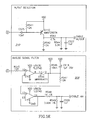
- Figs. 5A-5E shows the receiver 181 and the receiver unit 182 of the receiver system 180 in detail, in a schematic (circuit) diagram.
- the receiver 181 and the receiver unit 182 are is coordinated, for example, by being at compatible frequencies, with the signal generating unit 30, in order to determine robot 22 location as detailed below.
- the receiver unit 182 is, for example, formed of multiple components and/or circuits.
- the elements of each component or circuit, as shown in Fig. 5 when not specifically described by manufacturer code in Table 1 below include common circuit elements such as resistors (R) and capacitors (C), that are available from numerous component manufacturers and suppliers.
- CODE C500 Capacitor 0.1 ⁇ F (micro Farads) C507A, C507B Capacitor 100 pico Farads (pF) R500, R504 Resistor 39.2Kilo(K) Ohms 1% R502 Resistor 1K Ohm 1% U500A Amplifier Low Noise Operational Amplifier TL072CD Filtration Circuitry 204 COMPONENT NUMBER FROM FIGS. 5A-5E (FIG. 5 ) COMPONENT DESCRIPTION MFGR.
- CODE C525 Capacitor 10nF C527 Capacitor 1nF R543 Resistor 4.7K Ohms R541, R542 Resistor 12K Ohms R544 Resistor 3.3K Ohms Q110 Transistor MMBT2907A Additional Components from Receiver Unit 182 COMPONENT NUMBER FROM FIGS. 5A-5E (FIG. 5 ) COMPONENT DESCRIPTION MFGR.
- CODE C508 Capacitor 0.1 ⁇ F
- the receiver (REC) 181 includes a coil 200 (also known as a receiver coil), electrically coupled (for example, electrically connected) to a preamplifier 202, that is electrically coupled (for example, electrically connected) to filter circuitry 204.
- the filter circuitry 204 is electrically coupled (for example, electrically connected) to gain control circuitry 206, that is electrically coupled (for example, electrically connected) to an analog signal filter 208 and (robot) In/Out location detection circuitry 210 (also known as a detector for detecting robot location with respect to the perimeter loop 28), whose output is at CABLE_IN/OUT.
- the coil (receiver coil) 200 is, for example, a 100 micro Henry coil, for receiving the signal from the perimeter wire loop 28. While a single coil 200 is shown, multiple coils may also be used.
- the received signal is then passed to the receiver unit 182.
- the received signal is amplified in the preamplifier 202.
- the preamplified signal is then subject to filtration in the filtration circuitry 204, that is for example, an 8 KHz filter, so as to be coordinated with the frequency of the signal(s) being generated by the signal generating unit 30 (for example, the frequency of the signal generated by the signal generating unit 30 is, for example, a 4KHz signal with a 25% duty cycle, such that the 8KHz harmonics of the signal pass through the filtration circuitry 204.
- the filtration circuitry 204 may be at any other frequency, provided it is synchronized with the frequency of the signal(s) being generated by the signal generating unit 30.
- the selectable gain control circuitry 206 is for amplifying the signal(s) to ensure an optimal operation of the In/Out detection circuit 210 that follows. From the gain control circuitry 206, the signal(s) is/are fed into the analog signal filter 208, that creates a signal CABLE_AN.
- the signal CABLE_AN is proportional to the amplitude of the signal received in the coil 200 (and is inversely proportional to the distance of the coil 200 from the perimeter loop 28).
- the signal is passed to the In/Out detector circuit 210.
- the In/Out detector circuit 210 detects major peaks, positive or negative (for example, positive being above the zero lines and negative being below the zero lines in Fig. 9 ), depending on the current direction through the perimeter loop 28 from all other minor peaks in the signal.
- the threshold for a major peak as distinguished from all minor peaks programmed or programmable into the In/Out Detector circuit 210.
- the In/Out detector circuit 210 is, for example, a single transistor negative peak detector Q110, that detects the major negative peaks from the minor negative peaks.
- the receiver unit 182 would be modified slightly, for example, in the IN/Out Detector Circuit 210 such that transistor Q110 would be an NPN transistor and the positions of VDD and GND (proximate resistor R542) would be reversed. This would allow the In/Out detector 210 to function as a single transistor positive peak detector, detecting positive major peaks, similar to that for the major negative peaks, as detailed below.
- the major negative peaks in the received signals are shown, for example, by, points 505 and 506, respectively in the signal representations 501 a, 502a in Fig. 9 , detailed further below.
- the minor peaks, for example, minor negative peaks are points 507 in the signal representation 501a in Fig. 9 .
- the signal representation 502a has positive minor peaks 508).
- the PN junction of the transistor Q110, together with the capacitor C525 and a resistor R541 ( Fig. 5 ) functions as a clamping circuit.
- the signal generating unit 30 includes a signal generator (SG) 302, electrically coupled with a controller (CSG) 304.
- the signal generator 302 is, for example, a low voltage a signal generator, that induces (produces) a signal (e.g., electromagnetic or the like) for the perimeter wire loop 28.
- This low voltage signal generator is, for example, controlled by the controller 304, that is, for example, processor based.
- the controller 304 is, for example, a processor, such as a microprocessor, programmable or preprogrammed for its signal generating operations.
- the signal generator 302 drives a bi-polar square signal to the perimeter wire 28 (either by circuit components or by a microprocessor in the controller 304 typically as programmed therein).
- An exemplary bi-polar square signal is shown as represented by line 310 in Fig. 6 .
- the signal, represented by the line 310 is a unique signal, with the distance between consecutive positive pulses 314 and consecutive negative pulses 315 at intervals, also known as periods (for the signal(s)), of approximately 250 microseconds (the interval or period represented by the double headed arrow I1), while the distance between a negative pulse 314, followed by a positive pulse 314 of approximately 62.5 microseconds (being represented by the double headed arrow I2).
- the current in the perimeter wire loop 28 resulting from this unique signal (represented by the line 310) is detailed below.
- a positive and a negative pulse are spaced by a time period "TP" with an interval or frame being "4TP". Accordingly, filtration of this signal is performed with a filter of a frequency "F" of "1/(2 • TP)".
- FIG. 7A-7C An exemplary signal generator 302 for the signal generating unit 30 is shown in Fig. 7A-7C , collectively referred to hereinafter as Fig. 7 .
- the elements of each component or circuit, as shown in Fig. 7 when not specifically described by manufacturer code in Table 2 below, include common circuit elements such as resistors (R) and capacitors (C), that are available from numerous component manufacturers and suppliers.
- the schematic diagram of Fig. 7 is in accordance with standard conventions for electronic circuits.
- a catalog of the major elements of the aforementioned circuits, that form the signal generator 302 of the signal generating unit 30 is as follows from Table 2. TABLE 2 Signal Generating Unit 30 COMPONENT NUMBER FROM FIGS. 7A-7C (FIG.
- the signal is generated by a microprocessor 404 of the controller 304, and drives an H-bridge of Field Effect Transistors (FETs).
- FETs Field Effect Transistors
- This circuit generates two types of signals: the primary, along line 406, with a bridge formed of field effect transistors Q13, Q16, Q14 and Q 17, and the secondary, along line 407, with a bridge formed of field effect transistors Q13, Q16, Q15, Q18 (wire 27/28 connection at J2).
- the above-mentioned H-Bridge drives the perimeter wire loop 28 (wire 27) (connected to the H-Bridge at J1) through the capacitor C 12 (180 nano farad) and resistors R21-R24 (which creates an equivalent resistance of 150 ohm).
- the resistors R21-R24 regulate the current on the loop (so it can be approximately the same, regardless of the perimeter wire length) as well as compensate for the influence of the inductance of the perimeter wire 28 (which can become dominant in long wires).
- the H-bridge high-side is connected to a 40V power-supply 410. This power supply 410 may be another voltage, based on the current desired on the perimeter wire 28, to create a signal with a peak current amplitude of about ⁇ 200 milli Amperes.
- FIG. 1 there is shown an exemplary work area 24, bounded by the perimeter wire loop 28.
- the robot 22 may be either inside the perimeter wire loop 28 or outside of the perimeter wire loop 28, to illustrate Figs. 8 and 9 .
- the current from the signal generating unit 30 moves clockwise, around the perimeter wire loop 28, from OUT to IN, as indicated by the arrow AA.
- the coil 200 in the robot 22 is wound in a manner that signals produced by the signal generating unit 30 will be in phase.
- the current could move through the perimeter wire loop 28 counterclockwise, with all signal detection and pulse counts reversed for the robot 22 inside and outside the perimeter wire loop 28 (and the coil 200 of the robot 22 is in phase with the signal generating unit 30).
- the system will be described with the current moving clockwise around the perimeter loop 28 (in the direction of Arrow AA) and the coil 200 of the receiver 181 in the robot 22 wound accordingly, to be in phase with the signal generating unit 30.
- Fig. 8 there is shown current (along the y axis), as a function of time (along the x axis), with a time interval represented as T1.
- the current running through the perimeter loop 28 is represented by the line 420.
- the receiver 30 is such that there is a phase shift, for example, a 180° (degree) phase shift, between the signal, as received inside the perimeter wire loop 28, and outside of the perimeter wire loop 28.
- the signal for the receiving coil 200 (and the robot 22) inside the perimeter wire loop 28 is represented by the line 421, while the signal for the receiving coil 200 (and the robot 22) outside the perimeter loop 28 is represented by the line 422.
- Line 422 is a 180° (degree) phase shift from line 421.
- Lines 421 and 422 represent received signals for the current being passed through the perimeter wire 28, such as the current for the signal shown in Fig. 7 , represented by the line 310.
- Fig. 9 shows the time interval T1, for the filtered signal and the CABLE_IN/OUT signal (at the output U503B, from Fig. 5 ) in the cases that the receiver coil 200 of the robot 22 is outside the perimeter wire loop 28 (the filtered signal is 501 a and the corresponding CABLE_IN/OUT signal is line 501b, as converted into pulses), and inside the perimeter loop 28 (the filtered signal is 502a and the corresponding CABLE_IN/OUT signal is line 502b, as converted into pulses).
- Applying negative peak detection as performed by the negative peak detector Q110 shown and described for Fig. 5 above, each major negative peak of lines 501a and 502a results in a pulse 501bx, 502bx in corresponding lines 501b and 502b, respectively.
- Peaks of the signal represented by lines 501a and 502a respectively, in particular, the major negative peaks below the "0" line, also known and referred to as dips, and indicated by 505 and 506 in lines 501a and 502a, respectively are detected.
- the frequency and accordingly, the major negative peaks are double the frequency of major negative peaks for the robot 22 outside of the perimeter wire loop 28, represented by lines 501a, 501b.
- the pulses 501bx, 502bx of lines 501b or 502b are input into the control system 104 of the robot 22, for example, as data, such as digital data.
- the control system 104 via the electronics of the main bard 150, processes this data to determine robot 22 location inside or outside of the perimeter loop 28 and control robot 22 operation.
- FIG. 10 details another system 600.
- This system 600 employs the robot 22 in a work area 24, with the work area 24 divided into multiple sections or plots, as would be typical with a lawn, garden or the like.
- This system 600 with the work area 24 divided into multiple sections allows for the operation of a robot 22, or alternately, several robots (or guided vehicles) operating at the same time (each vehicle in a different section or plot), in different sections or plots.
- the system 600 allows a detection of various parts on the perimeter loop 28, as well as the detection of a border or boundary line between sections of a work area 24.
- Fig. 10 shows the work area 24 divided into two sections, Section 1 601, and Section 2 602.
- the signal generating unit 30 includes a switch 606 or the like, whose default or primary connection is along the outer perimeter 608 of the work area 24, formed by dashed lines 610 and dotted lines 611.
- a wire 614 dividing the work area 24 into Section 1 601 and section 2 is represented as the solid line, and is the secondary connection for the switch 606.
- the signal generating unit 30 sends the signal(s) through the primary connection of lines 610 and 611 and the secondary connection of lines 611 and 614, based upon the position of the switch 606.
- the switch 606 is, for example, programmed to alternate between the two positions at regular intervals. For example, the switch 606 is programmed to alternate between the two positions, resulting in a signal sent through the primary connection of lines 610 and 611 for approximately 48 milliseconds (ms) and through the secondary connection of lines 610 and 614 for approximately 2 ms.
- the dashed-line section 610 receives current 100% of the time the signal(s) is/are being generated by the signal generating unit 30. Similarly, the dotted line section 611 receives current 96% of the time the signal(s) is/are being generated, while line 614 receives current 4% of the time signals are being generated.
- the receiver system 180 in the robot 22 measures the period of transmissions in each frame (where a frame is, for example, a 50 millisecond (ms) time interval or period).
- the receiver system 180 detects the dominant signal, that is emitted from the nearest wire 26 of the system 600.
- the robot via the control system 104 (the main board electronics), determines the location of the robot 22, and for example, can determine if the robot 22 is in Section 1 601, Section 2 602, or outside Section 1 601 or outside Section 2 602.
- the robot 22, as programmed in the control system 104 (the main board electronics) can operate accordingly, for example, scanning differently based on the specific section in which the robot 22 is operating, moving into or out the requisite sections or moving along the wire 26, following it.
- the robot 22 can drive along the perimeter wire 28 (formed of the dashed line 610) from Section 1 601, until Section 2 602 is detected. The robot 22 will then turn inside Section 2 602, and begin to scan Section 2 602.
- One method or process for detecting the transmission periods for the signal(s) in each wire 610, 611, 614 is by counting the pulses of the major peak, for example the negative major peak detector described for the microprocessor 150a of the main board electronics of the robot 22, above (shown in Fig. 4 ) at each frame of time (for example, approximately 50 ms).
- the major peak for example the negative major peak detector described for the microprocessor 150a of the main board electronics of the robot 22, above (shown in Fig. 4 ) at each frame of time (for example, approximately 50 ms).
- wire 610 receives current 100% of the time, so that 100% of the pulses from the signal (generated by the signal generating unit 30) over a 50 millisecond time frame is 400 pulses, for the robot 22 being inside Section 1 601. Since there is a phase shift of the received signal outside of the perimeter loop 28, from the phase of the received signal inside the perimeter loop 28, the received signal is inverted, reducing the number of major negative peaks by one-half outside of the perimeter wire loop 28, as shown in Fig. 9 . Accordingly, with the robot 22 outside of Section 1 601, the received signal for the frame would result in a pulse count of 200 pulses, the decrease of pulses in accordance with the above-described phase shift.
- wire 611 receives current 96% of the time, so that 96% of the pulses from the signal(s) (generated by the signal generating unit 30) over a 50 millisecond (ms) time frame is 384 pulses, for the robot 22 being inside Section 2 602. Since there is phase shift, as detailed above, outside of the perimeter wire loop 28, the robot 22 being outside of Section 2 602 would be 192 pulses, the decrease of pulses in accordance with the phase shift.
- Fig. 11 shows a system 600' that is similar to Fig. 10 , except that Section 1 601 and Section 2 602 are reoriented based on the position of the signal generating unit 30 and the switch 606 is separate (outboard) from the signal generating unit 30.
- This switch 606 may be controlled by a controller 630 (also a remote controller) electronically linked to the switch 606 by wired or wireless links, or combinations thereof.
- Fig. 12 shows an example of a system 699 using the above described negative peak detection with an off-perimeter charging station 700.
- the charging station 700 is placed outside the lawn or work area 24, off of the perimeter loop 28.
- the work area 24 and perimeter loop 28 are represented by line segments 702, 703, 704, 705a, 705b.
- An off perimeter path 712 from the work area 24 to the charging station 700 is represented by line segments 714, 715. These segments 714, 715 extend from the charging station 700 to the junction 710 and connect to segments 702 and 705b respectively.
- a dashed line segment 718 extends from the node 708 to the charging station 700, specifically, to a switch 720 in the charging station 700.
- the switch 720 is programmed to alternate between two positions, resulting in a signal sent through the primary connection of segments 714, 702, 703, 704, 705a and 718 for approximately 48 milliseconds (ms) and through the secondary connection of segments 715, 705b and 718 for approximately 2 ms.
- the dashed-line segment 718 receives current 100% of the time the signal(s) is/are being generated by the signal generating unit 30.
- the line formed of segments 714, 702, 703, 704 and 705a receives current 96% of the time the signal(s) is/are being generated, while segments 705b and 715 receive current 4% of the time signals are being generated.
- the robot 22 moves to the junction 710 during the "edge" mode, following along the perimeter wire 28 of the work area 24, and then slows down (as programmed into the control unit 140, the main board electronics) upon receiving a count of pulses of 100%, for example 400 for one time interval or period of a 50 ms frame) and continue to the charging station 700.
- the robot 22 Upon departure from the charging station 700, the robot 22 will reverse until it meets the 96% signal at the junction 710 and than turns left, to move along the segment 705b, and the remainder of the perimeter loop 28 (formed of segments 705a, 704, 703 and 702), to operate in the work area 24.
- the pulses also allow for the robot 22 to determine its location within the work area 24, along the off perimeter path 712 to the docking station 700, and outside of the work area 24.
- the aforementioned pulse counting method also allows the robot 22 to detect a border or boundary line 26 during scanning, while the robot travels inside the work area 24 surrounded by the perimeter loop 28.
- Fig. 13 shows the received signal at the output of the negative peak detector Q110, detailed above, also known as a dip detector, as a line 750, when the robot 22 is approaching the border line 614 between Section 1 601 and Section 2 602, as shown in Figs. 10 and 11 .
- the received signal of line 750 is, for example, expressed in terms of pulses in pulse trains 752 (corresponding to the pulses of lines 501b and 502b) and "dead time," when pulses are not being transmitted (a signal is not being passed through the requisite wire section). For example, at line 614, pulses are being transmitted 96% of the "dead time".
- the pulses are smoothed over, resulting in smoothed portions 754 of the signal, with the "dead time” resulting in major negative peaks or dips 756.
- the major negative peaks or dips 756 in the signal, for each frame (interval, or time period) (Tx), are analyzed in the microprocessor 150a of the main board electronics, like the negative peaks of Fig. 9 , as detailed above.
- Fig. 14 shows a system 800 similar to the systems 20, 600 and 600', except the work area 24 is divided into three sections, Section 1 801, Section 2 802 and Section 3 803.
- Each switch 806, 807 has a default or primary connection is along the outer perimeter 808 of the work area 24, represented by dashed lines 810, dotted lines 811, and dash-dot lines 812.
- Wires, represented by solid lines 814 and 815, respectively, divide Section 1 801 from Section 2 802, and Section 2 802 from Section 3 803, are the secondary connections for the switches 806, 807.
- the signal generating unit 30 sends the signal(s) through the primary connection of lines 810, 811 and 812, the secondary connection of line 814 and the tertiary connection of line 815, based upon the position of the switches 806, 807.
- the switches 806, 807 for example, are programmed to be synchronized, such that the switch 807 connects to line 815 only when the switch 806 connects to line 811.
- the switches 806, 807 are programmed to alternate between the two positions, resulting in a signal sent through the primary connection of lines 810, 811 and 812 for approximately 46 milliseconds (ms), through the secondary connection of lines 810, 811 and 815 for approximately 2 ms, and through the tertiary connection of lines 810 and 814 for approximately 2 ms.
- the dashed-line section 810 receives current 100% of the time the signal(s) is/are being generated by the signal generating unit 30. Similarly, the dotted line section 811 receives current 96% of the time the signal(s) is/are being generated, and the dash-dot line 812 receives current 92% of the time the signal(s) is/are being generated.
- the receiver system 180 in the robot 22 measures the period of signal transmissions in each frame (where a frame is, for example, 50 millisecond time interval or period). The receiver system 180, recognizes the dominant signal and detects the nearest wire 26. Once this wire 26 is detected, the robot 22, via the control system 104 (main board electronics), determines the location of the robot 22, in accordance with that detailed above, and, for example, can determine if the robot 22 is in Section 1 801, Section 2 802, Section 3 803, or outside each of these sections. The robot 22, as programmed in the control system 104, and can operate accordingly, for example, scanning differently based on the specific section in which the robot 22 is operating, moving into or out the requisite sections 801-803 or moving along the perimeter wire 28, following it.
- the robot 22 can move along the perimeter wire 28 (formed of the dashed line 810) from Section 1 801, until Section 2 802 is detected. The robot 22 will then turn inside Section 2 802, and begin to scan Section 2 802.
- One method or process for detecting the transmission periods for the signal(s) in each wire represented by the respective lines 810, 811, 812, 814 and 815, by counting the pulses of the negative-peak detector described for the control system 104 (main board electronics) of the robot 22, above (shown in Fig. 5 ) at each frame of time (for example, approximately 50 ms).
- each section of the perimeter wire loop 28 results in a unique count.
- the location of the robot 22 is determined from the requisite unique count.
- the systems including systems 20, 600, 600', 699, 800 and embodiments thereof, as described above, are scaleable. They may be applied to as many sections of a work area 24 as desired in accordance with that detailed above.
- an aspect of the invention provides a system which is employed for identifying a position (location) of a receiving element inside an area surrounded by a wire loop, along the perimeter (a perimeter wire loop), of a work area or other bounded area.
- the system can determine whether the receiver is inside or outside the loop, and evaluate its distance from the perimeter wire.
- An aspect of the invention provides a system for detecting the position of a machine, comprising: means for transmitting signals along at least two defined pathways; and, means for analyzing the location of the machine based on the transmitted signals
- a system for determining information relating to the position of an object relative to an area including signal generating means for applying an input signal to the boundary element, receiving means associated with the object for receiving an output signal from the boundary element, detector means for analysing the received signal and determining information relating to the position of the object relative to the area.
- the boundary element defines an inner area, the detector means determining whether or not the object is within the inner area.
- the boundary element may define a substantially closed inner area.
- the input signal may comprise a plurality of pairs of pulses, and preferably the pulses are of different phase.
- the detector means is preferably adapted to determine peaks in the received signal having an amplitude greater than a predetermined threshold and may be adapted to determine only peaks in the received signal having a specific phase.
- the detector may be adapted to detect peaks in the signal and to count the number of detected peaks, the number of detected peaks providing information relating to the position of an object relative to the area.
- An aspect of the invention further provides a boundary system for example for use in a system described herein, the boundary system including a boundary element, and a signal generating means for applying a signal to the boundary system.
- a further aspect of the invention provides an object (for example being an object the position of which relative to an area is to be determined) including a receiving means for receiving or sensing an output signal (for example a magnetic field) from a boundary element, and further including means for generating a signal for analysis to determine information relating to the position of the object relative to the area.
- the object may for example comprise a robot.
- a further aspect of the invention provides a processing means for processing signals obtained from the receiver of the object and for determining information relating to the position of the object relative to an area.
- the invention further provides a method for determining information relating to the position of an object relative to an area, the area being defined by a boundary element, the method including applying an input signal to the boundary element, receiving an output signal from the boundary element, analysing the received signal and determining information relating to the position of the object relative to the area.
- the invention further provides a system for detecting information relating to the position of an object, comprising: means for transmitting signals along at least two defined pathways, and means for analyzing the location of the machine based on the transmitted signals.
- the system further comprises a plurality of boundary elements the plurality of boundary elements defining a plurality of areas, the arrangement being such that the signal generating means selectively applies signals to one or more of the boundary elements of the plurality of boundary elements.
- the system may include a switch for selectively applying the signal to one or more of the boundary elements of the plurality of boundary elements.
- a boundary element is common to more than one area.
- the reference relates to peaks having an amplitude above a predetermined threshold.
Landscapes
- Physics & Mathematics (AREA)
- Engineering & Computer Science (AREA)
- General Physics & Mathematics (AREA)
- Radar, Positioning & Navigation (AREA)
- Remote Sensing (AREA)
- Life Sciences & Earth Sciences (AREA)
- Environmental Sciences (AREA)
- Electromagnetism (AREA)
- Aviation & Aerospace Engineering (AREA)
- Automation & Control Theory (AREA)
- Control Of Position, Course, Altitude, Or Attitude Of Moving Bodies (AREA)
Claims (25)
- Système (20) destiné à déterminer des informations concernant la position d'un objet (22) par rapport à une zone, la zone étant définie par un élément de délimitation (26), l'élément de délimitation (26) comportant une boucle de fil (28) et définissant une zone intérieure (24) à l'intérieur de la boucle, le système incluant :des moyens de génération de signaux (30) pour appliquer un signal d'entrée à la boucle de fil,des moyens de réception (180) associés à l'objet (22) pour recevoir un signal de sortie provenant de la boucle de fil (26) qui inclut au moins une impulsion positive et au moins une impulsion négative sur une période prédéterminée, caractérisé en ce que le système inclut en outre :des moyens de détection (104) pour analyser le signal reçu et déterminer un nombre de pics détectés (505), le système incluant en outre des moyens pour déterminer si oui ou non l'objet est dans la zone intérieure en fonction du nombre de pics détectés sur une période prédéterminée.
- Système selon la revendication 1, dans lequel le signal d'entrée comporte une pluralité de paires d'impulsions.
- Système selon la revendication 2, dans lequel les impulsions de la paire sont de phase différente.
- Système selon l'une quelconque des revendications 1 à 3, dans lequel les moyens de détection (104) sont adaptés pour déterminer des pics dans le signal reçu ayant une amplitude supérieure à un seuil prédéterminé.
- Système selon l'une quelconque des revendications 1 à 4, dans lequel les moyens de détection sont adaptés pour déterminer uniquement des pics dans le signal reçu ayant une phase particulière.
- Système selon l'une quelconque des revendications 1 à 5, comportant en outre une pluralité d'éléments de délimitation (26), la pluralité d'éléments de délimitation définissant une pluralité de zones, la disposition étant telle que les moyens de génération de signaux (30) appliquent sélectivement des signaux à un ou plusieurs des éléments de délimitation de la pluralité d'éléments de délimitation (26).
- Système selon l'une quelconque des revendications 1 à 6, dans lequel les moyens de détection (104) sont configurés pour convertir les pics négatifs détectés en données numériques.
- Système selon l'une quelconque des revendications 1 à 7, comportant de plus : un robot (22), le robot étant ledit objet et incluant les moyens de réception (180) et des moyens de détection (104).
- Système selon la revendication 8, dans lequel le robot comporte de plus :un processeur (150) en communication électronique avec les moyens de détection pour recevoir des données numériques associées aux pics détectés, le processeur étant adapté pour :déterminer l'emplacement du robot par rapport à l'élément de délimitation (26) en fonction des données numériques.
- Système selon la revendication 9, dans lequel le processeur (150) est adapté pour compter le nombre d'impulsions et comparer le nombre compté d'impulsions à des décomptes d'impulsions prédéterminés pour déterminer l'emplacement du robot.
- Procédé de détermination de la position d'un objet (22) par rapport à une zone (24), le procédé comportant les étapes consistant à :fournir un élément de délimitation (26) définissant la zone (24), l'élément de délimitation (26) comportant une boucle de fil (28) et définissant une zone intérieure (24) dans la boucle, etfournir un objet (22) et des moyens de réception (180) associés à l'objet, le procédé comportant en outre les étapes consistant à appliquer un signal d'entrée à la boucle de fil,recevoir un signal de sortie provenant de la boucle de fil sur les moyens de réception (180) qui inclut au moins une impulsion positive et au moins une impulsion négative sur une période prédéterminée, caractérisé en ce que le procédé inclut les étapes consistant à analyser le signal reçu, compter un nombre de pics détectés (505), et déterminer si oui ou non l'objet est à l'intérieur de la zone intérieure (24) en fonction du nombre de pics détectés sur une période prédéterminée.
- Procédé selon la revendication 11, incluant la détermination du nombre de pics ayant une amplitude supérieure à un seuil prédéterminé.
- Procédé selon la revendication 11 ou la revendication 12, incluant la détermination du nombre de pics ayant une phase particulière.
- Procédé selon l'une quelconque des revendications 11 à 13, incluant l'application sélective d'un signal à un ou plusieurs éléments de délimitation (26) d'une pluralité d'éléments de délimitation.
- Procédé selon l'une quelconque des revendications 11 à 14, comportant les étapes consistant à :fournir une première boucle de fil incluant une première partie et une deuxième partie,fournir une seconde boucle de fil incluant la deuxième partie et une troisième partie,délivrer un signal sur une première boucle et délivrer le signal sur une seconde boucle à un intervalle de délivrance prédéterminé, la délivrance du signal étant telle qu'au moins la première partie reçoit toujours le signal délivré, la deuxième et la troisième partie reçoivent le signal délivré en fonction de l'intervalle de délivrance prédéterminé,recevoir le signal,convertir le signal en impulsions,compter les impulsions pendant un intervalle de réception prédéterminé, etanalyser les impulsions comptées pendant l'intervalle de réception prédéterminé par rapport à des décomptes d'impulsions prédéterminés pendant l'intervalle de réception prédéterminé en fonction de l'intervalle de délivrance prédéterminé pour déterminer l'emplacement du récepteur.
- Procédé selon la revendication 15, dans lequel le signal inclut une période d'au moins une impulsion positive et d'au moins une impulsion négative sur l'intervalle de délivrance prédéterminé.
- Procédé selon l'une quelconque des revendications 11 à 16, dans lequel la détection de pics dans le signal inclut l'étape consistant à :détecter les pics négatifs majeurs dans le signal, etla conversion du signal en impulsions inclut la conversion des pics négatifs majeurs détectés dans le signal, en impulsions.
- Procédé selon l'une quelconque des revendications 11 à 17, dans lequel ledit objet est un robot (22) incluant :lesdits moyens de réception (180) pour recevoir le signal de sortie,des moyens de détection (104) pour détecter des pics dans le signal et convertir les pics dans le signal en impulsions, et,un processeur (150) pour compter les impulsions et analyser les impulsions comptées par rapport à des décomptes d'impulsions prédéterminés pour déterminer l'emplacement du robot par rapport à l'élément ou aux éléments de délimitation (26).
- Robot (22) adapté pour une utilisation dans un système (20) selon l'une quelconque des revendications 1 à 10 en tant que robot ou objet susmentionné, ou pour une utilisation dans un procédé selon la revendication 18 en tant qu'objet (22) susmentionné, le robot (22) incluant lesdits moyens de réception et lesdits moyens de détection, dans lequel lesdits moyens de réception (180) sont adaptés pour recevoir un signal de sortie provenant de la boucle de fil (20) qui inclut au moins une impulsion positive et au moins une impulsion négative sur une période prédéterminée, caractérisé en ce que les moyens de détection (104) sont adaptés pour analyser le signal reçu et déterminer un nombre de pics détectés (505), et en ce que le robot inclut des moyens adaptés pour déterminer si le robot (22) est à l'intérieur d'une zone (24) définie par les éléments de délimitation (26) en fonction du nombre de pics détectés.
- Robot selon la revendication 19, dans lequel lesdits moyens de réception (180) sont adaptés pour recevoir un signal transmis à partir de la boucle de fil (26), le signal transmis incluant au moins une impulsion positive et au moins une impulsion négative sur un intervalle prédéterminé.
- Robot selon la revendication 19 ou la revendication 20, dans lequel les moyens de détection (104) sont adaptés pour détecter des pics ayant une amplitude supérieure à un seuil prédéterminé, ou ayant une phase particulière.
- Robot selon la revendication 21, dans lequel les moyens de détection (104) sont adaptés pour détecter des pics négatifs.
- Robot selon la revendication 21, dans lequel les moyens de détection sont adaptés pour détecter des pics positifs.
- Robot selon la revendication 22, dans lequel le détecteur est configuré pour convertir les pics négatifs détectés en données numériques.
- Robot selon la revendication 24, incluant des moyens pour déterminer l'emplacement du robot par rapport à l'élément de délimitation (26) en comptant les impulsions dans les données, et comparer les impulsions comptées à des décomptes d'impulsions prédéterminés pour déterminer l'emplacement du robot (22).
Priority Applications (1)
| Application Number | Priority Date | Filing Date | Title |
|---|---|---|---|
| EP10189720.5A EP2296005B1 (fr) | 2006-09-29 | 2007-09-28 | Procédé et système de détermination de l'emplacement d'un véhicule |
Applications Claiming Priority (2)
| Application Number | Priority Date | Filing Date | Title |
|---|---|---|---|
| US84809806P | 2006-09-29 | 2006-09-29 | |
| US11/861,978 US8046103B2 (en) | 2006-09-29 | 2007-09-26 | System and method for determining the location of a machine |
Related Child Applications (1)
| Application Number | Title | Priority Date | Filing Date |
|---|---|---|---|
| EP10189720.5 Division-Into | 2010-11-02 |
Publications (2)
| Publication Number | Publication Date |
|---|---|
| EP1906205A1 EP1906205A1 (fr) | 2008-04-02 |
| EP1906205B1 true EP1906205B1 (fr) | 2013-01-09 |
Family
ID=38959680
Family Applications (2)
| Application Number | Title | Priority Date | Filing Date |
|---|---|---|---|
| EP07253861A Not-in-force EP1906205B1 (fr) | 2006-09-29 | 2007-09-28 | Procédé et système de détermination de l'emplacement d'un véhicule |
| EP10189720.5A Not-in-force EP2296005B1 (fr) | 2006-09-29 | 2007-09-28 | Procédé et système de détermination de l'emplacement d'un véhicule |
Family Applications After (1)
| Application Number | Title | Priority Date | Filing Date |
|---|---|---|---|
| EP10189720.5A Not-in-force EP2296005B1 (fr) | 2006-09-29 | 2007-09-28 | Procédé et système de détermination de l'emplacement d'un véhicule |
Country Status (2)
| Country | Link |
|---|---|
| US (2) | US8046103B2 (fr) |
| EP (2) | EP1906205B1 (fr) |
Families Citing this family (144)
| Publication number | Priority date | Publication date | Assignee | Title |
|---|---|---|---|---|
| KR20070112106A (ko) * | 2004-11-23 | 2007-11-22 | 에스.씨. 존슨 앤드 선, 인코포레이티드 | 바닥표면의 청소와 함께 공기정화를 제공하는 장치 및 방법 |
| ES2707155T3 (es) | 2006-03-17 | 2019-04-02 | Irobot Corp | Confinamiento de robot |
| US8046103B2 (en) * | 2006-09-29 | 2011-10-25 | F Robotics Acquisitions Ltd. | System and method for determining the location of a machine |
| DE102009001900A1 (de) * | 2008-10-20 | 2010-04-22 | Robert Bosch Gmbh | Verfahren und System zur Arbeitsbereichserkennung eines mobilen Arbeitsgerätes |
| US8740538B2 (en) | 2009-04-10 | 2014-06-03 | Symbotic, LLC | Storage and retrieval system |
| GB0909148D0 (en) * | 2009-05-28 | 2009-07-01 | F Robotics Acquisitions Ltd | Localisation system |
| US8774970B2 (en) | 2009-06-11 | 2014-07-08 | S.C. Johnson & Son, Inc. | Trainable multi-mode floor cleaning device |
| DE102010028251A1 (de) | 2010-04-27 | 2011-10-27 | Robert Bosch Gmbh | Verfahren zum Erkennen eines Arbeitsbereichs sowie ein Gerät hierfür |
| US8744626B2 (en) * | 2010-05-27 | 2014-06-03 | Deere & Company | Managing autonomous machines across multiple areas |
| US8433468B2 (en) * | 2010-07-28 | 2013-04-30 | Deere & Company | Robotic mower home finding system |
| US20120029752A1 (en) * | 2010-07-28 | 2012-02-02 | Johnson David A | Robotic Mower Stuck Detection System |
| US8392044B2 (en) * | 2010-07-28 | 2013-03-05 | Deere & Company | Robotic mower boundary sensing system |
| US10822168B2 (en) | 2010-12-15 | 2020-11-03 | Symbotic Llc | Warehousing scalable storage structure |
| US9008884B2 (en) | 2010-12-15 | 2015-04-14 | Symbotic Llc | Bot position sensing |
| US9475649B2 (en) | 2010-12-15 | 2016-10-25 | Symbolic, LLC | Pickface builder for storage and retrieval systems |
| US8694152B2 (en) | 2010-12-15 | 2014-04-08 | Symbotic, LLC | Maintenance access zones for storage and retrieval systems |
| EP2502482B1 (fr) * | 2011-03-23 | 2013-05-22 | Fabrizio Bernini | Tondeuse |
| EP2502481B1 (fr) * | 2011-03-23 | 2013-02-13 | Fabrizio Bernini | Tondeuse |
| DK2703925T3 (da) * | 2011-04-28 | 2021-05-10 | Positec Power Tools Suzhou Co Ltd | Automatisk arbejdssystem, automatisk gangindretning og styrefremgangsmåde dertil |
| EP2545758B1 (fr) * | 2011-07-14 | 2013-10-30 | Fabrizio Bernini | Appareil pour découpage d'herbe |
| CN102890505B (zh) * | 2011-07-18 | 2014-11-26 | 苏州宝时得电动工具有限公司 | 边界系统 |
| US9471063B2 (en) * | 2011-08-11 | 2016-10-18 | Chien Ouyang | Robotic lawn mower with network sensors |
| TWI622540B (zh) | 2011-09-09 | 2018-05-01 | 辛波提克有限責任公司 | 自動化儲存及取放系統 |
| EP2574225B1 (fr) * | 2011-09-30 | 2013-09-11 | Fabrizio Bernini | Appareil pour couper l'herbe |
| CN103197672A (zh) * | 2012-01-05 | 2013-07-10 | 苏州宝时得电动工具有限公司 | 边界信号识别方法及其边界系统 |
| CN102681545B (zh) * | 2012-05-30 | 2015-05-20 | 宁波市德霖机械有限公司 | 一种用于控制自动设备的工作区域界定和引导的方法及其系统 |
| CN103488172B (zh) * | 2012-06-13 | 2016-10-05 | 苏州宝时得电动工具有限公司 | 自动工作系统及其控制方法 |
| ES2610755T3 (es) | 2012-08-27 | 2017-05-03 | Aktiebolaget Electrolux | Sistema de posicionamiento de un robot |
| EP2741160B1 (fr) * | 2012-12-07 | 2016-10-12 | Viking GmbH | Procédé de commande d'une tondeuse automobile |
| CN103869813B (zh) * | 2012-12-14 | 2017-02-01 | 苏州宝时得电动工具有限公司 | 自动工作系统 |
| EP2939508B1 (fr) | 2012-12-28 | 2021-05-19 | Positec Power Tools (Suzhou) Co., Ltd | Système de tondeuse automatique |
| CN105009014B (zh) * | 2013-02-21 | 2017-09-01 | 胡斯华纳有限公司 | 改进的机器人作业工具 |
| TWI594933B (zh) | 2013-03-15 | 2017-08-11 | 辛波提克有限責任公司 | 自動化貯藏及取放系統 |
| TWI642028B (zh) | 2013-03-15 | 2018-11-21 | 辛波提克有限責任公司 | 具有整合式受保護的人員接觸區及遠端漫遊機關機之運送系統及自動化儲存和取放系統 |
| EP2972627B1 (fr) | 2013-03-15 | 2019-05-08 | MTD Products Inc | Système de travail mobile autonome comprenant une station de base à réflectivité variable |
| KR102265424B1 (ko) | 2013-03-15 | 2021-06-15 | 심보틱 엘엘씨 | 통합 보안 직원 액세스 구역 및 원격 로버 조업 중지를 구비한 자율화된 저장 및 인출 시스템 |
| GB201306437D0 (en) * | 2013-04-09 | 2013-05-22 | F Robotics Acquisitions Ltd | Domestic robotic system and robot therfor |
| CN105101855A (zh) | 2013-04-15 | 2015-11-25 | 伊莱克斯公司 | 具有伸出的侧刷的机器人真空吸尘器 |
| EP2986192B1 (fr) | 2013-04-15 | 2021-03-31 | Aktiebolaget Electrolux | Dispositif de nettoyage sous vide robotisé |
| CN104252175B (zh) * | 2013-06-28 | 2017-09-22 | 苏州宝时得电动工具有限公司 | 自动工作系统及其抗信号干扰的方法 |
| ITMI20131252A1 (it) | 2013-07-25 | 2015-01-26 | Fabrizio Bernini | Apparecchiatura di lavorazione di un¿area limitata |
| CN105705441B (zh) | 2013-09-13 | 2018-04-10 | 西姆伯蒂克有限责任公司 | 自主运输车、存储和取回系统及在该系统内传递拣选面的方法 |
| EP3082537B1 (fr) | 2013-12-19 | 2020-11-18 | Aktiebolaget Electrolux | Dispositif de nettoyage robotisé et procédé de reconnaissance de point de repère |
| CN105792721B (zh) | 2013-12-19 | 2020-07-21 | 伊莱克斯公司 | 以螺旋样式移动的带侧刷的机器人真空吸尘器 |
| JP6638987B2 (ja) | 2013-12-19 | 2020-02-05 | アクチエボラゲット エレクトロルックス | 回転側面ブラシの適応速度制御 |
| EP3084539B1 (fr) | 2013-12-19 | 2019-02-20 | Aktiebolaget Electrolux | Priorisation de zones de nettoyage |
| WO2015090402A1 (fr) * | 2013-12-19 | 2015-06-25 | Aktiebolaget Electrolux | Dispositif de nettoyage robotisé à fonction d'enregistrement de périmètre |
| KR102099495B1 (ko) | 2013-12-19 | 2020-04-09 | 에이비 엘렉트로룩스 | 로봇 청소 장치가 장애물에 올라가는 것의 감지 |
| CN105849660B (zh) | 2013-12-19 | 2020-05-08 | 伊莱克斯公司 | 机器人清扫装置 |
| KR102116595B1 (ko) | 2013-12-20 | 2020-06-05 | 에이비 엘렉트로룩스 | 먼지통 |
| KR101537623B1 (ko) * | 2014-01-29 | 2015-07-17 | 엘지전자 주식회사 | 잔디 깎기 로봇 및 그 제어 방법 |
| US9740210B2 (en) | 2014-01-30 | 2017-08-22 | Husqvarna Ab | Robotic working tool system with a boundary wire |
| WO2015153109A1 (fr) | 2014-03-31 | 2015-10-08 | Irobot Corporation | Robot mobile autonome |
| DE102014104619A1 (de) * | 2014-04-02 | 2015-10-08 | Claas Agrosystems Kgaa Mbh & Co. Kg | Planungssystem und Verfahren zur Planung einer Feldbearbeitung |
| WO2016005012A1 (fr) | 2014-07-10 | 2016-01-14 | Aktiebolaget Electrolux | Procédé de détection d'une erreur de mesure dans un dispositif de nettoyage robotisé |
| JP6443897B2 (ja) | 2014-09-08 | 2018-12-26 | アクチエボラゲット エレクトロルックス | ロボット真空掃除機 |
| EP3190938A1 (fr) | 2014-09-08 | 2017-07-19 | Aktiebolaget Electrolux | Aspirateur robotisé |
| JP2017535279A (ja) | 2014-09-23 | 2017-11-30 | 宝時得科技(中国)有限公司Positec Technology (China) Co.,Ltd. | 自動移動ロボット |
| US9510505B2 (en) | 2014-10-10 | 2016-12-06 | Irobot Corporation | Autonomous robot localization |
| US9516806B2 (en) | 2014-10-10 | 2016-12-13 | Irobot Corporation | Robotic lawn mowing boundary determination |
| JP6307748B2 (ja) * | 2014-10-21 | 2018-04-11 | 本田技研工業株式会社 | 自律走行作業車の制御装置 |
| US9804594B2 (en) | 2014-11-07 | 2017-10-31 | Clearpath Robotics, Inc. | Self-calibrating sensors and actuators for unmanned vehicles |
| EP3230814B1 (fr) | 2014-12-10 | 2021-02-17 | Aktiebolaget Electrolux | Utilisation d'un capteur laser pour la détection d'un type de sol |
| WO2016091312A1 (fr) * | 2014-12-11 | 2016-06-16 | Husqvarna Ab | Navigation améliorée pour outil de travail robotique |
| CN107072454A (zh) | 2014-12-12 | 2017-08-18 | 伊莱克斯公司 | 侧刷和机器人吸尘器 |
| US9420741B2 (en) | 2014-12-15 | 2016-08-23 | Irobot Corporation | Robot lawnmower mapping |
| KR102339531B1 (ko) | 2014-12-16 | 2021-12-16 | 에이비 엘렉트로룩스 | 로봇 청소 장치를 위한 경험-기반의 로드맵 |
| JP6532530B2 (ja) | 2014-12-16 | 2019-06-19 | アクチエボラゲット エレクトロルックス | ロボット掃除機の掃除方法 |
| US9538702B2 (en) * | 2014-12-22 | 2017-01-10 | Irobot Corporation | Robotic mowing of separated lawn areas |
| JP6014192B1 (ja) * | 2015-03-27 | 2016-10-25 | 本田技研工業株式会社 | 無人作業車の制御装置 |
| US11099554B2 (en) | 2015-04-17 | 2021-08-24 | Aktiebolaget Electrolux | Robotic cleaning device and a method of controlling the robotic cleaning device |
| EP3302020B1 (fr) | 2015-05-27 | 2020-04-08 | MTD Products Inc | Groupe de couteaux pour tondeuse autonettoyant |
| USD794089S1 (en) | 2015-06-05 | 2017-08-08 | Mtd Products Inc | Wheel |
| USD760806S1 (en) | 2015-06-05 | 2016-07-05 | Mtd Products Inc | Robotic mower |
| USD758455S1 (en) | 2015-06-05 | 2016-06-07 | Mtd Products Inc | Robotic mower body |
| USD797530S1 (en) | 2015-06-05 | 2017-09-19 | Mtd Products Inc | Blade |
| US11115798B2 (en) | 2015-07-23 | 2021-09-07 | Irobot Corporation | Pairing a beacon with a mobile robot |
| US10034421B2 (en) | 2015-07-24 | 2018-07-31 | Irobot Corporation | Controlling robotic lawnmowers |
| WO2017036532A1 (fr) | 2015-09-03 | 2017-03-09 | Aktiebolaget Electrolux | Système de dispositifs de nettoyage robotisés |
| EP3156873B2 (fr) | 2015-10-15 | 2023-04-05 | Honda Research Institute Europe GmbH | Véhicule autonome avec localisation simultanée améliorée et fonction de cartographie |
| USD792198S1 (en) | 2015-10-29 | 2017-07-18 | Mtd Products Inc | Caster wheel |
| WO2017080408A1 (fr) * | 2015-11-10 | 2017-05-18 | 苏州宝时得电动工具有限公司 | Système de travail automatique et procédé de commande associé, et dispositif de marche automatique |
| AU2016366970B2 (en) * | 2015-12-06 | 2021-07-22 | Robotic Lawn Care Sweden Ab | Method and means for mowing lawns |
| US10021830B2 (en) | 2016-02-02 | 2018-07-17 | Irobot Corporation | Blade assembly for a grass cutting mobile robot |
| USD795299S1 (en) | 2016-02-16 | 2017-08-22 | Mtd Products Inc | Blade |
| USD781349S1 (en) | 2016-02-16 | 2017-03-14 | Mtd Products Inc | Robotic mower housing |
| US10459063B2 (en) | 2016-02-16 | 2019-10-29 | Irobot Corporation | Ranging and angle of arrival antenna system for a mobile robot |
| US10452071B1 (en) * | 2016-02-29 | 2019-10-22 | AI Incorporated | Obstacle recognition method for autonomous robots |
| CN108603935A (zh) | 2016-03-15 | 2018-09-28 | 伊莱克斯公司 | 机器人清洁设备以及机器人清洁设备进行陡壁检测的方法 |
| US10433480B2 (en) | 2016-04-20 | 2019-10-08 | Mtd Products Inc | Low-energy blade system having a quick-attach mechanism |
| WO2017192981A1 (fr) | 2016-05-06 | 2017-11-09 | Mtd Products Inc | Système et procédé de navigation de tondeuse autonome |
| DE102016108513A1 (de) * | 2016-05-09 | 2017-11-09 | Vorwerk & Co. Interholding Gmbh | System und ein Verfahren zur Reinigung eines Fußbodens mit einem Reinigungsroboter |
| CN109068908B (zh) | 2016-05-11 | 2021-05-11 | 伊莱克斯公司 | 机器人清洁设备 |
| EP3474654B1 (fr) | 2016-06-24 | 2020-06-24 | MTD products Inc | Système de coupe à haut rendement |
| WO2018000922A1 (fr) | 2016-06-30 | 2018-01-04 | Tti (Macao Commercial Offshore) Limited | Tondeuse à gazon autonome et système de navigation associé |
| US11172608B2 (en) | 2016-06-30 | 2021-11-16 | Tti (Macao Commercial Offshore) Limited | Autonomous lawn mower and a system for navigating thereof |
| GB2552331B (en) * | 2016-07-18 | 2020-02-05 | F Robotics Acquisitions Ltd | Improvements relating to robotic lawnmowers |
| USD848488S1 (en) | 2016-08-23 | 2019-05-14 | Mtd Products Inc | Robotic mower housing |
| USD795300S1 (en) | 2016-08-23 | 2017-08-22 | Mtd Products Inc | Blade |
| US9807930B1 (en) | 2016-08-25 | 2017-11-07 | Irobot Corporation | Blade guard for a robot lawnmower |
| KR101918994B1 (ko) | 2017-01-02 | 2019-02-08 | 엘지전자 주식회사 | 잔디깎기 로봇 |
| SE541842C2 (en) * | 2017-03-28 | 2019-12-27 | Husqvarna Ab | Improved perimeter marking for a robotic working tool |
| SE540576C2 (en) * | 2017-04-25 | 2018-10-02 | Husqvarna Ab | Compensating for stray capacitances for a robotic lawnmower |
| SE543987C2 (en) * | 2017-04-25 | 2021-10-19 | Husqvarna Ab | Improved reception of frequency spectra on the receiver side |
| JP7243967B2 (ja) | 2017-06-02 | 2023-03-22 | アクチエボラゲット エレクトロルックス | ロボット清掃デバイスの前方の表面のレベル差を検出する方法 |
| EP3412134B1 (fr) | 2017-06-09 | 2020-08-19 | Andreas Stihl AG & Co. KG | Système de traitement de sol comprenant un câble périphérique continu |
| EP3412132B1 (fr) | 2017-06-09 | 2021-05-12 | Andreas Stihl AG & Co. KG | Système de traitement de sol comprenant au moins une zone intensive |
| EP3412135B1 (fr) | 2017-06-09 | 2022-09-14 | Andreas Stihl AG & Co. KG | Système de traitement de sol avec au moins une station de charge comprenant une liaison de données |
| EP3412131B1 (fr) * | 2017-06-09 | 2020-11-11 | Andreas Stihl AG & Co. KG | Système de traitement de sol comprenant une adaptation de signal |
| EP3412133B1 (fr) | 2017-06-09 | 2022-09-14 | Andreas Stihl AG & Co. KG | Système de travail du sol comprenant au moins une station de charge |
| US11470774B2 (en) | 2017-07-14 | 2022-10-18 | Irobot Corporation | Blade assembly for a grass cutting mobile robot |
| US20190054621A1 (en) * | 2017-08-16 | 2019-02-21 | Franklin Robotics, Inc. | Inertial Collision Detection Method For Outdoor Robots |
| JP6989210B2 (ja) | 2017-09-26 | 2022-01-05 | アクチエボラゲット エレクトロルックス | ロボット清掃デバイスの移動の制御 |
| EP3691438B1 (fr) | 2017-10-06 | 2023-06-14 | MTD Products Inc | Outil d'entretien de pelouse à efficacité élevée et lame de coupe à efficacité élevée |
| US10767383B2 (en) * | 2017-11-07 | 2020-09-08 | Robin Technologies, Inc. | Ground wire guidance system for robotic vehicle with doorway access |
| SE541895C2 (en) | 2018-01-31 | 2020-01-02 | Husqvarna Ab | System and method for navigating a robotic lawnmower into a docking position |
| WO2019227269A1 (fr) * | 2018-05-28 | 2019-12-05 | Changzhou Globe Co., Ltd. | Émetteur de fil de limite adaptatif |
| WO2019228461A1 (fr) * | 2018-05-30 | 2019-12-05 | 苏州宝时得电动工具有限公司 | Tondeuse à gazon automatique et son procédé de commande |
| TWI675528B (zh) * | 2018-06-28 | 2019-10-21 | 廣達電腦股份有限公司 | 便於回歸對位的機器人系統 |
| US10862376B2 (en) * | 2018-08-07 | 2020-12-08 | Makita Corporation | Electric work machine |
| USD892187S1 (en) | 2018-11-30 | 2020-08-04 | Mtd Products Inc | Robotic mower |
| DE102018222136A1 (de) * | 2018-12-18 | 2020-06-18 | Robert Bosch Gmbh | Autonomes Arbeitsgerät |
| USD889517S1 (en) | 2019-01-31 | 2020-07-07 | Mtd Products Inc | Robotic mower body |
| DE102019201692A1 (de) * | 2019-02-11 | 2020-08-13 | Zf Friedrichshafen Ag | Verfahren und System zur Begrenzung und Überwachung mindestens eines Arbeitsbereichs für zumindest ein autonom betriebenes Fahrzeug |
| CN109901594A (zh) * | 2019-04-11 | 2019-06-18 | 清华大学深圳研究生院 | 一种除草机器人的定位方法及系统 |
| KR102302473B1 (ko) * | 2019-10-10 | 2021-09-16 | 엘지전자 주식회사 | 이동 로봇의 충전대 및 이동 로봇 시스템 |
| CN110663345B (zh) * | 2019-10-24 | 2022-04-29 | 深圳拓邦股份有限公司 | 割草机器人割草控制方法、系统及装置 |
| US12168890B2 (en) * | 2020-02-28 | 2024-12-17 | SmartDots LLC | Automated gate for robotic mowers |
| CN113504775A (zh) * | 2020-03-23 | 2021-10-15 | 苏州宝时得电动工具有限公司 | 自动工作系统、自移动设备及其充电过程控制方法 |
| CN111612342B (zh) * | 2020-05-22 | 2024-03-15 | 格力博(江苏)股份有限公司 | 一种割草机队管理装置、管理方法以及管理系统 |
| GB2596833A (en) * | 2020-07-08 | 2022-01-12 | Endomagnetics Ltd | Systems and methods for detecting markers for surgical guidance |
| CN111934696A (zh) * | 2020-08-28 | 2020-11-13 | 南京苏美达智能技术有限公司 | 智能机器人位置识别方法和系统 |
| JP2022068643A (ja) * | 2020-10-22 | 2022-05-10 | 本田技研工業株式会社 | 自律作業システム |
| US12296694B2 (en) | 2021-03-10 | 2025-05-13 | Techtronic Cordless Gp | Lawnmowers |
| USD971271S1 (en) | 2021-06-25 | 2022-11-29 | Mtd Products Inc | Robotic mower |
| USD971272S1 (en) | 2021-06-25 | 2022-11-29 | Mtd Products Inc | Robotic mower body |
| USD980873S1 (en) | 2021-07-23 | 2023-03-14 | Mtd Products Inc | Robotic mower |
| USD980874S1 (en) | 2021-07-23 | 2023-03-14 | Mtd Products Inc | Robotic mower body |
| US12443180B2 (en) | 2021-11-10 | 2025-10-14 | Techtronic Cordless Gp | Robotic lawn mowers |
| AU2023200381A1 (en) | 2022-01-31 | 2023-08-17 | Techtronic Cordless Gp | Robotic garden tool |
| EP4270138A1 (fr) | 2022-04-28 | 2023-11-01 | Techtronic Cordless GP | Création d'une limite virtuelle pour un outil de jardin robotisé |
| US12472611B2 (en) | 2022-05-31 | 2025-11-18 | Techtronic Cordless Gp | Peg driver |
| EP4310621B1 (fr) | 2022-07-19 | 2025-02-12 | Techtronic Cordless GP | Dispositif d'affichage pour commander un outil robotique |
| AU2023206123A1 (en) | 2022-07-29 | 2024-02-15 | Techtronic Cordless Gp | Generation of a cryptography key for a robotic garden tool |
Family Cites Families (22)
| Publication number | Priority date | Publication date | Assignee | Title |
|---|---|---|---|---|
| US4333475A (en) * | 1979-12-06 | 1982-06-08 | Medical Concepts, Inc. | Ambulatory cardiac monitoring system |
| CH662824A5 (de) | 1984-02-14 | 1987-10-30 | Graf & Co Ag | Kardiersegment. |
| US4514550A (en) | 1984-05-09 | 1985-04-30 | Ethyl Corporation | Polyphosphazene process |
| US5187664A (en) * | 1990-11-27 | 1993-02-16 | Eaton-Kenway, Inc. | Proportional position-sensing system for an automatic guided vehicle |
| IL113913A (en) | 1995-05-30 | 2000-02-29 | Friendly Machines Ltd | Navigation method and system |
| US6391622B1 (en) * | 1997-04-04 | 2002-05-21 | Caliper Technologies Corp. | Closed-loop biochemical analyzers |
| SE510524C2 (sv) | 1997-09-19 | 1999-05-31 | Electrolux Ab | Elektroniskt avgränsningssystem |
| SE511254C2 (sv) | 1998-01-08 | 1999-09-06 | Electrolux Ab | Elektroniskt söksystem för arbetsredskap |
| IL124413A (en) * | 1998-05-11 | 2001-05-20 | Friendly Robotics Ltd | System and method for area coverage with an autonomous robot |
| US6339735B1 (en) * | 1998-12-29 | 2002-01-15 | Friendly Robotics Ltd. | Method for operating a robot |
| US6459955B1 (en) * | 1999-11-18 | 2002-10-01 | The Procter & Gamble Company | Home cleaning robot |
| US6443509B1 (en) | 2000-03-21 | 2002-09-03 | Friendly Robotics Ltd. | Tactile sensor |
| JP2002063682A (ja) * | 2000-08-21 | 2002-02-28 | Nec Corp | 走行位置検出装置 |
| US7057511B2 (en) * | 2001-02-12 | 2006-06-06 | Symbol Technologies, Inc. | Method, system, and apparatus for communicating with a RFID tag population |
| SE0201739D0 (sv) | 2002-06-07 | 2002-06-07 | Electrolux Ab | Elektroniskt avgränsningssystem |
| SE0201740D0 (sv) * | 2002-06-07 | 2002-06-07 | Electrolux Ab | Electroniskt diregeringssystem |
| KR20020070400A (ko) * | 2002-07-15 | 2002-09-09 | 이재욱 | 통신망과 음성인식장치를 이용한 택시 자동연결 서비스 방법 |
| WO2005074362A2 (fr) | 2004-02-03 | 2005-08-18 | F. Robotics Aquisitions Ltd. | Station d'accueil pour robot et robot concu pour etre utilise avec une telle station d'accueil |
| ITFI20040151A1 (it) | 2004-07-02 | 2004-10-02 | Zucchetti Ct Sistemi S P A | Sistema di rilevamento perimetrale |
| ATE522330T1 (de) * | 2005-09-30 | 2011-09-15 | Irobot Corp | Robotersystem mit kabelloser kommunikation mittels tcp/ip übertragung |
| EP2033368A2 (fr) * | 2006-05-01 | 2009-03-11 | Adaptive Spectrum and Signal Alignment, Inc. | Procédés et appareil permettant de combiner des données à partir de sources multiples en vue de caractériser des systèmes de communications |
| US8046103B2 (en) * | 2006-09-29 | 2011-10-25 | F Robotics Acquisitions Ltd. | System and method for determining the location of a machine |
-
2007
- 2007-09-26 US US11/861,978 patent/US8046103B2/en not_active Expired - Fee Related
- 2007-09-28 EP EP07253861A patent/EP1906205B1/fr not_active Not-in-force
- 2007-09-28 EP EP10189720.5A patent/EP2296005B1/fr not_active Not-in-force
-
2011
- 2011-10-24 US US13/279,828 patent/US8532822B2/en active Active
Also Published As
| Publication number | Publication date |
|---|---|
| EP2296005A1 (fr) | 2011-03-16 |
| US8046103B2 (en) | 2011-10-25 |
| EP2296005B1 (fr) | 2013-11-06 |
| EP1906205A1 (fr) | 2008-04-02 |
| US8532822B2 (en) | 2013-09-10 |
| US20120041594A1 (en) | 2012-02-16 |
| US20080097645A1 (en) | 2008-04-24 |
Similar Documents
| Publication | Publication Date | Title |
|---|---|---|
| EP1906205B1 (fr) | Procédé et système de détermination de l'emplacement d'un véhicule | |
| DE69903979T2 (de) | Autonom verfahrbares gerät, insbesondere staubsauger | |
| CN100374964C (zh) | 电导引系统 | |
| US11194342B2 (en) | Lawn care robot | |
| US6300737B1 (en) | Electronic bordering system | |
| EP3346348B1 (fr) | Outil de jardin robotisé suivant des fils à distance en utilisant des signaux multiples | |
| US11835957B2 (en) | Self-propelled device system and boundary wire break detection method thereof | |
| KR101001076B1 (ko) | 자동 잔디깍기장치 | |
| WO2014071860A1 (fr) | Système d'exécution automatique | |
| CN112313593B (zh) | 一种自移动设备,其障碍检测方法及障碍检测模块 | |
| EP3143469B1 (fr) | Réglage de sensibilité automatique dans un système de détection d'objet | |
| CN113615376A (zh) | 户外机器人作业工具和户外机器人作业工具中使用的方法 | |
| IT201800005552A1 (it) | Robot tagliaerba | |
| CN117898106B (zh) | 智能割草机 | |
| EP4159019B1 (fr) | Système d'outil de jardinage robotisé et procédé pour outil de jardinage robotisé | |
| WO2017042789A1 (fr) | Robot d'entretien de pelouse et de récolte | |
| CN120615467A (zh) | 一种变电站内自动除草装置及方法、避障控制系统 |
Legal Events
| Date | Code | Title | Description |
|---|---|---|---|
| PUAI | Public reference made under article 153(3) epc to a published international application that has entered the european phase |
Free format text: ORIGINAL CODE: 0009012 |
|
| AK | Designated contracting states |
Kind code of ref document: A1 Designated state(s): AT BE BG CH CY CZ DE DK EE ES FI FR GB GR HU IE IS IT LI LT LU LV MC MT NL PL PT RO SE SI SK TR |
|
| AX | Request for extension of the european patent |
Extension state: AL BA HR MK YU |
|
| 17P | Request for examination filed |
Effective date: 20081002 |
|
| 17Q | First examination report despatched |
Effective date: 20081103 |
|
| AKX | Designation fees paid |
Designated state(s): AT BE BG CH CY CZ DE DK EE ES FI FR GB GR HU IE IS IT LI LT LU LV MC MT NL PL PT RO SE SI SK TR |
|
| GRAP | Despatch of communication of intention to grant a patent |
Free format text: ORIGINAL CODE: EPIDOSNIGR1 |
|
| GRAS | Grant fee paid |
Free format text: ORIGINAL CODE: EPIDOSNIGR3 |
|
| GRAA | (expected) grant |
Free format text: ORIGINAL CODE: 0009210 |
|
| AK | Designated contracting states |
Kind code of ref document: B1 Designated state(s): AT BE BG CH CY CZ DE DK EE ES FI FR GB GR HU IE IS IT LI LT LU LV MC MT NL PL PT RO SE SI SK TR |
|
| REG | Reference to a national code |
Ref country code: GB Ref legal event code: FG4D |
|
| REG | Reference to a national code |
Ref country code: CH Ref legal event code: EP Ref country code: AT Ref legal event code: REF Ref document number: 593062 Country of ref document: AT Kind code of ref document: T Effective date: 20130115 |
|
| REG | Reference to a national code |
Ref country code: IE Ref legal event code: FG4D |
|
| REG | Reference to a national code |
Ref country code: SE Ref legal event code: TRGR |
|
| REG | Reference to a national code |
Ref country code: DE Ref legal event code: R096 Ref document number: 602007027917 Country of ref document: DE Effective date: 20130307 |
|
| PG25 | Lapsed in a contracting state [announced via postgrant information from national office to epo] |
Ref country code: SI Free format text: LAPSE BECAUSE OF FAILURE TO SUBMIT A TRANSLATION OF THE DESCRIPTION OR TO PAY THE FEE WITHIN THE PRESCRIBED TIME-LIMIT Effective date: 20130109 |
|
| REG | Reference to a national code |
Ref country code: NL Ref legal event code: VDEP Effective date: 20130109 |
|
| REG | Reference to a national code |
Ref country code: AT Ref legal event code: MK05 Ref document number: 593062 Country of ref document: AT Kind code of ref document: T Effective date: 20130109 |
|
| REG | Reference to a national code |
Ref country code: LT Ref legal event code: MG4D |
|
| PG25 | Lapsed in a contracting state [announced via postgrant information from national office to epo] |
Ref country code: BE Free format text: LAPSE BECAUSE OF FAILURE TO SUBMIT A TRANSLATION OF THE DESCRIPTION OR TO PAY THE FEE WITHIN THE PRESCRIBED TIME-LIMIT Effective date: 20130109 Ref country code: AT Free format text: LAPSE BECAUSE OF FAILURE TO SUBMIT A TRANSLATION OF THE DESCRIPTION OR TO PAY THE FEE WITHIN THE PRESCRIBED TIME-LIMIT Effective date: 20130109 Ref country code: ES Free format text: LAPSE BECAUSE OF FAILURE TO SUBMIT A TRANSLATION OF THE DESCRIPTION OR TO PAY THE FEE WITHIN THE PRESCRIBED TIME-LIMIT Effective date: 20130420 Ref country code: LT Free format text: LAPSE BECAUSE OF FAILURE TO SUBMIT A TRANSLATION OF THE DESCRIPTION OR TO PAY THE FEE WITHIN THE PRESCRIBED TIME-LIMIT Effective date: 20130109 Ref country code: BG Free format text: LAPSE BECAUSE OF FAILURE TO SUBMIT A TRANSLATION OF THE DESCRIPTION OR TO PAY THE FEE WITHIN THE PRESCRIBED TIME-LIMIT Effective date: 20130409 Ref country code: IS Free format text: LAPSE BECAUSE OF FAILURE TO SUBMIT A TRANSLATION OF THE DESCRIPTION OR TO PAY THE FEE WITHIN THE PRESCRIBED TIME-LIMIT Effective date: 20130509 |
|
| PG25 | Lapsed in a contracting state [announced via postgrant information from national office to epo] |
Ref country code: GR Free format text: LAPSE BECAUSE OF FAILURE TO SUBMIT A TRANSLATION OF THE DESCRIPTION OR TO PAY THE FEE WITHIN THE PRESCRIBED TIME-LIMIT Effective date: 20130410 Ref country code: PL Free format text: LAPSE BECAUSE OF FAILURE TO SUBMIT A TRANSLATION OF THE DESCRIPTION OR TO PAY THE FEE WITHIN THE PRESCRIBED TIME-LIMIT Effective date: 20130109 Ref country code: FI Free format text: LAPSE BECAUSE OF FAILURE TO SUBMIT A TRANSLATION OF THE DESCRIPTION OR TO PAY THE FEE WITHIN THE PRESCRIBED TIME-LIMIT Effective date: 20130109 Ref country code: PT Free format text: LAPSE BECAUSE OF FAILURE TO SUBMIT A TRANSLATION OF THE DESCRIPTION OR TO PAY THE FEE WITHIN THE PRESCRIBED TIME-LIMIT Effective date: 20130509 Ref country code: NL Free format text: LAPSE BECAUSE OF FAILURE TO SUBMIT A TRANSLATION OF THE DESCRIPTION OR TO PAY THE FEE WITHIN THE PRESCRIBED TIME-LIMIT Effective date: 20130109 Ref country code: LV Free format text: LAPSE BECAUSE OF FAILURE TO SUBMIT A TRANSLATION OF THE DESCRIPTION OR TO PAY THE FEE WITHIN THE PRESCRIBED TIME-LIMIT Effective date: 20130109 |
|
| PG25 | Lapsed in a contracting state [announced via postgrant information from national office to epo] |
Ref country code: RO Free format text: LAPSE BECAUSE OF FAILURE TO SUBMIT A TRANSLATION OF THE DESCRIPTION OR TO PAY THE FEE WITHIN THE PRESCRIBED TIME-LIMIT Effective date: 20130109 Ref country code: SK Free format text: LAPSE BECAUSE OF FAILURE TO SUBMIT A TRANSLATION OF THE DESCRIPTION OR TO PAY THE FEE WITHIN THE PRESCRIBED TIME-LIMIT Effective date: 20130109 Ref country code: DK Free format text: LAPSE BECAUSE OF FAILURE TO SUBMIT A TRANSLATION OF THE DESCRIPTION OR TO PAY THE FEE WITHIN THE PRESCRIBED TIME-LIMIT Effective date: 20130109 Ref country code: CZ Free format text: LAPSE BECAUSE OF FAILURE TO SUBMIT A TRANSLATION OF THE DESCRIPTION OR TO PAY THE FEE WITHIN THE PRESCRIBED TIME-LIMIT Effective date: 20130109 Ref country code: EE Free format text: LAPSE BECAUSE OF FAILURE TO SUBMIT A TRANSLATION OF THE DESCRIPTION OR TO PAY THE FEE WITHIN THE PRESCRIBED TIME-LIMIT Effective date: 20130109 |
|
| PLBE | No opposition filed within time limit |
Free format text: ORIGINAL CODE: 0009261 |
|
| STAA | Information on the status of an ep patent application or granted ep patent |
Free format text: STATUS: NO OPPOSITION FILED WITHIN TIME LIMIT |
|
| PG25 | Lapsed in a contracting state [announced via postgrant information from national office to epo] |
Ref country code: CY Free format text: LAPSE BECAUSE OF FAILURE TO SUBMIT A TRANSLATION OF THE DESCRIPTION OR TO PAY THE FEE WITHIN THE PRESCRIBED TIME-LIMIT Effective date: 20130109 |
|
| 26N | No opposition filed |
Effective date: 20131010 |
|
| PG25 | Lapsed in a contracting state [announced via postgrant information from national office to epo] |
Ref country code: IT Free format text: LAPSE BECAUSE OF FAILURE TO SUBMIT A TRANSLATION OF THE DESCRIPTION OR TO PAY THE FEE WITHIN THE PRESCRIBED TIME-LIMIT Effective date: 20130109 |
|
| REG | Reference to a national code |
Ref country code: DE Ref legal event code: R097 Ref document number: 602007027917 Country of ref document: DE Effective date: 20131010 |
|
| PG25 | Lapsed in a contracting state [announced via postgrant information from national office to epo] |
Ref country code: MC Free format text: LAPSE BECAUSE OF FAILURE TO SUBMIT A TRANSLATION OF THE DESCRIPTION OR TO PAY THE FEE WITHIN THE PRESCRIBED TIME-LIMIT Effective date: 20130109 |
|
| REG | Reference to a national code |
Ref country code: CH Ref legal event code: PL |
|
| REG | Reference to a national code |
Ref country code: IE Ref legal event code: MM4A |
|
| PG25 | Lapsed in a contracting state [announced via postgrant information from national office to epo] |
Ref country code: LI Free format text: LAPSE BECAUSE OF NON-PAYMENT OF DUE FEES Effective date: 20130930 Ref country code: CH Free format text: LAPSE BECAUSE OF NON-PAYMENT OF DUE FEES Effective date: 20130930 Ref country code: IE Free format text: LAPSE BECAUSE OF NON-PAYMENT OF DUE FEES Effective date: 20130928 |
|
| PG25 | Lapsed in a contracting state [announced via postgrant information from national office to epo] |
Ref country code: TR Free format text: LAPSE BECAUSE OF FAILURE TO SUBMIT A TRANSLATION OF THE DESCRIPTION OR TO PAY THE FEE WITHIN THE PRESCRIBED TIME-LIMIT Effective date: 20130109 Ref country code: MT Free format text: LAPSE BECAUSE OF FAILURE TO SUBMIT A TRANSLATION OF THE DESCRIPTION OR TO PAY THE FEE WITHIN THE PRESCRIBED TIME-LIMIT Effective date: 20130109 |
|
| PG25 | Lapsed in a contracting state [announced via postgrant information from national office to epo] |
Ref country code: HU Free format text: LAPSE BECAUSE OF FAILURE TO SUBMIT A TRANSLATION OF THE DESCRIPTION OR TO PAY THE FEE WITHIN THE PRESCRIBED TIME-LIMIT; INVALID AB INITIO Effective date: 20070928 Ref country code: LU Free format text: LAPSE BECAUSE OF NON-PAYMENT OF DUE FEES Effective date: 20130928 |
|
| REG | Reference to a national code |
Ref country code: FR Ref legal event code: PLFP Year of fee payment: 10 |
|
| REG | Reference to a national code |
Ref country code: FR Ref legal event code: PLFP Year of fee payment: 11 |
|
| REG | Reference to a national code |
Ref country code: FR Ref legal event code: PLFP Year of fee payment: 12 |
|
| REG | Reference to a national code |
Ref country code: DE Ref legal event code: R082 Ref document number: 602007027917 Country of ref document: DE Representative=s name: SAMSON & PARTNER PATENTANWAELTE MBB, DE Ref country code: DE Ref legal event code: R081 Ref document number: 602007027917 Country of ref document: DE Owner name: MTD PRODUCTS INC., VALLEY CITY, US Free format text: FORMER OWNER: F. ROBOTICS ACQUISITIONS LTD., KADIMA, IL |
|
| REG | Reference to a national code |
Ref country code: GB Ref legal event code: 732E Free format text: REGISTERED BETWEEN 20210701 AND 20210707 |
|
| PGFP | Annual fee paid to national office [announced via postgrant information from national office to epo] |
Ref country code: SE Payment date: 20210929 Year of fee payment: 15 |
|
| REG | Reference to a national code |
Ref country code: SE Ref legal event code: EUG |
|
| PG25 | Lapsed in a contracting state [announced via postgrant information from national office to epo] |
Ref country code: SE Free format text: LAPSE BECAUSE OF NON-PAYMENT OF DUE FEES Effective date: 20220929 |
|
| P01 | Opt-out of the competence of the unified patent court (upc) registered |
Effective date: 20230912 |
|
| PGFP | Annual fee paid to national office [announced via postgrant information from national office to epo] |
Ref country code: GB Payment date: 20230810 Year of fee payment: 17 |
|
| PGFP | Annual fee paid to national office [announced via postgrant information from national office to epo] |
Ref country code: FR Payment date: 20230808 Year of fee payment: 17 Ref country code: DE Payment date: 20230802 Year of fee payment: 17 |
|
| REG | Reference to a national code |
Ref country code: DE Ref legal event code: R119 Ref document number: 602007027917 Country of ref document: DE |
|
| GBPC | Gb: european patent ceased through non-payment of renewal fee |
Effective date: 20240928 |
|
| PG25 | Lapsed in a contracting state [announced via postgrant information from national office to epo] |
Ref country code: DE Free format text: LAPSE BECAUSE OF NON-PAYMENT OF DUE FEES Effective date: 20250401 |
|
| PG25 | Lapsed in a contracting state [announced via postgrant information from national office to epo] |
Ref country code: GB Free format text: LAPSE BECAUSE OF NON-PAYMENT OF DUE FEES Effective date: 20240928 |
|
| PG25 | Lapsed in a contracting state [announced via postgrant information from national office to epo] |
Ref country code: FR Free format text: LAPSE BECAUSE OF NON-PAYMENT OF DUE FEES Effective date: 20240930 |