EP1906426B1 - Schaltgerät mit Schaltschloss - Google Patents
Schaltgerät mit Schaltschloss Download PDFInfo
- Publication number
- EP1906426B1 EP1906426B1 EP06020611A EP06020611A EP1906426B1 EP 1906426 B1 EP1906426 B1 EP 1906426B1 EP 06020611 A EP06020611 A EP 06020611A EP 06020611 A EP06020611 A EP 06020611A EP 1906426 B1 EP1906426 B1 EP 1906426B1
- Authority
- EP
- European Patent Office
- Prior art keywords
- handle
- switching device
- switched
- tripper
- switch
- Prior art date
- Legal status (The legal status is an assumption and is not a legal conclusion. Google has not performed a legal analysis and makes no representation as to the accuracy of the status listed.)
- Not-in-force
Links
- 238000000034 method Methods 0.000 claims abstract description 10
- 230000004913 activation Effects 0.000 claims abstract 3
- 238000004137 mechanical activation Methods 0.000 claims abstract 3
- 230000001960 triggered effect Effects 0.000 claims description 4
- 230000003213 activating effect Effects 0.000 claims 1
- VAYOSLLFUXYJDT-RDTXWAMCSA-N Lysergic acid diethylamide Chemical class C1=CC(C=2[C@H](N(C)C[C@@H](C=2)C(=O)N(CC)CC)C2)=C3C2=CNC3=C1 VAYOSLLFUXYJDT-RDTXWAMCSA-N 0.000 abstract 2
- 238000005760 Tripper reaction Methods 0.000 abstract 2
- 238000004519 manufacturing process Methods 0.000 description 1
Images


Classifications
-
- H—ELECTRICITY
- H01—ELECTRIC ELEMENTS
- H01H—ELECTRIC SWITCHES; RELAYS; SELECTORS; EMERGENCY PROTECTIVE DEVICES
- H01H71/00—Details of the protective switches or relays covered by groups H01H73/00 - H01H83/00
- H01H71/04—Means for indicating condition of the switching device
-
- H—ELECTRICITY
- H01—ELECTRIC ELEMENTS
- H01H—ELECTRIC SWITCHES; RELAYS; SELECTORS; EMERGENCY PROTECTIVE DEVICES
- H01H71/00—Details of the protective switches or relays covered by groups H01H73/00 - H01H83/00
- H01H71/04—Means for indicating condition of the switching device
- H01H2071/042—Means for indicating condition of the switching device with different indications for different conditions, e.g. contact position, overload, short circuit or earth leakage
-
- H—ELECTRICITY
- H01—ELECTRIC ELEMENTS
- H01H—ELECTRIC SWITCHES; RELAYS; SELECTORS; EMERGENCY PROTECTIVE DEVICES
- H01H71/00—Details of the protective switches or relays covered by groups H01H73/00 - H01H83/00
- H01H71/04—Means for indicating condition of the switching device
- H01H2071/046—Means for indicating condition of the switching device exclusively by position of operating part, e.g. with additional labels or marks but no other movable indicators
-
- H—ELECTRICITY
- H01—ELECTRIC ELEMENTS
- H01H—ELECTRIC SWITCHES; RELAYS; SELECTORS; EMERGENCY PROTECTIVE DEVICES
- H01H71/00—Details of the protective switches or relays covered by groups H01H73/00 - H01H83/00
- H01H71/10—Operating or release mechanisms
- H01H71/50—Manual reset mechanisms which may be also used for manual release
- H01H71/56—Manual reset mechanisms which may be also used for manual release actuated by rotatable knob or wheel
Definitions
- the invention relates to a switching device with a switch lock for mechanical actuation of the switching device, with a first trigger to protect against overload, with a second trigger for protection against short circuit and with a handle for actuating the switching mechanism or a method for indicating the cause of shutdown such switching device.
- a circuit breaker For the protection of electrical consumers, e.g. Motors, a circuit breaker is usually used, wherein it has a time-delayed trigger for protection against overload and a temporally instantaneous trigger for protection against short circuit.
- the switching mechanism of the circuit breaker is mechanically coupled to the triggers, the shutter can break the circuit by automatically opening switch contacts and cause the shutdown of the electrical load.
- the switch contacts can also be opened or closed manually by means of a handle of the circuit breaker, wherein the handle is mechanically coupled to the switch lock or integrated in the switch lock.
- the ON state (switched-on breaker) and the OFF state (switched-off breaker) can be seen by the position of the handle.
- a circuit breaker has a handle which is arranged outside of the switch housing.
- the handle is brought into an intermediate position, also known as a tripped position, between off and adjustment, when the circuit breaker is switched off by a shutter to protect against overload or short circuit. Only the shutdown of the circuit breaker is indicated by the position of the handle, but it can not be distinguished between overload and short circuit.
- some devices use a lamp a visible add-on module or visibly indicated by an integrated additional display which caused the trigger to trip.
- the use of a mountable add-on module or an integrated additional display is on the one hand in the manufacturing cost of circuit breakers unfavorable and on the other hand, the simplification of the structure or the miniaturization of the size of circuit breakers is difficult.
- US 2004/008098 A1 discloses a switching device according to the preamble of claim 1, and a method according to the preamble of claim 8.
- the invention has for its object to visually distinguish the Abschaltursachen a switching device.
- the invention has for its object to indicate in a switching device by the position of the handle the triggering reason. If a switching device which has a switching mechanism for mechanical operation of the switching device, a first trigger for protection against overload, a second trigger for protection against short circuit and a handle for actuating the switching mechanism to indicate the shutdown cause of the switching device, then the switching device is so formed to move the handle to a first position when the first trigger is triggered due to an overload, and the handle is moved to a second position when the second trigger is triggered because of a short circuit, wherein the first and the second position different are.
- the cause of the trip can also be identified in a simple manner without additional indication. There is also no need for additional space on the small viewing surface on the switch housing for other display elements.
- the handle for manual operation of the switching device is provided.
- the handle for actuating the switch lock is designed such that the switching device is turned on when the handle is moved to a third position, and that the switching device is turned off when the handle is moved to a fourth position. All four positions differ from each other.
- the switching device is designed such that the handle is passed into the four positions by a rotational movement.
- Each of the four positions can be represented by a symbol or a character and arranged in a rotatable handle, for example. In a circle. Rotary motion allows the handle to reach any position and indicate the status and shutdown causes of the switchgear.
- the switching device has a switching gear, which is formed, generates the rotational movement of the handle.
- the switching gear By the switching gear, the rotational movement of the handle can be transferred to the switch lock, or vice versa.
- the switching mechanism is designed such that upon release of the first trigger, the handle is moved to the first position and locked in the first position, and that upon release of the second trigger, the handle moves to the second position and locked there.
- the handle can also be moved to the third or fourth position and locked there when the switching device is switched on or off.
- the handle has at least one toothed segment, which is formed with the switching gear to lock the handle in one of the four positions.
- such a switching device is used as a circuit breaker or as a device having a circuit breaker, to protect the current paths between an electrical supply and consumers.
- the switching device can be manually switched off or on by rotation of the handle 4.
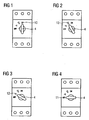
- the handle 4 receives a total of four positions 10, 11, 12 and 13 are provided. The four positions 10, 11, 12 and 13 represent the on state, the off state, the shutdown due to overload and the shutdown due to short circuit for the switching device, respectively.
- the first 12 and the second position 13 of the handle 4 are located between the third 10 and fourth position 11, wherein the angle of rotation of the handle 4 between the third position 10, in which the handle indicates the ON position of the device, and the fourth position 11, in which the handle 4 indicates the OFF position, is 90 °.
- Each position 10, 11, 12 and 13 is represented differently by an icon (or label) for easier recognition.
- the switching device When you turn the handle 4 to the ON position 10 ( FIG. 1 ), the switching device is switched on. If the handle 4, however, turned to the OFF position 11 ( FIG. 4 ), the switching device is switched off. In addition, the handle 4 can move automatically in position 12 or 13 and locked or locked there ( 3 and 2 ), if the switching device shuts off automatically due to overload or short circuit.
- the switching device When the switching device is switched off, for example due to overload, the handle 4 moves from the ON position 10 via the position 13, which indicates the triggering due to short circuit, in the position 12 and is locked in this position 12, to further rotation after to prevent the OFF position 11. This makes it possible, by the handle 4 in addition to the on and off state to be able to display the reasons for switching off the switching device recognizable without an additional component must be used.
- FIG. 5 shows the schematic structure of a switched-off switching device above.
- the switching device has a first trigger 2 for protection against overload and a second trigger 3 for protection against short circuit.
- the first trigger 2 is preferably a time-delayed thermo-bimetallic release
- the second trigger 3 is preferably an instantaneous electromagnetic release, which further comprises a coil 17 with an armature 16.
- the handle 4 has a toothed segment 6, and the switching mechanism 1 summarizes a mounted on a stationary axis switching gear 5 and at least one connecting lever 7 to.
- the handle 4 is mechanically coupled to the switching mechanism 1.
- the switching mechanism 1 is mechanically coupled to the triggers 2 and 3 respectively.
- a spring 15 is provided for exerting a force on the lever 9, so that the switching mechanism 1 can actuate the triggers 2 and 3 or the handle 4 by its mechanical movement, conversely the same applies.
- the handle 4 When the handle 4 is rotated to the position 11, the handle 4 engages by means of the toothed segment 6 in the shift gear 5 and rotates the shift gear 5. By the rotation of the shift gear 5, the switching mechanism 1, the switch contacts 14 open. As a result, the switching device is turned off, and at the same time, the handle 4 indicates the off state of the switching device in the OFF position 11.
- FIG. 6 A switched on same switching device is in FIG. 6 shown schematically.
- the handle 4 When the handle 4 is turned to the ON position 10, the handle 4 operates in the same manner the switch lock 1.
- the switch contacts 14 are closed to turn on the switching device again, while the handle 4 shows the on state of the switching device in the ON position 10 on.
- FIG. 7 the switching device has been switched off due to a short circuit.
- the lever 9 In normal operation, the lever 9 is mounted on the spring 15 and presses the spring 15 together. When short circuit, the armature 16 dips into the coil 17 of the trigger 3 and the lever 9 is thereby released. The lever 9 is pressed by the relaxed spring force against the handle 4 and locks the handle 4 in the position 13. At the same time the switch contacts 1, the switching contacts 14 open. Thus, the switching device is switched off and at the same time the handle 4 indicates the Abschaltground as a short circuit in the position 13.
- FIG. 8 the switching device has been switched off due to an overload.
- the bimetal of the trigger 2 heats up.
- the switching mechanism 1 is actuated via the lever 8.
- the coupled with him handle 4 is moved to position 12 and locked there.
- the switch contacts 14 are then opened.
- the switching device is switched off and indicates the handle 4 the Abschaltground as overload in the 12 position.
Landscapes
- Breakers (AREA)
- Emergency Protection Circuit Devices (AREA)
- Driving Mechanisms And Operating Circuits Of Arc-Extinguishing High-Tension Switches (AREA)
- Lock And Its Accessories (AREA)
Description
- Die Erfindung bezieht sich auf ein Schaltgerät mit einem Schaltschloss zur mechanischen Betätigung des Schaltgeräts, mit einem ersten Auslöser zum Schutz vor Überlast, mit einem zweiten Auslöser zum Schutz vor Kurzschluss und mit einer Handhabe zur Betätigung des Schaltschlosses bzw. ein Verfahren zur Anzeige der Abschaltursache eines derartigen Schaltgeräts.
- Zum Schutz von elektrischen Verbrauchern, z.B. Motoren, wird üblicherweise ein Schutzschalter verwendet, wobei er einen zeitlich verzögerten Auslöser zum Schutz vor Überlast und einen zeitlich unverzögerten Auslöser zum Schutz vor Kurzschluss besitzt. Dadurch, dass das Schaltschloss des Schutzschalters mit den Auslösern mechanisch gekoppelt wird, können die Auslöser durch automatisches Öffnen von Schaltkontakten den Stromkreis unterbrechen und das Abschalten des elektrischen Verbrauchers bewirken. Die Schaltkontakte können auch manuell mittels einer Handhabe des Schutzschalters geöffnet oder geschlossen werden, wobei die Handhabe mechanisch mit dem Schaltschloss gekoppelt oder im Schaltschloss integriert ist. Gleichzeitig sind der Ein-Zustand (eingeschalteter Schutzschalter) und der Aus-Zustand (ausgeschalteter Schutzschalter) durch die Stellung der Handhabe ersichtlich.
- Es ist bereits bekannt, dass ein Schutzschalter eine Handhabe, die außerhalb des Schaltergehäuses angeordnet ist, aufweist. Die Handhabe wird in eine Zwischenstellung, auch als Tripped-Stellung bekannt, zwischen Aus- und Einstellung gebracht, wenn der Schutzschalter durch einen Auslöser zum Schutz vor Überlast oder Kurzschluss abgeschaltet wird. Dabei wird nur die Abschaltung des Schutzschalters durch die Stellung der Handhabe angezeigt, es kann aber nicht zwischen Überlast und Kurzschluss unterschieden werden. Um die Ursache kenntlich zu machen, wird in einigen Geräten durch eine Lampe ein anhaubares Zusatzmodul oder durch eine integrierte zusätzliche Anzeige sichtbar angezeigt, welcher der Auslöser die Auslösung verursacht hat. Die Verwendung eines anbaubaren Zusatzmoduls oder einer integrierten zusätzlichen Anzeige ist einerseits bei den Herstellungskosten von Schutzschaltern ungünstig und andererseits wird die Vereinfachung der Struktur bzw. die Miniarisierung der Größe von Schutzschaltern erschwert.
-
US 2004/008098 A1 offenbart ein Schaltgerät gemäß Oberbegriff des Anspruchs 1, und ein Verfahren gemäß Oberbegriff des Anspruchs 8. - Der Erfindung liegt die Aufgabe zugrunde, die Abschaltursachen eines Schaltgeräts voneinander sichtlich zu unterscheiden.
- Die Aufgabe kann mit einem Schaltgerät nach Anspruch 1 und mit einem Verfahren nach Anspruch 8 gelöst werden. Die untergeordneten Ansprüche beschreiben weitere vorteilhafte Ausführungsformen der Erfindung.
- Der Erfindung liegt die Aufgabe zugrunde, in einem Schaltgerät durch die Stellung der Handhabe den Auslösegrund anzuzeigen. Wenn ein Schaltgerät, welches ein Schaltschloss zur mechanischen Betätigung des Schaltgeräts, einen ersten Auslöser zum Schutz vor Überlast, einen zweiten Auslöser zum Schutz vor Kurzschluss und eine Handhabe zur Betätigung des Schaltschlosses aufweist, um auf die Abschaltursache des Schaltgerätes hinzuweisen, dann wird das Schaltgerät derart ausgebildet, dass die Handhabe in eine erste Stellung bewegt wird, wenn der erste Auslöser wegen einer Überlast ausgelöst wird, und die Handhabe in eine zweite Stellung bewegt wird, wenn der zweite Auslöser wegen eines Kurzschlusses ausgelöst wird, wobei die erste und die zweite Stellung unterschiedlich sind. Dadurch kann bei einem abschalteten Schaltgerät der Auslösegrund auch ohne zusätzliche Anzeige auf eine einfache Weise kenntlich gemacht werden. Es wird auch kein zusätzlicher Platz auf der kleinen Sichtfläche auf dem Schaltgehäuse für weitere Anzeigeelemente benötigt.
- Gemäß einer vorteilhaften Ausgestaltung der Erfindung wird die Handhabe zur manuellen Betätigung des Schaltgeräts vorgesehen. Dabei wird die Handhabe zum Betätigen des Schaltschlosses derart ausgebildet, dass das Schaltgerät eingeschaltet wird, wenn die Handhabe in eine dritte Stellung bewegt wird, und dass das Schaltgerät ausgeschaltet wird, wenn die Handhabe in eine vierte Stellung bewegt wird. Alle vier Stellungen unterscheiden sich voneinander. Bei Verwendung des Schaltgeräts in einem Schaltschrank, in einem Gehäuse oder ähnlichem, werden durch die Stellung der Handhabe neben dem Ein- und Aus-Zustand auch die Abschaltgründe des Schaltgeräts außen auf der Schaltschranktür oder dem Gehäuse angezeigt.
- In einer vorteilhaften Ausführungsform wird das Schaltgerät derart ausgebildet, dass die Handhabe in die vier Stellungen durch eine Drehbewegung gelangt wird. Jede der vier Stellungen kann durch ein Symbol oder ein Zeichen dargestellt und bei einer drehbaren Handhabe bspw. in einem Kreis angeordnet werden. Durch Drehbewegung kann die Handhabe an jede Stellung erreichen und die Zustände und die Abschaltursachen des Schaltgeräts anzeigen.
- Vorteilhafterweise weist das Schaltgerät ein Schaltzahnrad auf, das ausgebildet ist, die Drehbewegung der Handhabe erzeugt. Durch das Schaltzahnrad kann die Drehbewegung der Handhabe auf das Schaltschloss übertragen werden, oder anders herum.
- Gemäß einer weiteren vorteilhaften Ausgestaltung der Erfindung wird das Schaltschloss derart ausgebildet, dass bei der Auslösung des ersten Auslösers die Handhabe in die erste Stellung bewegt und in der ersten Stellung gesperrt wird, und dass bei der Auslösung des zweiten Auslösers die Handhabe in die zweite Stellung bewegt und dort gesperrt wird. Die Handhabe kann auch in die dritte oder vierte Stellung bewegt und dort gesperrt werden, wenn das Schaltgerät ein- oder ausgeschaltet wird.
- In vorteilhafter Weise weist die Handhabe zumindest ein Zahnsegment auf, das mit dem Schaltzahnrad ausgebildet ist, um die Handhabe in einer der vier Stellungen zu sperren.
- In der Regel wird ein derartiges Schaltgerät als Leistungsschalter oder als Gerät, das einen Leistungsschalter aufweist, verwendet, um die Strombahnen zwischen einer elektrischen Versorgung und Verbrauchern zu schützen.
- Im Folgenden wird die Erfindung anhand der in den Figuren dargestellten Ausführungsbeispiele näher beschrieben und erläutert. Es zeigen:
- FIG 1
- eine Darstellung der Handhabe eines eingeschalten Schaltgerätes,
- FIG 2
- eine Darstellung der Handhabe eines ausgelösten Schaltgerätes wegen Kurzschluss,
- FIG 3
- eine Darstellung der Handhabe eines ausgelösten Schaltgerätes wegen Überlast,
- FIG 4
- eine Darstellung der Handhabe eines ausgeschalteten Schaltgerätes,
- FIG 5
- eine schematische Darstellung des Aus-Zustands des Schaltgerätes,
- FIG 6
- eine schematische Darstellung des Ein-Zustands des Schaltgerätes,
- FIG 7
- eine schematische Darstellung der Abschaltung des Schaltgerätes wegen Kurzschluss, und
- FIG 8
- eine schematische Darstellung der Abschaltung des Schaltgerätes wegen Überlast.
-
FIG 1 bis 4 zeigen jeweils eine Handhabe 4 eines Schaltgeräts, welches zum Schutz eines elektrischen Verbrauches, wie z.B. eines Motors, gegenüber Kurzschluss oder Überlast verwendet wird. Zudem kann das Schaltgerät durch Drehung der Handhabe 4 manuell aus- oder eingeschaltet werden. Um die Schaltzustände - ein- bzw. ausgeschaltet - sowie die Abschaltursache (Kurzschluss oder Überlast) des Schaltgeräts sichtlich anzuzeigen, werden bei der Handhabe 4 insgesamt vier Stellungen 10, 11, 12 und 13 vorgesehen. Die vier Stellungen 10, 11, 12 und 13 repräsentieren jeweils den Ein-Zustand, den Aus-Zustand, die Abschaltung wegen Überlast und die Abschaltung wegen Kurzschluss für das Schaltgerät. Die erste 12 und die zweite Stellung 13 der Handhabe 4 befinden sich zwischen der dritten 10 und vierten Stellung 11, wobei der Verdrehwinkel der Handhabe 4 zwischen der dritten Stellung 10, in der die Handhabe die EIN-Stellung des Gerätes anzeigt, und der vierten Stellung 11, in der die Handhabe 4 die AUS-Stellung anzeigt, 90° beträgt. Jede Stellung 10, 11, 12 und 13 wird durch ein Symbol (oder Beschriftung) zur leichteren Erkennung unterschiedlich dargestellt. - Wenn man die Handhabe 4 in die EIN-Stellung 10 dreht (
FIG 1 ), wird das Schaltgerät eingeschaltet. Wird die Handhabe 4 dagegen in die AUS-Stellung 11 gedreht (FIG 4 ), wird das Schaltgerät ausgeschaltet. Zudem kann sich die Handhabe 4 automatisch in Stellung 12 oder 13 bewegen und dort gesperrt oder verriegelt werden (FIG 3 und 2 ), wenn das Schaltgerät wegen Überlast oder wegen Kurzschluss automatisch abschaltet. Wenn das Schaltgerät z.B. wegen Überlast abgeschaltet wird, bewegt sich die Handhabe 4 von der EIN-Stellung 10 aus über die Stellung 13, welche die Auslösung wegen Kurzschluss anzeigt, in die Stellung 12 und wird in dieser Stellung 12 gesperrt, um eine weitere Drehung nach die AUS-Stellung 11 zu verhindern. Dadurch ist es möglich, alleine durch die Handhabe 4 neben dem Ein- und Aus-Zustand auch die Abschaltgründe des Schaltgeräts erkennbar anzeigen zu können, ohne dass ein zusätzliches Bauteil verwendet werden muss. -
FIG 5 zeigt den schematischen Aufbau eines ausgeschalteten oben genannten Schaltgerätes. Das Schaltgerät weist einen ersten Auslöser 2 zum Schutz vor Überlast und einen zweiten Auslöser 3 zum Schutz vor Kurzschluss auf. Der erste Auslöser 2 ist vorzugsweise ein zeitverzögerter Thermo-Bimetallauslöser, und der zweite Auslöser 3 ist vorzugsweise ein unverzögerter elektromagnetischer Auslöser, welcher ferner eine Spule 17 mit einem Anker 16 aufweist. Weiterhin weist das Schaltgerät ein Schaltschloss 1 zur mechanischen Betätigung beweglichen Kontakte 14 des Schaltgeräts und eine Handhabe 4 zum Betätigen des Schaltschlosses 1 auf. Die Handhabe 4 hat ein Zahnsegment 6, und das Schaltschloss 1 fasst ein um eine ortsfeste Achse gelagertes Schaltzahnrad 5 und mindestens einen Verbindungshebel 7 um. Dadurch, dass ein Zahnsegment 6 in das Schaltzahnrad 5 eingreift, wird die Handhabe 4 mit dem Schaltschloss 1 mechanisch gekoppelt. Über zwei Hebel 8 und 9 ist das Schaltschloss 1 jeweils mit den Auslösern 2 und 3 mechanisch gekoppelt. Eine Feder 15 ist zum Ausüben einer Kraft auf den Hebel 9 vorgesehen, damit das Schaltschloss 1 durch seine mechanische Bewegung die Auslöser 2 und 3 bzw. die Handhabe 4 betätigen kann, umgekehrt gilt das gleiche. - Wenn die Handhabe 4 in die Stellung 11 gedreht wird, greift die Handhabe 4 mittels des Zahnsegments 6 in das Schaltzahnrad 5 ein und dreht das Schaltzahnrad 5. Durch die Drehung des Schaltzahnrades 5 kann das Schaltschloss 1 die Schaltkontakte 14 öffnen. Dadurch wird das Schaltgerät ausgeschaltet, und gleichzeitig zeigt die Handhabe 4 den Aus-Zustand des Schaltgeräts in der AUS-Stellung 11 an.
- Ein eingeschaltetes gleiches Schaltgerät wird in
FIG 6 schematisch dargestellt. Wenn die Handhabe 4 in die EIN-Stellung 10 gedreht wird, betätigt die Handhabe 4 auf die gleiche Weise das Schaltschloss 1. Die Schaltkontakte 14 werden geschlossen, um das Schaltgerät wieder einzuschalten, währenddessen zeigt die Handhabe 4 den Ein-Zustand des Schaltgeräts in der EIN-Stellung 10 an. - In
FIG 7 ist das Schaltgerät wegen eines Kurzschlusses abgeschaltet worden. Im normalen Betrieb wird der Hebel 9 auf der Feder 15 gelagert und drückt die Feder 15 zusammen. Beim Kurzschluss taucht der Anker 16 in die Spule 17 des Auslösers 3 ein und der Hebel 9 wird dadurch freigegeben. Der Hebel 9 wird durch die entspannte Federkraft gegen die Handhabe 4 gedrückt und verriegelt die Handhabe 4 in der Stellung 13. Gleichzeitig werden über das Schaltschloss 1 die Schaltkontakte 14 geöffnet. Somit wird das Schaltgerät abgeschaltet und gleichzeitig zeigt die Handhabe 4 den Abschaltgrund als Kurzschluss in der Stellung 13 an. - In
FIG 8 ist das Schaltgerät wegen einer Überlast abgeschaltet worden. Bei Überlastung erwärmt sich das Bimetall des Auslösers 2. Durch die Ausbiegung des Bimetalls wird über den Hebel 8 das Schaltschloss 1 betätigt. Durch das Schaltschloss 1 wird die mit ihm gekoppelte Handhabe 4 in die Stellung 12 bewegt und dort verriegelt. Die Schaltkontakte 14 werden dann geöffnet. Somit wird das Schaltgerät abgeschaltet und zeigt die Handhabe 4 den Abschaltgrund als Überlastung in der Stellung 12 an.
Claims (13)
- Schaltgerät mit einem Schaltschloss (1) zur mechanischen Betätigung des Schaltgeräts, mit einem ersten Auslöser (2) zum Schutz vor Überlast, mit einem zweiten Auslöser (3) zum Schutz vor Kurzschluss, und mit einer Handhabe (4) zur Betätigung des Schaltschlosses (1),
dadurch gekennzeichnet, dass
das Schaltgerät ausgebildet ist, die Handhabe (4) in eine erste Stellung zu bewegen, wenn die Auslösung des ersten Auslösers (2) erfolgt, und
die Handhabe (4) in eine zweite Stellung (13) zu bewegen, wenn die Auslösung des zweiten Auslösers (3) erfolgt,
wobei die erste Stellung (12) und die zweite Stellung (13) unterschiedlich sind. - Schaltgerät nach Anspruch 1,
dadurch gekennzeichnet, dass
die Handhabe (4) zum Betätigen des Schaltschlosses (1) derart ausgebildet ist, dass das Schaltgerät eingeschaltet ist, wenn die Handhabe (4) in einer dritten Stellung (10) ist, und
dass das Schaltgerät ausgeschaltet ist, wenn die Handhabe (4) in einer vierten Stellung (11) bewegt wird,
wobei die vier Stellungen (10, 11, 12 und 13) sich voneinander unterscheiden. - Schaltgerät nach Anspruch 1 oder 2,
dadurch gekennzeichnet, dass
das Schaltgerät ausgebildet ist, die Handhabe (4) in die vier Stellungen (10, 11, 12 und 13) durch eine Drehbewegung zu stellen. - Schaltgerät nach Anspruch 3,
dadurch gekennzeichnet, dass
das Schaltgerät ein Schaltzahnrad (5) aufweist, das ausgebildet ist, die Drehbewegung der Handhabe (4) zu erzeugen. - Schaltgerät nach einem der vorherigen Ansprüche,
dadurch gekennzeichnet, dass
das Schaltschloss (1) ausgebildet ist, bei der Auslösung des ersten Auslösers (2) die Handhabe (4) in die erste Stellung (12) zu bewegen und in der ersten (12) Stellung zu sperren, bei der Auslösung des zweiten Auslösers (3) die Handhabe (4) in die zweite Stellung (13) zu bewegen und in der zweiten Stellung (13) zu sperren,
beim Einschalten des Schaltgeräts die Handhabe (4) in der dritten Stellung (10) zu sperren, und
beim Ausschalten des Schaltgeräts die Handhabe (4) in der vierten Stellung (11) zu sperren. - Schaltgerät nach einem der vorherigen Ansprüche,
dadurch gekennzeichnet, dass
die Handhabe (4) zumindest ein Zahnsegment (6) aufweist, das mit dem Schaltzahnrad (5) ausgebildet ist, die Handhabe (4) in einer der vier Stellungen (10, 11, 12 und 13) zu sperren. - Schaltgerät nach einem der Ansprüche 1 bis 6, wobei das Schaltgerät ein Leistungsschalter oder ein Gerät, das einen Leistungsschalter aufweist, ist.
- Verfahren zur Anzeige der Abschaltursache eines Schaltgeräts, wobei das Schaltgerät einen ersten Auslöser (2) zum Schutz vor Überlast, einen zweiten Auslöser (3) zum Schutz vor Kurzschluss, ein Schaltschloss (1) zur mechanischen Betätigung des Schaltgeräts, und eine Handhabe (4) zur Betätigung des Schaltschlosses (1) aufweist,
dadurch gekennzeichnet, dass
die Handhabe (4) in eine erste Stellung (12) bewegt wird, wenn die Auslösung des ersten Auslösers (2) erfolgt, und dass die Handhabe (4) in eine zweite Stellung (13) bewegt wird, wenn die Auslösung des zweiten Auslösers (3) erfolgt, und
wobei die erste Stellung (12) und die zweiten Stellung (13) unterschiedlich sind. - Verfahren nach Anspruch 8,
dadurch gekennzeichnet, dass
das Schaltgerät eingeschaltet wird, wenn die Handhabe (4) in eine dritte Stellung (10) bewegt wird, und
das Schaltgerät ausgeschaltet wird, wenn die Handhabe (4) in einer vierten Stellung (11) bewegt wird,
wobei die vier Stellungen (10, 11, 12, 13) sich voneinander unterscheiden. - Verfahren nach Anspruch 8 oder 9,
dadurch gekennzeichnet, dass
die Handhabe (4) in die vier Stellungen (10, 11, 12 und 13) durch eine Drehbewegung gestellt wird. - Verfahren nach Anspruch 10,
dadurch gekennzeichnet, dass
die Drehbewegung der Handhabe (4) durch ein Schaltzahnrad (5) erzeugt wird. - Verfahren nach einem der Ansprüche 8 bis 11,
dadurch gekennzeichnet, dass
bei der Auslösung des ersten Auslösers (2) die Handhabe (4) in die erste Stellung bewegt und in der ersten Stellung gesperrt wird,
bei der Auslösung des zweiten Auslösers (3) die Handhabe (4) in die zweite Stellung bewegt und in der zweiten Stellung gesperrt wird,
beim Einschalten des Schaltgeräts die Handhabe (4) in der dritten Stellung (10) gesperrt wird, und
beim Ausschalten des Schaltgeräts die Handhabe (4) in der vierten Stellung (11) gesperrt wird. - Verfahren nach Anspruch 12,
dadurch gekennzeichnet, dass
die Handhabe (4) dadurch gesperrt wird, dass die Handhabe (4) zumindest ein Zahnsegment (6) aufweist.
Priority Applications (6)
| Application Number | Priority Date | Filing Date | Title |
|---|---|---|---|
| DE502006003677T DE502006003677D1 (de) | 2006-09-29 | 2006-09-29 | Schaltgerät mit Schaltschloss |
| EP06020611A EP1906426B1 (de) | 2006-09-29 | 2006-09-29 | Schaltgerät mit Schaltschloss |
| AT06020611T ATE430985T1 (de) | 2006-09-29 | 2006-09-29 | Schaltgerät mit schaltschloss |
| CN2007101366693A CN101154538B (zh) | 2006-09-29 | 2007-07-18 | 具有开关锁扣的开关装置 |
| US11/900,340 US7583170B2 (en) | 2006-09-29 | 2007-09-11 | Switching device with switch latch |
| JP2007246526A JP4624390B2 (ja) | 2006-09-29 | 2007-09-25 | 開閉装置および開閉装置における遮断原因の表示方法 |
Applications Claiming Priority (1)
| Application Number | Priority Date | Filing Date | Title |
|---|---|---|---|
| EP06020611A EP1906426B1 (de) | 2006-09-29 | 2006-09-29 | Schaltgerät mit Schaltschloss |
Publications (2)
| Publication Number | Publication Date |
|---|---|
| EP1906426A1 EP1906426A1 (de) | 2008-04-02 |
| EP1906426B1 true EP1906426B1 (de) | 2009-05-06 |
Family
ID=37808306
Family Applications (1)
| Application Number | Title | Priority Date | Filing Date |
|---|---|---|---|
| EP06020611A Not-in-force EP1906426B1 (de) | 2006-09-29 | 2006-09-29 | Schaltgerät mit Schaltschloss |
Country Status (6)
| Country | Link |
|---|---|
| US (1) | US7583170B2 (de) |
| EP (1) | EP1906426B1 (de) |
| JP (1) | JP4624390B2 (de) |
| CN (1) | CN101154538B (de) |
| AT (1) | ATE430985T1 (de) |
| DE (1) | DE502006003677D1 (de) |
Families Citing this family (7)
| Publication number | Priority date | Publication date | Assignee | Title |
|---|---|---|---|---|
| DE102012008276A1 (de) * | 2011-07-25 | 2013-01-31 | Abb Technology Ag | Verriegelungsvorrichtung für eine Antriebseinheit eines Dreistellungsantriebes für ein Schaltgerät einer Schaltanlage |
| FR3023969B1 (fr) * | 2014-07-17 | 2017-12-22 | Schneider Electric Ind Sas | Dispositif de signalisation d'un defaut electrique dans un appareil de protection electrique, et appareil comportant un tel dispositif |
| CN104752111A (zh) * | 2015-03-04 | 2015-07-01 | 浙江天正电气股份有限公司 | 一种塑壳断路器 |
| KR200481214Y1 (ko) | 2015-06-24 | 2016-08-30 | 엘에스산전 주식회사 | 가스절연개폐장치의 조작기구 잠금장치 |
| CN106328402B (zh) * | 2015-06-30 | 2018-07-03 | 上海电科电器科技有限公司 | 电器开关的指示装置 |
| CN107658163B (zh) * | 2015-09-02 | 2019-02-15 | 涡阳县华夏气体有限公司 | 一种高压柜安全装置 |
| FR3051593B1 (fr) * | 2016-05-23 | 2019-10-04 | Schneider Electric Industries Sas | Dispositif de signalisation d'un defaut electrique dans un appareil de protection electrique, et appareil de protection electrique comportant un tel dispositif. |
Family Cites Families (9)
| Publication number | Priority date | Publication date | Assignee | Title |
|---|---|---|---|---|
| JPS631403Y2 (de) * | 1980-02-15 | 1988-01-14 | ||
| FR2538160B1 (fr) * | 1982-12-20 | 1985-12-13 | Telemecanique Electrique | Appareil contacteur a actionnement electromagnetique controle et a ouverture automatique lors de l'apparition de surcharges |
| US4598183A (en) * | 1984-07-27 | 1986-07-01 | Square D Company | Trip indicating circuit breaker operating handle |
| GB2246909B (en) * | 1990-07-16 | 1995-02-22 | Terasaki Denki Sangyo Kk | Circuit breaker including forced contact parting mechanism capable of self-retaining under short circuit condition |
| JP2517495B2 (ja) * | 1991-06-12 | 1996-07-24 | 寺崎電気産業株式会社 | 回路遮断器 |
| FR2799573B1 (fr) * | 1999-10-11 | 2001-12-14 | Schneider Electric Ind Sa | Mecanisme de commande de disjoncteur |
| JP3966058B2 (ja) * | 2002-04-19 | 2007-08-29 | 富士電機機器制御株式会社 | 回路しゃ断器 |
| CN1320579C (zh) * | 2005-07-06 | 2007-06-06 | 浙江中凯电器有限公司 | 一种控制与保护开关电器的操作机构 |
| CN1741224A (zh) * | 2005-07-27 | 2006-03-01 | 上海电器科学研究所(集团)有限公司 | 双推杆控制单一常开触头的故障区分操作机构 |
-
2006
- 2006-09-29 DE DE502006003677T patent/DE502006003677D1/de active Active
- 2006-09-29 EP EP06020611A patent/EP1906426B1/de not_active Not-in-force
- 2006-09-29 AT AT06020611T patent/ATE430985T1/de not_active IP Right Cessation
-
2007
- 2007-07-18 CN CN2007101366693A patent/CN101154538B/zh not_active Expired - Fee Related
- 2007-09-11 US US11/900,340 patent/US7583170B2/en not_active Expired - Fee Related
- 2007-09-25 JP JP2007246526A patent/JP4624390B2/ja not_active Expired - Fee Related
Also Published As
| Publication number | Publication date |
|---|---|
| US7583170B2 (en) | 2009-09-01 |
| CN101154538B (zh) | 2010-06-23 |
| JP2008091333A (ja) | 2008-04-17 |
| US20080079518A1 (en) | 2008-04-03 |
| DE502006003677D1 (de) | 2009-06-18 |
| JP4624390B2 (ja) | 2011-02-02 |
| EP1906426A1 (de) | 2008-04-02 |
| ATE430985T1 (de) | 2009-05-15 |
| CN101154538A (zh) | 2008-04-02 |
Similar Documents
| Publication | Publication Date | Title |
|---|---|---|
| EP0563774B1 (de) | Fernsteuerbarer Schutzschalter | |
| EP3131106B1 (de) | Verriegelungsvorrichtung für eine hochspannungsschaltanlage | |
| EP2137746B1 (de) | Verriegelungsvorrichtung für ein installationsschaltgerät | |
| DE102010036222B4 (de) | Anordnung mit einem elektrischen Schalter | |
| DE102009023347A1 (de) | Handbetätigter Schutzschalter mit austauschbarem Auslösemodul | |
| EP2436021B1 (de) | Schalteinheit für einen schutzschalter mit kipphebel | |
| EP1906426A1 (de) | Schaltgerät mit Schaltschloss | |
| DE102008016575B4 (de) | Voll-Schutzschalter und motorsteuerbarer Vollschutzschalter | |
| DE69008144T2 (de) | Selbstcoordinierendes schaltschutzgerät für elektrische apparate. | |
| DE102010019741B4 (de) | Schaltmechanik für einen Fehlerstromschutzschalter sowie Fehlerstromschutzschalter | |
| EP1671342B1 (de) | Schutzschalter | |
| DE102008011522A1 (de) | Baureihe von modular aufgebauten Schaltgeräten zur wahlweisen Verwendung in der Niederspannung oder Mittelspannung sowie Schaltschrank hierfür | |
| EP2059941B1 (de) | Hilfskontaktblock zur erweiterung eines schaltgerätes | |
| EP0820084B1 (de) | Betätigungsvorrichtung für Leistungsschaltgeräte | |
| EP0310943B1 (de) | Elektrisches Schaltgerät | |
| DE102011018498A1 (de) | Elektrisches Installationsgerät und System umfassend ein Installationsschaltgerät und einen Hilfsschalter | |
| DE102009020396B4 (de) | Fehlerstromschutzschalter | |
| DE202006015517U1 (de) | Mechanische Sicherheitsvorrichtung für Schaltgeräte | |
| DE3412325C2 (de) | ||
| EP2637270B1 (de) | Einschubrahmen für ein elektrisches Einschubschaltgerät, insbesondere ein Einschubleistungsschalter | |
| EP2533264B1 (de) | Hilfsschalter für einen elektrischen Schalter | |
| WO2025093210A1 (de) | Elektronisch schaltendes niederspannungs-schutzschaltgerät | |
| DE102012215482B3 (de) | Vorrichtung zum Betätigen eines elektrischen Schalters | |
| WO2025093212A1 (de) | Schaltmechanismus sowie elektronisch schaltendes niederspannungs-schutzschaltgerät | |
| WO2016096360A1 (de) | Drehbetätiger |
Legal Events
| Date | Code | Title | Description |
|---|---|---|---|
| PUAI | Public reference made under article 153(3) epc to a published international application that has entered the european phase |
Free format text: ORIGINAL CODE: 0009012 |
|
| AK | Designated contracting states |
Kind code of ref document: A1 Designated state(s): AT BE BG CH CY CZ DE DK EE ES FI FR GB GR HU IE IS IT LI LT LU LV MC NL PL PT RO SE SI SK TR |
|
| AX | Request for extension of the european patent |
Extension state: AL BA HR MK YU |
|
| 17P | Request for examination filed |
Effective date: 20080424 |
|
| GRAP | Despatch of communication of intention to grant a patent |
Free format text: ORIGINAL CODE: EPIDOSNIGR1 |
|
| AKX | Designation fees paid |
Designated state(s): AT BE BG CH CY CZ DE DK EE ES FI FR GB GR HU IE IS IT LI LT LU LV MC NL PL PT RO SE SI SK TR |
|
| GRAS | Grant fee paid |
Free format text: ORIGINAL CODE: EPIDOSNIGR3 |
|
| GRAA | (expected) grant |
Free format text: ORIGINAL CODE: 0009210 |
|
| AK | Designated contracting states |
Kind code of ref document: B1 Designated state(s): AT BE BG CH CY CZ DE DK EE ES FI FR GB GR HU IE IS IT LI LT LU LV MC NL PL PT RO SE SI SK TR |
|
| REG | Reference to a national code |
Ref country code: GB Ref legal event code: FG4D Free format text: NOT ENGLISH |
|
| REG | Reference to a national code |
Ref country code: CH Ref legal event code: EP |
|
| REG | Reference to a national code |
Ref country code: IE Ref legal event code: FG4D |
|
| REF | Corresponds to: |
Ref document number: 502006003677 Country of ref document: DE Date of ref document: 20090618 Kind code of ref document: P |
|
| PG25 | Lapsed in a contracting state [announced via postgrant information from national office to epo] |
Ref country code: ES Free format text: LAPSE BECAUSE OF FAILURE TO SUBMIT A TRANSLATION OF THE DESCRIPTION OR TO PAY THE FEE WITHIN THE PRESCRIBED TIME-LIMIT Effective date: 20090817 Ref country code: PT Free format text: LAPSE BECAUSE OF FAILURE TO SUBMIT A TRANSLATION OF THE DESCRIPTION OR TO PAY THE FEE WITHIN THE PRESCRIBED TIME-LIMIT Effective date: 20090906 Ref country code: LT Free format text: LAPSE BECAUSE OF FAILURE TO SUBMIT A TRANSLATION OF THE DESCRIPTION OR TO PAY THE FEE WITHIN THE PRESCRIBED TIME-LIMIT Effective date: 20090506 Ref country code: FI Free format text: LAPSE BECAUSE OF FAILURE TO SUBMIT A TRANSLATION OF THE DESCRIPTION OR TO PAY THE FEE WITHIN THE PRESCRIBED TIME-LIMIT Effective date: 20090506 |
|
| NLV1 | Nl: lapsed or annulled due to failure to fulfill the requirements of art. 29p and 29m of the patents act | ||
| PG25 | Lapsed in a contracting state [announced via postgrant information from national office to epo] |
Ref country code: IS Free format text: LAPSE BECAUSE OF FAILURE TO SUBMIT A TRANSLATION OF THE DESCRIPTION OR TO PAY THE FEE WITHIN THE PRESCRIBED TIME-LIMIT Effective date: 20090906 Ref country code: SE Free format text: LAPSE BECAUSE OF FAILURE TO SUBMIT A TRANSLATION OF THE DESCRIPTION OR TO PAY THE FEE WITHIN THE PRESCRIBED TIME-LIMIT Effective date: 20090806 Ref country code: PL Free format text: LAPSE BECAUSE OF FAILURE TO SUBMIT A TRANSLATION OF THE DESCRIPTION OR TO PAY THE FEE WITHIN THE PRESCRIBED TIME-LIMIT Effective date: 20090506 Ref country code: SI Free format text: LAPSE BECAUSE OF FAILURE TO SUBMIT A TRANSLATION OF THE DESCRIPTION OR TO PAY THE FEE WITHIN THE PRESCRIBED TIME-LIMIT Effective date: 20090506 Ref country code: LV Free format text: LAPSE BECAUSE OF FAILURE TO SUBMIT A TRANSLATION OF THE DESCRIPTION OR TO PAY THE FEE WITHIN THE PRESCRIBED TIME-LIMIT Effective date: 20090506 Ref country code: NL Free format text: LAPSE BECAUSE OF FAILURE TO SUBMIT A TRANSLATION OF THE DESCRIPTION OR TO PAY THE FEE WITHIN THE PRESCRIBED TIME-LIMIT Effective date: 20090506 |
|
| REG | Reference to a national code |
Ref country code: IE Ref legal event code: FD4D |
|
| PG25 | Lapsed in a contracting state [announced via postgrant information from national office to epo] |
Ref country code: CZ Free format text: LAPSE BECAUSE OF FAILURE TO SUBMIT A TRANSLATION OF THE DESCRIPTION OR TO PAY THE FEE WITHIN THE PRESCRIBED TIME-LIMIT Effective date: 20090506 Ref country code: RO Free format text: LAPSE BECAUSE OF FAILURE TO SUBMIT A TRANSLATION OF THE DESCRIPTION OR TO PAY THE FEE WITHIN THE PRESCRIBED TIME-LIMIT Effective date: 20090506 Ref country code: EE Free format text: LAPSE BECAUSE OF FAILURE TO SUBMIT A TRANSLATION OF THE DESCRIPTION OR TO PAY THE FEE WITHIN THE PRESCRIBED TIME-LIMIT Effective date: 20090506 Ref country code: IE Free format text: LAPSE BECAUSE OF FAILURE TO SUBMIT A TRANSLATION OF THE DESCRIPTION OR TO PAY THE FEE WITHIN THE PRESCRIBED TIME-LIMIT Effective date: 20090506 Ref country code: DK Free format text: LAPSE BECAUSE OF FAILURE TO SUBMIT A TRANSLATION OF THE DESCRIPTION OR TO PAY THE FEE WITHIN THE PRESCRIBED TIME-LIMIT Effective date: 20090506 |
|
| PG25 | Lapsed in a contracting state [announced via postgrant information from national office to epo] |
Ref country code: SK Free format text: LAPSE BECAUSE OF FAILURE TO SUBMIT A TRANSLATION OF THE DESCRIPTION OR TO PAY THE FEE WITHIN THE PRESCRIBED TIME-LIMIT Effective date: 20090506 |
|
| PLBE | No opposition filed within time limit |
Free format text: ORIGINAL CODE: 0009261 |
|
| STAA | Information on the status of an ep patent application or granted ep patent |
Free format text: STATUS: NO OPPOSITION FILED WITHIN TIME LIMIT |
|
| BERE | Be: lapsed |
Owner name: SIEMENS A.G. Effective date: 20090930 |
|
| PG25 | Lapsed in a contracting state [announced via postgrant information from national office to epo] |
Ref country code: BG Free format text: LAPSE BECAUSE OF FAILURE TO SUBMIT A TRANSLATION OF THE DESCRIPTION OR TO PAY THE FEE WITHIN THE PRESCRIBED TIME-LIMIT Effective date: 20090806 |
|
| 26N | No opposition filed |
Effective date: 20100209 |
|
| PG25 | Lapsed in a contracting state [announced via postgrant information from national office to epo] |
Ref country code: MC Free format text: LAPSE BECAUSE OF NON-PAYMENT OF DUE FEES Effective date: 20090930 |
|
| PG25 | Lapsed in a contracting state [announced via postgrant information from national office to epo] |
Ref country code: BE Free format text: LAPSE BECAUSE OF NON-PAYMENT OF DUE FEES Effective date: 20090930 |
|
| PG25 | Lapsed in a contracting state [announced via postgrant information from national office to epo] |
Ref country code: GR Free format text: LAPSE BECAUSE OF FAILURE TO SUBMIT A TRANSLATION OF THE DESCRIPTION OR TO PAY THE FEE WITHIN THE PRESCRIBED TIME-LIMIT Effective date: 20090807 |
|
| PG25 | Lapsed in a contracting state [announced via postgrant information from national office to epo] |
Ref country code: AT Free format text: LAPSE BECAUSE OF NON-PAYMENT OF DUE FEES Effective date: 20090929 |
|
| PG25 | Lapsed in a contracting state [announced via postgrant information from national office to epo] |
Ref country code: LU Free format text: LAPSE BECAUSE OF NON-PAYMENT OF DUE FEES Effective date: 20090929 |
|
| REG | Reference to a national code |
Ref country code: CH Ref legal event code: PL |
|
| GBPC | Gb: european patent ceased through non-payment of renewal fee |
Effective date: 20100929 |
|
| PG25 | Lapsed in a contracting state [announced via postgrant information from national office to epo] |
Ref country code: HU Free format text: LAPSE BECAUSE OF FAILURE TO SUBMIT A TRANSLATION OF THE DESCRIPTION OR TO PAY THE FEE WITHIN THE PRESCRIBED TIME-LIMIT Effective date: 20091107 |
|
| PG25 | Lapsed in a contracting state [announced via postgrant information from national office to epo] |
Ref country code: CH Free format text: LAPSE BECAUSE OF NON-PAYMENT OF DUE FEES Effective date: 20100930 Ref country code: LI Free format text: LAPSE BECAUSE OF NON-PAYMENT OF DUE FEES Effective date: 20100930 |
|
| PG25 | Lapsed in a contracting state [announced via postgrant information from national office to epo] |
Ref country code: TR Free format text: LAPSE BECAUSE OF FAILURE TO SUBMIT A TRANSLATION OF THE DESCRIPTION OR TO PAY THE FEE WITHIN THE PRESCRIBED TIME-LIMIT Effective date: 20090506 Ref country code: GB Free format text: LAPSE BECAUSE OF NON-PAYMENT OF DUE FEES Effective date: 20100929 |
|
| PG25 | Lapsed in a contracting state [announced via postgrant information from national office to epo] |
Ref country code: CY Free format text: LAPSE BECAUSE OF FAILURE TO SUBMIT A TRANSLATION OF THE DESCRIPTION OR TO PAY THE FEE WITHIN THE PRESCRIBED TIME-LIMIT Effective date: 20090506 |
|
| PGFP | Annual fee paid to national office [announced via postgrant information from national office to epo] |
Ref country code: DE Payment date: 20151120 Year of fee payment: 10 |
|
| REG | Reference to a national code |
Ref country code: FR Ref legal event code: PLFP Year of fee payment: 11 |
|
| PGFP | Annual fee paid to national office [announced via postgrant information from national office to epo] |
Ref country code: FR Payment date: 20160914 Year of fee payment: 11 |
|
| PGFP | Annual fee paid to national office [announced via postgrant information from national office to epo] |
Ref country code: IT Payment date: 20160928 Year of fee payment: 11 |
|
| REG | Reference to a national code |
Ref country code: DE Ref legal event code: R119 Ref document number: 502006003677 Country of ref document: DE |
|
| PG25 | Lapsed in a contracting state [announced via postgrant information from national office to epo] |
Ref country code: DE Free format text: LAPSE BECAUSE OF NON-PAYMENT OF DUE FEES Effective date: 20170401 |
|
| REG | Reference to a national code |
Ref country code: FR Ref legal event code: ST Effective date: 20180531 |
|
| PG25 | Lapsed in a contracting state [announced via postgrant information from national office to epo] |
Ref country code: FR Free format text: LAPSE BECAUSE OF NON-PAYMENT OF DUE FEES Effective date: 20171002 Ref country code: IT Free format text: LAPSE BECAUSE OF NON-PAYMENT OF DUE FEES Effective date: 20170929 |