EP1906447A2 - Kühlung der Leistungskomponenten eines Frequenzumrichters - Google Patents
Kühlung der Leistungskomponenten eines Frequenzumrichters Download PDFInfo
- Publication number
- EP1906447A2 EP1906447A2 EP07075813A EP07075813A EP1906447A2 EP 1906447 A2 EP1906447 A2 EP 1906447A2 EP 07075813 A EP07075813 A EP 07075813A EP 07075813 A EP07075813 A EP 07075813A EP 1906447 A2 EP1906447 A2 EP 1906447A2
- Authority
- EP
- European Patent Office
- Prior art keywords
- cooling
- condenser
- frame
- arrangement according
- piping
- Prior art date
- Legal status (The legal status is an assumption and is not a legal conclusion. Google has not performed a legal analysis and makes no representation as to the accuracy of the status listed.)
- Withdrawn
Links
Images

Classifications
-
- H—ELECTRICITY
- H10—SEMICONDUCTOR DEVICES; ELECTRIC SOLID-STATE DEVICES NOT OTHERWISE PROVIDED FOR
- H10W—GENERIC PACKAGES, INTERCONNECTIONS, CONNECTORS OR OTHER CONSTRUCTIONAL DETAILS OF DEVICES COVERED BY CLASS H10
- H10W40/00—Arrangements for thermal protection or thermal control
- H10W40/70—Fillings or auxiliary members in containers or in encapsulations for thermal protection or control
- H10W40/73—Fillings or auxiliary members in containers or in encapsulations for thermal protection or control for cooling by change of state
-
- H—ELECTRICITY
- H05—ELECTRIC TECHNIQUES NOT OTHERWISE PROVIDED FOR
- H05K—PRINTED CIRCUITS; CASINGS OR CONSTRUCTIONAL DETAILS OF ELECTRIC APPARATUS; MANUFACTURE OF ASSEMBLAGES OF ELECTRICAL COMPONENTS
- H05K7/00—Constructional details common to different types of electric apparatus
- H05K7/20—Modifications to facilitate cooling, ventilating, or heating
- H05K7/20218—Modifications to facilitate cooling, ventilating, or heating using a liquid coolant without phase change in electronic enclosures
-
- H—ELECTRICITY
- H05—ELECTRIC TECHNIQUES NOT OTHERWISE PROVIDED FOR
- H05K—PRINTED CIRCUITS; CASINGS OR CONSTRUCTIONAL DETAILS OF ELECTRIC APPARATUS; MANUFACTURE OF ASSEMBLAGES OF ELECTRICAL COMPONENTS
- H05K7/00—Constructional details common to different types of electric apparatus
- H05K7/20—Modifications to facilitate cooling, ventilating, or heating
- H05K7/2029—Modifications to facilitate cooling, ventilating, or heating using a liquid coolant with phase change in electronic enclosures
-
- H—ELECTRICITY
- H05—ELECTRIC TECHNIQUES NOT OTHERWISE PROVIDED FOR
- H05K—PRINTED CIRCUITS; CASINGS OR CONSTRUCTIONAL DETAILS OF ELECTRIC APPARATUS; MANUFACTURE OF ASSEMBLAGES OF ELECTRICAL COMPONENTS
- H05K7/00—Constructional details common to different types of electric apparatus
- H05K7/20—Modifications to facilitate cooling, ventilating, or heating
- H05K7/2089—Modifications to facilitate cooling, ventilating, or heating for power electronics, e.g. for inverters for controlling motor
- H05K7/20936—Liquid coolant with phase change
-
- H—ELECTRICITY
- H10—SEMICONDUCTOR DEVICES; ELECTRIC SOLID-STATE DEVICES NOT OTHERWISE PROVIDED FOR
- H10W—GENERIC PACKAGES, INTERCONNECTIONS, CONNECTORS OR OTHER CONSTRUCTIONAL DETAILS OF DEVICES COVERED BY CLASS H10
- H10W40/00—Arrangements for thermal protection or thermal control
- H10W40/40—Arrangements for thermal protection or thermal control involving heat exchange by flowing fluids
- H10W40/47—Arrangements for thermal protection or thermal control involving heat exchange by flowing fluids by flowing liquids, e.g. forced water cooling
Definitions
- the object of this invention is a power transformer, such as a frequency converter, a cooling arrangement for power components, in which is a cooler, which has a metal frame, to which the power components can be fitted, and cooling piping fitted inside the frame for removing thermal power from the power components by means of a flowing cooling medium, and a condenser connected to the cooling piping, with which thermal power can be transferred out of the cooling piping.
- a power transformer such as a frequency converter
- a cooling arrangement for power components in which is a cooler, which has a metal frame, to which the power components can be fitted, and cooling piping fitted inside the frame for removing thermal power from the power components by means of a flowing cooling medium, and a condenser connected to the cooling piping, with which thermal power can be transferred out of the cooling piping.
- semiconductor power components such as IGBTs
- a cooling plate which transfers thermal power further e.g. by means of cooling piping and the cooling liquid flowing in it onwards to a condenser, in which the thermal power can be transferred from the cooling liquid into the air.
- the purpose of this invention is to achieve a new kind of cooling arrangement for the power components of a frequency converter.
- the cooler and the condenser have a shared metal frame, in which one half functions as a cooler and the other half as a condenser, and inside which is fitted the shared cooling piping of the cooler and the condenser for the flowing cooling medium.
- the frame can be formed from one piece or otherwise from a plurality of frame pieces that are joined together.
- the cooling medium piping can contain channels provided with a turbulator (a turbulator is e.g. an additional part resembling a spiral spring, which achieves rotation of the liquid flow, i.e. turbulence, in the channel which has an advantageous effect on heat transfer) for arranging enclosed liquid circulation between the ends.
- the cooling medium can be a cooling liquid, which is circulated with a pump. It can also be water under low pressure, which boils in the cooling part and liquefies in the condenser part (heating pipe), and in which the liquid/vapour circulation between the parts occurs without a pump.
- An array of fins can be connected to the condenser part for transferring thermal power into the air duct e.g. forced by a fan.
- a separate liquid element can also be connected to the condenser part for transferring thermal power to an external liquid circulation.
- the frame of the cooling appliance can simultaneously function as the whole frame of the transformer appliance.
- a very compact and efficient cooling arrangement for the power components of a frequency converter can be achieved. More particularly by means of the invention point-like dissipation power dissipates utilizing all the cooling surface area, in which case cooling efficiency is significantly improved.
- Fig. 1 presents the transfer of dissipation power to a prior-art air cooler.
- Fig. 2 presents the transfer of dissipation power to an air cooler according to the invention.
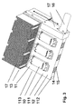
- Fig. 3 presents a perspective drawing of the cooling appliance of a frequency converter according to the invention.
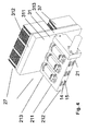
- Fig. 4 presents another cooling appliance of a frequency converter according to the invention.
- Fig. 1 presents how the dissipated power transfers to the cooler in a prior-art air cooler 1. Dissipated power is generated in the power semiconductor piece 3 contained in the power module 2, from where it transfers inside the cooler as is well known at a certain angle towards the cooling fins. Thus only a certain part of the array of fins of the cooler functions effectively (shaded part 4).
- Fig. 2 presents the principle of the cooling solution according to the invention.
- a pipe 4 containing liquid is disposed in the shared metal frame 1 under the power module, which pipe transfers the dissipated power of the power semiconductor piece 3 to the condenser part 5, of which the whole cooling surface area is utilized since the liquid pipe extends to the whole finned area.
- Fig. 3 presents a practical embodiment of a cooling appliance of a frequency converter according to the invention for cooling the power components 10 of the power stage, typically power semiconductor switches, e.g. IGBTs.
- the frame part of the cooling solution is an integral right-angled metal part 11, in which are face surfaces 111, of which semiconductor switches are situated on one, end surfaces 112, and side surfaces 113, and in which one half functions as a cooler 12, with which the transfer of thermal power from the power components to the liquid is achieved, and the other half as a condenser 13, by means of which the transfer of thermal power from the liquid into the air is achieved (so-called primary cooling), and inside which are parallel and longitudinal (see the arrow between the cooler part and the condenser part) channels 15, provided with a turbulator 14, for arranging enclosed cooling liquid circulation between the ends, in which case a liquid circulation is achieved inside the cooler.
- an expansion tank can be disposed e.g. at the end of the condenser.
- the liquid can be water, which is circulated with a pump 16, which contains a frame part 17, which is connected at its side surface to the side of the metal frame 11 of the appliance.
- the liquid can also be water under low pressure, which boils in the cooling part and liquefies by means of the heating pipes and the heating appliance in the condenser part, and in which the liquid/vapour circulation between the parts occurs without a pump.
- the liquid/vapour circulation can also be implemented in another manner suited to the purpose.
- a metallic array of fins 17 is joined to one of the face surfaces or to both face surfaces (top and bottom surfaces) of the condenser part 13 for transferring dissipated power to the air duct under the force of the fan.
- a separate liquid element can be connected to the condenser part for transferring thermal power to an external liquid circulation.
- Fig. 4 presents another embodiment of a cooling appliance according to the invention, which has two right-angled frame parts 21 and 31, on which are face surfaces 211, 311, end surfaces 212, 312 and side surfaces 213, 313, and in which the frame parts are joined tightly together at the end surface 212 of one part and at the face surface 311 of the other part, and in both of which frame parts is cooling piping on the inside such that when joined together they form an integral cooling piping.
- IGBTs are arranged on the face surface of one frame part, which functions as a cooler, and a cooling array of fins to the other face surface of the other frame part, which can be comprised of two different fin array parts 27, 37, and which thus functions as a condenser.
Landscapes
- Engineering & Computer Science (AREA)
- Microelectronics & Electronic Packaging (AREA)
- Physics & Mathematics (AREA)
- Thermal Sciences (AREA)
- Cooling Or The Like Of Electrical Apparatus (AREA)
- Transformer Cooling (AREA)
Applications Claiming Priority (1)
| Application Number | Priority Date | Filing Date | Title |
|---|---|---|---|
| FI20060868A FI122741B (fi) | 2006-09-29 | 2006-09-29 | Tehomuuttajan tehokomponenttien jäähdytys |
Publications (2)
| Publication Number | Publication Date |
|---|---|
| EP1906447A2 true EP1906447A2 (de) | 2008-04-02 |
| EP1906447A3 EP1906447A3 (de) | 2010-04-14 |
Family
ID=37067190
Family Applications (1)
| Application Number | Title | Priority Date | Filing Date |
|---|---|---|---|
| EP07075813A Withdrawn EP1906447A3 (de) | 2006-09-29 | 2007-09-18 | Kühlung der Leistungskomponenten eines Frequenzumrichters |
Country Status (3)
| Country | Link |
|---|---|
| US (1) | US20080078529A1 (de) |
| EP (1) | EP1906447A3 (de) |
| FI (1) | FI122741B (de) |
Cited By (2)
| Publication number | Priority date | Publication date | Assignee | Title |
|---|---|---|---|---|
| FR3010274A1 (fr) * | 2013-08-27 | 2015-03-06 | Valeo Equip Electr Moteur | Bloc convertisseur de puissance de vehicule electrique ou hybride |
| CN111552327A (zh) * | 2020-05-15 | 2020-08-18 | 上海蔚星科技有限公司 | 基于相变材料及金属微膨胀的航天器用双驱空间热开关 |
Families Citing this family (5)
| Publication number | Priority date | Publication date | Assignee | Title |
|---|---|---|---|---|
| FI20126218A7 (fi) * | 2012-11-20 | 2014-05-21 | Vacon Oy | Tehoelektroniikkalaite |
| DE102013203114A1 (de) * | 2013-02-26 | 2014-09-11 | Siemens Aktiengesellschaft | Umrichterkühlung mit Phasenwechselspeicher |
| CN107949234A (zh) * | 2016-10-10 | 2018-04-20 | 南京南瑞集团公司 | 一种用于柔性直流输电换流阀的冷却系统 |
| JP6595531B2 (ja) * | 2017-05-30 | 2019-10-23 | ファナック株式会社 | ヒートシンクアッセンブリ |
| CN114554051B (zh) * | 2022-02-11 | 2024-03-08 | 杭州海康威视数字技术股份有限公司 | 摄像模组及其控制方法 |
Citations (2)
| Publication number | Priority date | Publication date | Assignee | Title |
|---|---|---|---|---|
| JPH09107058A (ja) | 1995-10-12 | 1997-04-22 | Denso Corp | 沸騰冷却装置 |
| JP2005229102A (ja) | 2004-01-13 | 2005-08-25 | Fuji Electric Systems Co Ltd | ヒートシンク |
Family Cites Families (15)
| Publication number | Priority date | Publication date | Assignee | Title |
|---|---|---|---|---|
| JPS5512740B2 (de) * | 1974-03-15 | 1980-04-03 | ||
| JPS54116178A (en) * | 1978-03-01 | 1979-09-10 | Sony Corp | Protective unit for semiconductor element |
| US4706355A (en) * | 1984-12-11 | 1987-11-17 | Q-Dot Corporation | Method of making an internally grooved and expanded tubular heat exchanger apparatus |
| EP0401743B1 (de) * | 1989-06-08 | 1998-01-07 | The Furukawa Electric Co., Ltd. | Kühlvorrichtung mit elektrisch isoliertem Wärmerohr für Halbleiter |
| US5316077A (en) * | 1992-12-09 | 1994-05-31 | Eaton Corporation | Heat sink for electrical circuit components |
| US5453641A (en) * | 1992-12-16 | 1995-09-26 | Sdl, Inc. | Waste heat removal system |
| JP3810119B2 (ja) * | 1996-03-07 | 2006-08-16 | 株式会社デンソー | 沸騰冷却装置 |
| US6019165A (en) * | 1998-05-18 | 2000-02-01 | Batchelder; John Samuel | Heat exchange apparatus |
| CA2425111C (en) * | 2000-11-03 | 2010-06-01 | Smc Electrical Products, Inc. | Microdrive |
| US6437981B1 (en) * | 2000-11-30 | 2002-08-20 | Harris Corporation | Thermally enhanced microcircuit package and method of forming same |
| FI117838B (fi) * | 2003-06-04 | 2007-03-15 | Vacon Oyj | Nestejäähdytyselementti ja nestejäähdytyselementin liittämisjärjestely |
| FI118781B (fi) * | 2003-06-04 | 2008-03-14 | Vacon Oyj | Kondensaattorin kiinnitys- ja suojajärjestely |
| US7055581B1 (en) * | 2003-06-24 | 2006-06-06 | Roy Sanjay K | Impeller driven active heat sink |
| JP2005195226A (ja) * | 2004-01-06 | 2005-07-21 | Mitsubishi Electric Corp | ポンプレス水冷システム |
| JP4305406B2 (ja) * | 2005-03-18 | 2009-07-29 | 三菱電機株式会社 | 冷却構造体 |
-
2006
- 2006-09-29 FI FI20060868A patent/FI122741B/fi not_active IP Right Cessation
-
2007
- 2007-09-18 EP EP07075813A patent/EP1906447A3/de not_active Withdrawn
- 2007-09-27 US US11/905,096 patent/US20080078529A1/en not_active Abandoned
Patent Citations (2)
| Publication number | Priority date | Publication date | Assignee | Title |
|---|---|---|---|---|
| JPH09107058A (ja) | 1995-10-12 | 1997-04-22 | Denso Corp | 沸騰冷却装置 |
| JP2005229102A (ja) | 2004-01-13 | 2005-08-25 | Fuji Electric Systems Co Ltd | ヒートシンク |
Cited By (3)
| Publication number | Priority date | Publication date | Assignee | Title |
|---|---|---|---|---|
| FR3010274A1 (fr) * | 2013-08-27 | 2015-03-06 | Valeo Equip Electr Moteur | Bloc convertisseur de puissance de vehicule electrique ou hybride |
| EP2844052A3 (de) * | 2013-08-27 | 2015-08-05 | Valeo Equipements Electriques Moteur | Leistungswandlerblock für Elektro- oder Hybridfahrzeug |
| CN111552327A (zh) * | 2020-05-15 | 2020-08-18 | 上海蔚星科技有限公司 | 基于相变材料及金属微膨胀的航天器用双驱空间热开关 |
Also Published As
| Publication number | Publication date |
|---|---|
| FI20060868A0 (fi) | 2006-09-29 |
| FI20060868L (fi) | 2008-03-30 |
| FI122741B (fi) | 2012-06-15 |
| US20080078529A1 (en) | 2008-04-03 |
| EP1906447A3 (de) | 2010-04-14 |
Similar Documents
| Publication | Publication Date | Title |
|---|---|---|
| US7604040B2 (en) | Integrated liquid cooled heat sink for electronic components | |
| US6714413B1 (en) | Compact thermosiphon with enhanced condenser for electronics cooling | |
| US6834713B2 (en) | Thermosiphon for electronics cooling with nonuniform airflow | |
| US7204299B2 (en) | Cooling assembly with sucessively contracting and expanding coolant flow | |
| CN212991086U (zh) | 散热器 | |
| US7077189B1 (en) | Liquid cooled thermosiphon with flexible coolant tubes | |
| US7506682B2 (en) | Liquid cooled thermosiphon for electronic components | |
| EP1906447A2 (de) | Kühlung der Leistungskomponenten eines Frequenzumrichters | |
| CN201044554Y (zh) | 水冷式微槽群与热电组合激光器热控制系统 | |
| JP5323614B2 (ja) | ヒートパイプおよびその製造方法 | |
| CN106488687B (zh) | 用于对封闭的机柜进行冷却的装置 | |
| WO2017148197A1 (zh) | 散热设备 | |
| TW200537068A (en) | Multiple evaporator heat pipe assisted heat sink | |
| KR20080041980A (ko) | 컴퓨터 모듈 | |
| US20180286844A1 (en) | Cooling system for high power application specific integrated circuit with embedded high bandwidth memory | |
| CN111664733B (zh) | 一种微通道换热器结合热管的散热装置 | |
| US20120217630A1 (en) | Heatsink, heatsink assembly, semiconductor module, and semiconductor device with cooling device | |
| US10989453B2 (en) | Heat exchanger with improved heat removing efficiency | |
| CN100468707C (zh) | 循环热管散热器 | |
| US10907910B2 (en) | Vapor-liquid phase fluid heat transfer module | |
| CN201044553Y (zh) | 风冷式微槽群与热电组合激光器热控制系统 | |
| CN111010847B (zh) | 一种均热板式散热装置 | |
| CN101004627A (zh) | 散热器 | |
| CN108106473B (zh) | 汽液相流热传模块 | |
| CN104582419A (zh) | 一种用于通讯机柜的换热器 |
Legal Events
| Date | Code | Title | Description |
|---|---|---|---|
| PUAI | Public reference made under article 153(3) epc to a published international application that has entered the european phase |
Free format text: ORIGINAL CODE: 0009012 |
|
| AK | Designated contracting states |
Kind code of ref document: A2 Designated state(s): AT BE BG CH CY CZ DE DK EE ES FI FR GB GR HU IE IS IT LI LT LU LV MC MT NL PL PT RO SE SI SK TR |
|
| AX | Request for extension of the european patent |
Extension state: AL BA HR MK YU |
|
| PUAL | Search report despatched |
Free format text: ORIGINAL CODE: 0009013 |
|
| AK | Designated contracting states |
Kind code of ref document: A3 Designated state(s): AT BE BG CH CY CZ DE DK EE ES FI FR GB GR HU IE IS IT LI LT LU LV MC MT NL PL PT RO SE SI SK TR |
|
| AX | Request for extension of the european patent |
Extension state: AL BA HR MK RS |
|
| 17P | Request for examination filed |
Effective date: 20100915 |
|
| 17Q | First examination report despatched |
Effective date: 20101108 |
|
| AKX | Designation fees paid |
Designated state(s): AT BE BG CH CY CZ DE DK EE ES FI FR GB GR HU IE IS IT LI LT LU LV MC MT NL PL PT RO SE SI SK TR |
|
| RAP1 | Party data changed (applicant data changed or rights of an application transferred) |
Owner name: VACON OY |
|
| STAA | Information on the status of an ep patent application or granted ep patent |
Free format text: STATUS: THE APPLICATION IS DEEMED TO BE WITHDRAWN |
|
| 18D | Application deemed to be withdrawn |
Effective date: 20160301 |