EP1906690A1 - Appareil d'antenne, réseau cellulaire sans fil et procédé pour accroître la capacité de réseau cellulaire sans fil - Google Patents
Appareil d'antenne, réseau cellulaire sans fil et procédé pour accroître la capacité de réseau cellulaire sans fil Download PDFInfo
- Publication number
- EP1906690A1 EP1906690A1 EP07720885A EP07720885A EP1906690A1 EP 1906690 A1 EP1906690 A1 EP 1906690A1 EP 07720885 A EP07720885 A EP 07720885A EP 07720885 A EP07720885 A EP 07720885A EP 1906690 A1 EP1906690 A1 EP 1906690A1
- Authority
- EP
- European Patent Office
- Prior art keywords
- signals
- layer
- phase
- channels
- output
- Prior art date
- Legal status (The legal status is an assumption and is not a legal conclusion. Google has not performed a legal analysis and makes no representation as to the accuracy of the status listed.)
- Granted
Links
Images


Classifications
-
- H—ELECTRICITY
- H01—ELECTRIC ELEMENTS
- H01Q—ANTENNAS, i.e. RADIO AERIALS
- H01Q3/00—Arrangements for changing or varying the orientation or the shape of the directional pattern of the waves radiated from an antenna or antenna system
- H01Q3/26—Arrangements for changing or varying the orientation or the shape of the directional pattern of the waves radiated from an antenna or antenna system varying the relative phase or relative amplitude of energisation between two or more active radiating elements; varying the distribution of energy across a radiating aperture
- H01Q3/30—Arrangements for changing or varying the orientation or the shape of the directional pattern of the waves radiated from an antenna or antenna system varying the relative phase or relative amplitude of energisation between two or more active radiating elements; varying the distribution of energy across a radiating aperture varying the relative phase between the radiating elements of an array
- H01Q3/34—Arrangements for changing or varying the orientation or the shape of the directional pattern of the waves radiated from an antenna or antenna system varying the relative phase or relative amplitude of energisation between two or more active radiating elements; varying the distribution of energy across a radiating aperture varying the relative phase between the radiating elements of an array by electrical means
- H01Q3/40—Arrangements for changing or varying the orientation or the shape of the directional pattern of the waves radiated from an antenna or antenna system varying the relative phase or relative amplitude of energisation between two or more active radiating elements; varying the distribution of energy across a radiating aperture varying the relative phase between the radiating elements of an array by electrical means with phasing matrix
-
- H—ELECTRICITY
- H01—ELECTRIC ELEMENTS
- H01Q—ANTENNAS, i.e. RADIO AERIALS
- H01Q1/00—Details of, or arrangements associated with, antennas
- H01Q1/12—Supports; Mounting means
- H01Q1/22—Supports; Mounting means by structural association with other equipment or articles
- H01Q1/24—Supports; Mounting means by structural association with other equipment or articles with receiving set
- H01Q1/241—Supports; Mounting means by structural association with other equipment or articles with receiving set used in mobile communications, e.g. GSM
- H01Q1/246—Supports; Mounting means by structural association with other equipment or articles with receiving set used in mobile communications, e.g. GSM specially adapted for base stations
-
- H—ELECTRICITY
- H01—ELECTRIC ELEMENTS
- H01Q—ANTENNAS, i.e. RADIO AERIALS
- H01Q25/00—Antennas or antenna systems providing at least two radiating patterns
-
- H—ELECTRICITY
- H04—ELECTRIC COMMUNICATION TECHNIQUE
- H04W—WIRELESS COMMUNICATION NETWORKS
- H04W16/00—Network planning, e.g. coverage or traffic planning tools; Network deployment, e.g. resource partitioning or cells structures
Definitions
- the present invention relates to mobile communication technologies and in particular to an antenna device, a wireless cellular network and a method for expanding capacity of a wireless cellular network.
- a service area is covered by a plurality of Base Stations (BTS).
- An existing antenna of a base station has a single column of antennas, where there is only a longitudinal feed network but no horizontal feed network with a directivity diagram of approximately a regular hexagon.
- the coverage area of a base station adopting such antennas is like a cell of a beehive, and thus an existing mobile communication system is called as a "Cellular System".
- a mobile communication system may have numerous cells, and investment for that is very high, usually as high as tens or even hundreds of billions. Hence, if each base station covers a larger area, i.e.
- the area of a cell is larger, the total number of base stations will be reduced, and thus the investment cost will be lowered.
- the capacity of each base station is limited, so its capacity density will be decreased with an enlarged coverage area.
- New base stations may need to be established with the number of users increasing, which is called network capacity expansion. With new base stations established, the area covered by an old cell should be diminished so as to make space for the newly-established base stations. This is called network splitting.
- An ideal networking approach is to have larger coverage areas for individual base stations when initially establishing a network so as to reduce initial investment (because the number of registered users increases regularly from zero), and thus diminish capital to be invested and risk of investment, and to expand the capacity step by step with the number of users increasing, i.e. to split the network step by step.
- capacity expansion by means of network splitting requires additional necessary equipment, results in extra costs, and requires complex reconfiguration of local networks. Consequently, the network capacity expansion is neither "smooth" nor cost effective. Accordingly, the low initial investment conflicts with the high capacity expansion cost.
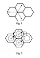
- FIG. 1 is a schematic diagram of three-sector coverage, in which the circle indicates a location of a base station, and the arrows indicate directivities of an antenna of the base station. In such a structure, directivities of antennas are staggered. This is a favorable networking approach, and thus has been widely applied.
- the topology after capacity expansion should be as illustrated in Figure 2 .
- coverage areas will be changed, and existing antennas shall be replaced with antennas of new specifications directivities and tilt angles of which must be reconfigured depending on antennas of the newly established base station.
- the coverage areas are not normative, it may be difficult to obtain a good coverage for some dead zones regardless of adjusting. Therefore, to maintain a three-sector network structure, both locations and coverage areas of original base stations shall be changed, which will pose a great impact upon the original network.
- a existing "one-off" network planning principle is commonly employed to avoid the above unsmooth capacity expansion, i.e. a network is planned and established considering capacity demand in future several years.
- This planning approach ensures that the network capacity will be sufficient in the coming several years, and therefore no capacity expansion will be needed.
- An advantage of this approach is that it satisfies a requirement for the number base stations in the coming years, while its disadvantage is that the initial investment will be large, which may bring an investment challenge to an operator.
- the total number of base stations fails to be reduced, and the total cost of base station sites can not be lowered.
- each base station involves some fixed costs such as cost of site building, accumulators, and tenancy. The more the base station sites, the higher the costs. Because the "one-off" planning requires more base stations, the costs of base station sites are higher.
- Embodiments of the present invention provide an antenna device, a wireless cellular network, and a method of capacity expansion, which can enable a simple and efficient capacity expansion for a communication network.
- An antenna device includes:
- a wireless cellular network includes:
- a method of capacity expansion for a wireless cellular network includes receiving original signals from a base station; allocating the original signals with preset amplitudes and phases; and transmitting the signals allocated with the amplitudes and phases through an array of antennas comprising an even number of columns so as to expand a network capacity to a preset multiple.
- An array of antennas including an even number of columns has been adopted in the embodiments of the present invention, and the feed network structure of the antenna system has been improved.
- By adjusting the amplitudes and phases of original signals from a base station it is possible to divide a regular-hexagon sector covered by an antenna of an existing base station into two semi-regular-hexagon sectors, or to divide a sector covered by an antenna of an existing base station into a plurality of sectors according to a preset multiple.
- no additional base station sites are increased, and no antenna directivities need to be adjusted, thus a smooth capacity expansion may be achieved, the workload and complexity for capacity expansion may be reduced.
- coverage area of a base station can be increased during network planning, thus the number of base stations may be reduced, and the coverage cost may be lowered.
- Figure 1 is a schematic diagram of coverage areas of a base station in the prior art
- Figure 2 is a schematic diagram of coverage areas of a base station after capacity expansion in the prior art
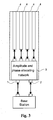
- FIG. 3 is a structural diagram of an antenna device according to an embodiment of the present invention.
- Figure 4 is a structural diagram of an amplitude and phase allocating network according to an embodiment of the present invention.
- Figure 5 is a structural diagram of an amplitude and phase allocating network according to another embodiment of the present invention.
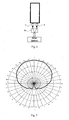
- Figure 6 is a schematic diagram of an antenna being connected to a base station through a power divider according to an embodiment of the present invention
- Figure 7 is a directivity diagram of an antenna when connected to a base station through a power divider according to an embodiment of the present invention
- Figure 8 is a schematic diagram of an antenna being connected directly to a base station according to an embodiment of the present invention.
- Figure 9 is a directivity diagram of an antenna when connected directly to a base station according to an embodiment of the present invention.
- FIG 3 is a structural diagram of an antenna device according to a first embodiment of the present invention.
- the antenna device is connected with a base station through a left contact 1 and a right contact 2.
- the device further includes an amplitude and phase allocating network 3 for allocating signals from the base station to an array of antennas with designed amplitudes and phases, and a splitting antenna 4 with an array of antennas comprising four columns for transmitting and receiving signals.
- Signals output from the left contact 1 or the right contact 2 pass the amplitude and phase allocating network 3 to generate four outputs respectively linked with the antennas of the array 4.
- the amplitude and phase allocating network 3 includes:
- two layer-2 3-decibel 90-degree bridges 81 and 82 each of which halves signals from one of two input channels to two channels and outputs, signals from the two output channels have a phase difference of 90 degrees;
- Signals inputted through the left contact 1 or the right contact 2 pass the amplitude and phase allocating network 3, and then four outputs with relative amplitudes of 0.4/1/1/0.4 and phases incrementing or decrementing by 90 degrees are generated, wherein a certain error is tolerated with respect to the amplitudes and the phases.
- the amplitude and phase allocating network may have a symmetric network structure and a good property of stationary waves.
- the antenna device can also be implemented by a plurality of paratactic antennas.
- a united coverage area of a respective sub-sector formed by the paratactic antennas can be in correspondence with a coverage area of a corresponding sector before splitting.
- corresponding carriers can be set in the sub-sectors formed after splitting, so as to achieve network capacity expansion without changing a coverage area of a base station.
- the antenna directivity diagram formed by the two paratactic antennas is eudipleural, i.e. each sector of the base station is split into two corresponding eudipleural sub-sectors. In this case, the network capacity is theoretically doubled.
- two paratactic antennas are used for capacity expansion of a three-sector network. Because the three-sector structure of the wireless cellular network is not changed, directivities and tilt-down angles of the antennas shall not be adjusted for installation, thus resulting in a convenient network capacity expansion.
- the antenna structure may be identical to that in the first embodiment and a structure of the amplitude and phase allocating network 3 is illustrated in Figure 5 .
- the amplitude and phase allocating network 3 includes:
- two 3-decibel 90-degree bridges 131 and 132 each of which halves signals from one of two input channels to two channels and outputs, signals from the two output channels have a difference of 90 degrees, and are output through an array of antennas including four columns.
- amplitude and phase allocating network in this embodiment are identical to those of the corresponding part in the first embodiment except that the amplitude and phase allocating network in this embodiment is of only two levels, and thus has an advantage of lower loss in comparison with the first embodiment.
- an antenna device of a base station is connected to the base station through a power divider 14 during initial networking.
- a function of the power divider 14 here is to divide power of signals from a channel of the base station into two channels.
- the signals are halved into two channels and linked respectively to two input contacts of an antenna, allocated with amplitudes and phases, and then are transmitted through the array of antennas comprising multiple columns.
- the allocation of amplitudes and phases by the amplitude and phase allocating network particularly includes the following steps:
- base station signals from the left contact 1 pass the layer-1 3-dechbile 90-degree bridge 51, and are power-halved to generate two outputs, one of which lags the other by a phase of 90 degrees;
- one of the outputs of the layer-1 3-dechbile 90-degree bridge 51 passes a 90-degree phase shifter 71, and is phase delayed by 90 degrees, then enters the layer-2 3-decibel 90-degree bridge 82, where it is power-halved to generate two layer-2 outputs, one of which lags the other by a phase of 90 degrees; the other output of the layer-1 3-dechbile 90-degree bridge 51 enters the layer-2 3-decibel 90-degree bridge 81, and is power-halved to generate other two layer-2 outputs, one of which lags the other by a phase of 90 degrees;
- one of the two layer-2 outputs passes the 45-degree phase shifter 92 and is phase delayed by 45 degrees, then enters the layer-3 3-decibel 90-degree bridge 102 where it is power-halved to generate two layer-3 outputs, one of which lags the other by a phase of 90 degrees, the one of the two layer-3 outputs enters an antenna array b, and the other of the two layer-3 outputs enters an antenna array d; other of the two layer-2 outputs enters the layer-3 3-decibel 90-degree bridge 101, and is power-halved to generate two layer-3 outputs, one of which lags the other by a phase of 90 degrees, the one of the two layer-3 outputs enters an antenna array a, the other of the two layer-3 outputs enters an antenna array c; one of the other two layer-2 outputs enters the layer-3 3-decibel 90-degree bridge 102, and is power-halved to generate two layer-3 outputs, one of which lags the other by a phase of 90 degrees, one of the two
- the allocation of amplitudes and phases by the amplitude and phase allocating network particularly includes the following steps:
- base station signals from the left contact 1 enter the 7.7-decibel coupler 111, power of one output of the coupler is lower than that of the another output of the coupler by 7.7 decibels; one of the outputs of the 7.7-decibel coupler 111 enters the 3-decibel 90-degree bridge 131 and is powered-halved to generate two outputs, one of which lags the other by a phase of 90 degrees, the one of the two outputs enters an antenna array a, and the other of the outputs enters an antenna array d; the other of the outputs of the 7.7-decibel coupler 111 passes the 180-degree phase shifter 121 and is phase delayed by 180 degrees, then enters the 3-decibel 90-degree bridge 132, where it is power-halved to generate two outputs, one of which lags the other by a phase of 90 degrees, the one of the two outputs enters an antenna array c, and the other of the two outputs enters an antenna array b;
- base station signals from the right contact 2 enter the 7.7-decibel coupler 112, power of one output of the coupler is lower than that of the another output of the coupler by 7.7 decibels; one of the outputs of the 7.7-decibel coupler 112 enters the 3-decibel 90-degree bridge 131 and is power-halved to generate two outputs, one of which lags the other by a phase of 90 degrees, one of the two outputs enters the antenna array d, and the other of the two outputs enters the antenna array a; and the other of the outputs of the 7.7-decibel coupler 112 passes the 180-degree phase shifter 122 and is phase delayed by 180 degrees, then enters the 3-decibel 90-degree bridge 132, and is power-halved to generate two outputs, one of which lags the other by a phase of 90 degrees, the one of the two outputs enters the antenna array b, and the other of the two outputs enters the antenna array c.
- the number of terminals supported in the coverage area of the antennas is the number of terminals supported by signals from one channel.
- Base station signals from one channel enter a contact of the antennas and are allocated with phases and amplitudes, and is transmitted through the array antennas comprising four columns.
- An antenna directivity diagram with a signal input being a reference is illustrated in Fig.7 , where the antennas appear as a conventional antenna with a coverage area of a regular hexagon cell, and thus can be used for networking as a conventional antenna.
- the array of antennas includes four columns because it is necessary for the amplitude and phase allocating network employed in the embodiments. If other amplitude and phase allocating networks can be used to achieve the directivity diagrams as implemented according to the present invention, the array of antennas may include an other even number of columns different from four.
- the steps in the methods according to the embodiments of the present invention can be performed through a program instructing relevant hardware, where the program can be stored in a computer-readable storage medium.
- the program involve the steps of receiving original signals from a base station; allocating the original signals with preset amplitudes and phases; and transmitting the signals allocated with amplitude and phases through an array of antenna comprising an even number of columns, so as to expand the network capacity to a preset multiple.
- the storage medium can be, such as, ROM/RAM, a magnetic disk and an optical disk.
Landscapes
- Engineering & Computer Science (AREA)
- Computer Networks & Wireless Communication (AREA)
- Signal Processing (AREA)
- Variable-Direction Aerials And Aerial Arrays (AREA)
- Mobile Radio Communication Systems (AREA)
Applications Claiming Priority (3)
| Application Number | Priority Date | Filing Date | Title |
|---|---|---|---|
| CNA2006100744888A CN1968487A (zh) | 2006-04-21 | 2006-04-21 | 无线蜂窝网络及实现无线蜂窝网络扩容的方法 |
| CN2006100871597A CN1983858B (zh) | 2006-06-15 | 2006-06-15 | 基站的天线装置及利用其组网和扩容的方法 |
| PCT/CN2007/001312 WO2007124678A1 (fr) | 2006-04-21 | 2007-04-20 | Appareil d'antenne, réseau cellulaire sans fil et procédé pour accroître la capacité de réseau cellulaire sans fil |
Publications (3)
| Publication Number | Publication Date |
|---|---|
| EP1906690A1 true EP1906690A1 (fr) | 2008-04-02 |
| EP1906690A4 EP1906690A4 (fr) | 2008-08-06 |
| EP1906690B1 EP1906690B1 (fr) | 2011-10-26 |
Family
ID=38655069
Family Applications (1)
| Application Number | Title | Priority Date | Filing Date |
|---|---|---|---|
| EP07720885A Not-in-force EP1906690B1 (fr) | 2006-04-21 | 2007-04-20 | Appareil d'antenne et réseau cellulaire sans fil |
Country Status (5)
| Country | Link |
|---|---|
| US (1) | US8463323B2 (fr) |
| EP (1) | EP1906690B1 (fr) |
| AT (1) | ATE531221T1 (fr) |
| ES (1) | ES2373465T3 (fr) |
| WO (1) | WO2007124678A1 (fr) |
Cited By (3)
| Publication number | Priority date | Publication date | Assignee | Title |
|---|---|---|---|---|
| CN102931462A (zh) * | 2012-11-20 | 2013-02-13 | 北京遥测技术研究所 | 宽频带高精度四馈网络 |
| EP2538578A4 (fr) * | 2012-04-20 | 2013-09-04 | Huawei Tech Co Ltd | Antenne, station de base et procédé de traitement de faisceau |
| EP2685557A4 (fr) * | 2012-04-20 | 2014-07-30 | Huawei Tech Co Ltd | Antenne et station de base |
Families Citing this family (4)
| Publication number | Priority date | Publication date | Assignee | Title |
|---|---|---|---|---|
| EP2539959B1 (fr) * | 2010-02-25 | 2014-02-12 | Telefonaktiebolaget LM Ericsson (publ) | Noeud de système de communication comportant matrice de transformation |
| CA2866294C (fr) * | 2012-03-05 | 2017-01-17 | Huawei Technologies Co., Ltd. | Systeme d'antenne |
| CN104052530B (zh) * | 2014-06-19 | 2017-09-29 | 京信通信系统(中国)有限公司 | Poi扩容装置及扩容poi系统 |
| WO2017026107A1 (fr) | 2015-08-07 | 2017-02-16 | 日本電気株式会社 | Multiplexeur/démultiplexeur, dispositif d'antenne et procédé d'élimination d'évanouissement |
Family Cites Families (14)
| Publication number | Priority date | Publication date | Assignee | Title |
|---|---|---|---|---|
| US4231040A (en) * | 1978-12-11 | 1980-10-28 | Motorola, Inc. | Simultaneous multiple beam antenna array matrix and method thereof |
| US4425567A (en) * | 1981-09-28 | 1984-01-10 | The Bendix Corporation | Beam forming network for circular array antennas |
| US5513176A (en) * | 1990-12-07 | 1996-04-30 | Qualcomm Incorporated | Dual distributed antenna system |
| JPH0750606A (ja) * | 1993-08-05 | 1995-02-21 | Mitsubishi Electric Corp | アレーアンテナ |
| US6198434B1 (en) * | 1998-12-17 | 2001-03-06 | Metawave Communications Corporation | Dual mode switched beam antenna |
| JP3440297B2 (ja) * | 2000-05-12 | 2003-08-25 | 防衛庁技術研究本部長 | フェーズドアレイアンテナ装置 |
| DE60027208T2 (de) * | 2000-09-02 | 2006-08-31 | Nokia Corp. | Feststrahl-gruppenantenne, basisstation und verfahren zur signalübertragung über eine feststrahl-gruppenantenne |
| KR100357872B1 (ko) * | 2000-11-13 | 2002-10-25 | 삼성전자 주식회사 | 이동통신 시스템의 기지국 장치에서 빔 형성 장치 |
| TW595857U (en) * | 2001-11-29 | 2004-06-21 | Us | 091219345 |
| US7181245B2 (en) * | 2002-06-27 | 2007-02-20 | Nortel Networks Limited | Wireless transmitter, transceiver and method |
| KR20040008750A (ko) * | 2002-07-19 | 2004-01-31 | 주식회사 현대시스콤 | 이동통신 시스템에서의 적응 섹터 기술을 이용한 셀 용량증대 장치 및 그 제어 방법 |
| EP1394896A1 (fr) | 2002-08-29 | 2004-03-03 | Siemens Aktiengesellschaft | Contrôle d'un réseau d'antennes avec un diagramme de rayonnement sectorisé pour améliorer la qualité du signal d'un terminal mobile placée sur la limite de faisceaux |
| US7272364B2 (en) | 2002-12-30 | 2007-09-18 | Motorola, Inc. | Method and system for minimizing overlap nulling in switched beams |
| DE10336071B3 (de) * | 2003-08-06 | 2005-03-03 | Kathrein-Werke Kg | Antennenanordnung sowie Verfahren insbesondere zu deren Betrieb |
-
2007
- 2007-04-20 ES ES07720885T patent/ES2373465T3/es active Active
- 2007-04-20 WO PCT/CN2007/001312 patent/WO2007124678A1/fr not_active Ceased
- 2007-04-20 EP EP07720885A patent/EP1906690B1/fr not_active Not-in-force
- 2007-04-20 AT AT07720885T patent/ATE531221T1/de not_active IP Right Cessation
-
2008
- 2008-01-18 US US12/010,015 patent/US8463323B2/en not_active Expired - Fee Related
Cited By (6)
| Publication number | Priority date | Publication date | Assignee | Title |
|---|---|---|---|---|
| EP2538578A4 (fr) * | 2012-04-20 | 2013-09-04 | Huawei Tech Co Ltd | Antenne, station de base et procédé de traitement de faisceau |
| EP2685557A4 (fr) * | 2012-04-20 | 2014-07-30 | Huawei Tech Co Ltd | Antenne et station de base |
| US9673882B2 (en) | 2012-04-20 | 2017-06-06 | Huawei Technologies Co., Ltd. | Antenna, base station, and beam processing method |
| EP3654450A1 (fr) * | 2012-04-20 | 2020-05-20 | Huawei Technologies Co., Ltd. | Antenne et station de base |
| CN102931462A (zh) * | 2012-11-20 | 2013-02-13 | 北京遥测技术研究所 | 宽频带高精度四馈网络 |
| CN102931462B (zh) * | 2012-11-20 | 2015-04-22 | 北京遥测技术研究所 | 宽频带高精度四馈网络 |
Also Published As
| Publication number | Publication date |
|---|---|
| ATE531221T1 (de) | 2011-11-15 |
| EP1906690A4 (fr) | 2008-08-06 |
| US20080119149A1 (en) | 2008-05-22 |
| EP1906690B1 (fr) | 2011-10-26 |
| WO2007124678A1 (fr) | 2007-11-08 |
| US8463323B2 (en) | 2013-06-11 |
| ES2373465T3 (es) | 2012-02-03 |
Similar Documents
| Publication | Publication Date | Title |
|---|---|---|
| US8463323B2 (en) | Antenna device, wireless cellular network and method of capacity expansion | |
| EP3780280B1 (fr) | Système d'antenne et procédé et dispositif de reconstruction de réseau d'alimentation | |
| DE69431550T2 (de) | Antenneneinrichtung für Basisstation | |
| EP2846400A2 (fr) | Réseau d'antennes, dispositif antenne et station de base | |
| WO2012103831A2 (fr) | Dispositif d'antenne et système | |
| JP6355110B2 (ja) | 分散アンテナアレイシステムによる通信方法、アレイシステムおよびコントローラ | |
| EP1169875B1 (fr) | Sectorisation adaptative | |
| KR20130127192A (ko) | 이동통신 시스템에서 공동으로 신호를 송수신하는 통신 방법 및 장치 | |
| CN103765940A (zh) | 扇区配置方法及装置、系统 | |
| EP3163933B1 (fr) | Réseau de formation de faisceau et antenne de station de base | |
| CN101313616B (zh) | 天线装置、无线蜂窝网络及扩容的方法 | |
| KR102519357B1 (ko) | O-RAN 프론트홀의 5G mmWave 광대역 빔포밍 MIMO 서비스 방법과 그 장치 | |
| JP2000082991A (ja) | 無線基地局の出力側においてデ―タ中継を実行するセルラ無線通信システム及びそのデ―タ中継デバイス | |
| WO2003023897A1 (fr) | Procede et appareil pour orienter des faisceaux dans des systemes de communication sans fil | |
| CN104577356B (zh) | 天线系统和基站 | |
| WO2016160894A1 (fr) | Système d'antennes réparties multiservices | |
| CN112929037B (zh) | 信号合路系统及电子设备 | |
| CN102685767B (zh) | 天线、基站和信号处理方法 | |
| EP4539246A1 (fr) | Système d'antennes | |
| US20020072373A1 (en) | Wireless communication system and method of maximizing the use of communication signal resource | |
| EP0893035A1 (fr) | Procede et dispositif de transformation d'un systeme de telecommunication cellulaire | |
| WO2013004288A1 (fr) | Procédé et appareils pour configurer un canal de communication | |
| WO2015081994A1 (fr) | Raccordement de nœuds clients de réseau | |
| CN114915318B (zh) | 一种数据处理方法、装置及设备 | |
| CN1983858A (zh) | 基站的天线装置及利用其组网和扩容的方法 |
Legal Events
| Date | Code | Title | Description |
|---|---|---|---|
| PUAI | Public reference made under article 153(3) epc to a published international application that has entered the european phase |
Free format text: ORIGINAL CODE: 0009012 |
|
| 17P | Request for examination filed |
Effective date: 20080115 |
|
| AK | Designated contracting states |
Kind code of ref document: A1 Designated state(s): AT BE BG CH CY CZ DE DK EE ES FI FR GB GR HU IE IS IT LI LT LU LV MC MT NL PL PT RO SE SI SK TR |
|
| AX | Request for extension of the european patent |
Extension state: AL BA HR MK YU |
|
| RAX | Requested extension states of the european patent have changed |
Extension state: MK Extension state: HR Extension state: AL Extension state: RS Extension state: BA |
|
| A4 | Supplementary search report drawn up and despatched |
Effective date: 20080707 |
|
| RIC1 | Information provided on ipc code assigned before grant |
Ipc: H01Q 25/00 20060101ALI20080630BHEP Ipc: H01Q 1/24 20060101ALI20080630BHEP Ipc: H04Q 7/36 20060101AFI20080211BHEP |
|
| 17Q | First examination report despatched |
Effective date: 20081112 |
|
| GRAP | Despatch of communication of intention to grant a patent |
Free format text: ORIGINAL CODE: EPIDOSNIGR1 |
|
| REG | Reference to a national code |
Ref country code: DE Ref legal event code: R079 Ref document number: 602007018203 Country of ref document: DE Free format text: PREVIOUS MAIN CLASS: H04Q0007360000 Ipc: H04W0016000000 |
|
| GRAC | Information related to communication of intention to grant a patent modified |
Free format text: ORIGINAL CODE: EPIDOSCIGR1 |
|
| RTI1 | Title (correction) |
Free format text: ANTENNA APPARATUS, WIRELESS CELLULAR NETWORK |
|
| RIC1 | Information provided on ipc code assigned before grant |
Ipc: H04W 16/00 20090101AFI20110527BHEP Ipc: H01Q 25/00 20060101ALI20110527BHEP Ipc: H01Q 1/24 20060101ALI20110527BHEP |
|
| RTI1 | Title (correction) |
Free format text: ANTENNA APPARATUS AND WIRELESS CELLULAR NETWORK |
|
| GRAS | Grant fee paid |
Free format text: ORIGINAL CODE: EPIDOSNIGR3 |
|
| DAX | Request for extension of the european patent (deleted) | ||
| GRAA | (expected) grant |
Free format text: ORIGINAL CODE: 0009210 |
|
| AK | Designated contracting states |
Kind code of ref document: B1 Designated state(s): AT BE BG CH CY CZ DE DK EE ES FI FR GB GR HU IE IS IT LI LT LU LV MC MT NL PL PT RO SE SI SK TR |
|
| REG | Reference to a national code |
Ref country code: GB Ref legal event code: FG4D |
|
| REG | Reference to a national code |
Ref country code: CH Ref legal event code: EP |
|
| REG | Reference to a national code |
Ref country code: IE Ref legal event code: FG4D |
|
| REG | Reference to a national code |
Ref country code: DE Ref legal event code: R096 Ref document number: 602007018203 Country of ref document: DE Effective date: 20120105 |
|
| REG | Reference to a national code |
Ref country code: ES Ref legal event code: FG2A Ref document number: 2373465 Country of ref document: ES Kind code of ref document: T3 Effective date: 20120203 |
|
| REG | Reference to a national code |
Ref country code: NL Ref legal event code: VDEP Effective date: 20111026 |
|
| LTIE | Lt: invalidation of european patent or patent extension |
Effective date: 20111026 |
|
| REG | Reference to a national code |
Ref country code: AT Ref legal event code: MK05 Ref document number: 531221 Country of ref document: AT Kind code of ref document: T Effective date: 20111026 |
|
| PG25 | Lapsed in a contracting state [announced via postgrant information from national office to epo] |
Ref country code: BE Free format text: LAPSE BECAUSE OF FAILURE TO SUBMIT A TRANSLATION OF THE DESCRIPTION OR TO PAY THE FEE WITHIN THE PRESCRIBED TIME-LIMIT Effective date: 20111026 Ref country code: IS Free format text: LAPSE BECAUSE OF FAILURE TO SUBMIT A TRANSLATION OF THE DESCRIPTION OR TO PAY THE FEE WITHIN THE PRESCRIBED TIME-LIMIT Effective date: 20120226 Ref country code: LT Free format text: LAPSE BECAUSE OF FAILURE TO SUBMIT A TRANSLATION OF THE DESCRIPTION OR TO PAY THE FEE WITHIN THE PRESCRIBED TIME-LIMIT Effective date: 20111026 |
|
| PG25 | Lapsed in a contracting state [announced via postgrant information from national office to epo] |
Ref country code: PT Free format text: LAPSE BECAUSE OF FAILURE TO SUBMIT A TRANSLATION OF THE DESCRIPTION OR TO PAY THE FEE WITHIN THE PRESCRIBED TIME-LIMIT Effective date: 20120227 Ref country code: PL Free format text: LAPSE BECAUSE OF FAILURE TO SUBMIT A TRANSLATION OF THE DESCRIPTION OR TO PAY THE FEE WITHIN THE PRESCRIBED TIME-LIMIT Effective date: 20111026 Ref country code: GR Free format text: LAPSE BECAUSE OF FAILURE TO SUBMIT A TRANSLATION OF THE DESCRIPTION OR TO PAY THE FEE WITHIN THE PRESCRIBED TIME-LIMIT Effective date: 20120127 Ref country code: SE Free format text: LAPSE BECAUSE OF FAILURE TO SUBMIT A TRANSLATION OF THE DESCRIPTION OR TO PAY THE FEE WITHIN THE PRESCRIBED TIME-LIMIT Effective date: 20111026 Ref country code: LV Free format text: LAPSE BECAUSE OF FAILURE TO SUBMIT A TRANSLATION OF THE DESCRIPTION OR TO PAY THE FEE WITHIN THE PRESCRIBED TIME-LIMIT Effective date: 20111026 Ref country code: SI Free format text: LAPSE BECAUSE OF FAILURE TO SUBMIT A TRANSLATION OF THE DESCRIPTION OR TO PAY THE FEE WITHIN THE PRESCRIBED TIME-LIMIT Effective date: 20111026 Ref country code: NL Free format text: LAPSE BECAUSE OF FAILURE TO SUBMIT A TRANSLATION OF THE DESCRIPTION OR TO PAY THE FEE WITHIN THE PRESCRIBED TIME-LIMIT Effective date: 20111026 |
|
| PG25 | Lapsed in a contracting state [announced via postgrant information from national office to epo] |
Ref country code: CY Free format text: LAPSE BECAUSE OF FAILURE TO SUBMIT A TRANSLATION OF THE DESCRIPTION OR TO PAY THE FEE WITHIN THE PRESCRIBED TIME-LIMIT Effective date: 20111026 |
|
| PG25 | Lapsed in a contracting state [announced via postgrant information from national office to epo] |
Ref country code: BG Free format text: LAPSE BECAUSE OF FAILURE TO SUBMIT A TRANSLATION OF THE DESCRIPTION OR TO PAY THE FEE WITHIN THE PRESCRIBED TIME-LIMIT Effective date: 20120126 Ref country code: DK Free format text: LAPSE BECAUSE OF FAILURE TO SUBMIT A TRANSLATION OF THE DESCRIPTION OR TO PAY THE FEE WITHIN THE PRESCRIBED TIME-LIMIT Effective date: 20111026 Ref country code: EE Free format text: LAPSE BECAUSE OF FAILURE TO SUBMIT A TRANSLATION OF THE DESCRIPTION OR TO PAY THE FEE WITHIN THE PRESCRIBED TIME-LIMIT Effective date: 20111026 Ref country code: SK Free format text: LAPSE BECAUSE OF FAILURE TO SUBMIT A TRANSLATION OF THE DESCRIPTION OR TO PAY THE FEE WITHIN THE PRESCRIBED TIME-LIMIT Effective date: 20111026 Ref country code: CZ Free format text: LAPSE BECAUSE OF FAILURE TO SUBMIT A TRANSLATION OF THE DESCRIPTION OR TO PAY THE FEE WITHIN THE PRESCRIBED TIME-LIMIT Effective date: 20111026 |
|
| PG25 | Lapsed in a contracting state [announced via postgrant information from national office to epo] |
Ref country code: RO Free format text: LAPSE BECAUSE OF FAILURE TO SUBMIT A TRANSLATION OF THE DESCRIPTION OR TO PAY THE FEE WITHIN THE PRESCRIBED TIME-LIMIT Effective date: 20111026 |
|
| PLBE | No opposition filed within time limit |
Free format text: ORIGINAL CODE: 0009261 |
|
| STAA | Information on the status of an ep patent application or granted ep patent |
Free format text: STATUS: NO OPPOSITION FILED WITHIN TIME LIMIT |
|
| 26N | No opposition filed |
Effective date: 20120727 |
|
| REG | Reference to a national code |
Ref country code: DE Ref legal event code: R097 Ref document number: 602007018203 Country of ref document: DE Effective date: 20120727 |
|
| PG25 | Lapsed in a contracting state [announced via postgrant information from national office to epo] |
Ref country code: MC Free format text: LAPSE BECAUSE OF NON-PAYMENT OF DUE FEES Effective date: 20120430 |
|
| REG | Reference to a national code |
Ref country code: CH Ref legal event code: PL |
|
| REG | Reference to a national code |
Ref country code: IE Ref legal event code: MM4A |
|
| PG25 | Lapsed in a contracting state [announced via postgrant information from national office to epo] |
Ref country code: AT Free format text: LAPSE BECAUSE OF FAILURE TO SUBMIT A TRANSLATION OF THE DESCRIPTION OR TO PAY THE FEE WITHIN THE PRESCRIBED TIME-LIMIT Effective date: 20111026 Ref country code: LI Free format text: LAPSE BECAUSE OF NON-PAYMENT OF DUE FEES Effective date: 20120430 Ref country code: IE Free format text: LAPSE BECAUSE OF NON-PAYMENT OF DUE FEES Effective date: 20120420 Ref country code: CH Free format text: LAPSE BECAUSE OF NON-PAYMENT OF DUE FEES Effective date: 20120430 |
|
| PG25 | Lapsed in a contracting state [announced via postgrant information from national office to epo] |
Ref country code: FI Free format text: LAPSE BECAUSE OF FAILURE TO SUBMIT A TRANSLATION OF THE DESCRIPTION OR TO PAY THE FEE WITHIN THE PRESCRIBED TIME-LIMIT Effective date: 20111026 |
|
| PG25 | Lapsed in a contracting state [announced via postgrant information from national office to epo] |
Ref country code: MT Free format text: LAPSE BECAUSE OF FAILURE TO SUBMIT A TRANSLATION OF THE DESCRIPTION OR TO PAY THE FEE WITHIN THE PRESCRIBED TIME-LIMIT Effective date: 20111026 |
|
| PG25 | Lapsed in a contracting state [announced via postgrant information from national office to epo] |
Ref country code: TR Free format text: LAPSE BECAUSE OF FAILURE TO SUBMIT A TRANSLATION OF THE DESCRIPTION OR TO PAY THE FEE WITHIN THE PRESCRIBED TIME-LIMIT Effective date: 20111026 |
|
| PG25 | Lapsed in a contracting state [announced via postgrant information from national office to epo] |
Ref country code: LU Free format text: LAPSE BECAUSE OF NON-PAYMENT OF DUE FEES Effective date: 20120420 |
|
| PG25 | Lapsed in a contracting state [announced via postgrant information from national office to epo] |
Ref country code: HU Free format text: LAPSE BECAUSE OF FAILURE TO SUBMIT A TRANSLATION OF THE DESCRIPTION OR TO PAY THE FEE WITHIN THE PRESCRIBED TIME-LIMIT Effective date: 20070420 |
|
| REG | Reference to a national code |
Ref country code: FR Ref legal event code: PLFP Year of fee payment: 10 |
|
| REG | Reference to a national code |
Ref country code: FR Ref legal event code: PLFP Year of fee payment: 11 |
|
| REG | Reference to a national code |
Ref country code: FR Ref legal event code: PLFP Year of fee payment: 12 |
|
| PGFP | Annual fee paid to national office [announced via postgrant information from national office to epo] |
Ref country code: FR Payment date: 20230309 Year of fee payment: 17 |
|
| PGFP | Annual fee paid to national office [announced via postgrant information from national office to epo] |
Ref country code: IT Payment date: 20230310 Year of fee payment: 17 Ref country code: GB Payment date: 20230302 Year of fee payment: 17 |
|
| PGFP | Annual fee paid to national office [announced via postgrant information from national office to epo] |
Ref country code: ES Payment date: 20230511 Year of fee payment: 17 Ref country code: DE Payment date: 20230307 Year of fee payment: 17 |
|
| REG | Reference to a national code |
Ref country code: DE Ref legal event code: R119 Ref document number: 602007018203 Country of ref document: DE |
|
| GBPC | Gb: european patent ceased through non-payment of renewal fee |
Effective date: 20240420 |
|
| PG25 | Lapsed in a contracting state [announced via postgrant information from national office to epo] |
Ref country code: DE Free format text: LAPSE BECAUSE OF NON-PAYMENT OF DUE FEES Effective date: 20241105 |
|
| PG25 | Lapsed in a contracting state [announced via postgrant information from national office to epo] |
Ref country code: GB Free format text: LAPSE BECAUSE OF NON-PAYMENT OF DUE FEES Effective date: 20240420 |
|
| PG25 | Lapsed in a contracting state [announced via postgrant information from national office to epo] |
Ref country code: FR Free format text: LAPSE BECAUSE OF NON-PAYMENT OF DUE FEES Effective date: 20240430 |
|
| PG25 | Lapsed in a contracting state [announced via postgrant information from national office to epo] |
Ref country code: GB Free format text: LAPSE BECAUSE OF NON-PAYMENT OF DUE FEES Effective date: 20240420 Ref country code: FR Free format text: LAPSE BECAUSE OF NON-PAYMENT OF DUE FEES Effective date: 20240430 Ref country code: DE Free format text: LAPSE BECAUSE OF NON-PAYMENT OF DUE FEES Effective date: 20241105 |
|
| PG25 | Lapsed in a contracting state [announced via postgrant information from national office to epo] |
Ref country code: IT Free format text: LAPSE BECAUSE OF NON-PAYMENT OF DUE FEES Effective date: 20240420 |
|
| REG | Reference to a national code |
Ref country code: ES Ref legal event code: FD2A Effective date: 20250530 |
|
| PG25 | Lapsed in a contracting state [announced via postgrant information from national office to epo] |
Ref country code: ES Free format text: LAPSE BECAUSE OF NON-PAYMENT OF DUE FEES Effective date: 20240421 |