EP1906723A2 - Dispositif de décalage pour un dispositif de support de composant doté d'une introduction de force centrale - Google Patents
Dispositif de décalage pour un dispositif de support de composant doté d'une introduction de force centrale Download PDFInfo
- Publication number
- EP1906723A2 EP1906723A2 EP07117023A EP07117023A EP1906723A2 EP 1906723 A2 EP1906723 A2 EP 1906723A2 EP 07117023 A EP07117023 A EP 07117023A EP 07117023 A EP07117023 A EP 07117023A EP 1906723 A2 EP1906723 A2 EP 1906723A2
- Authority
- EP
- European Patent Office
- Prior art keywords
- axis
- placement
- drive
- linear guide
- elongate shaft
- Prior art date
- Legal status (The legal status is an assumption and is not a legal conclusion. Google has not performed a legal analysis and makes no representation as to the accuracy of the status listed.)
- Withdrawn
Links
Images


Classifications
-
- H—ELECTRICITY
- H05—ELECTRIC TECHNIQUES NOT OTHERWISE PROVIDED FOR
- H05K—PRINTED CIRCUITS; CASINGS OR CONSTRUCTIONAL DETAILS OF ELECTRIC APPARATUS; MANUFACTURE OF ASSEMBLAGES OF ELECTRICAL COMPONENTS
- H05K13/00—Apparatus or processes specially adapted for manufacturing or adjusting assemblages of electric components
- H05K13/04—Mounting of components, e.g. of leadless components
- H05K13/0404—Pick-and-place heads or apparatus, e.g. with jaws
- H05K13/0413—Pick-and-place heads or apparatus, e.g. with jaws with orientation of the component while holding it; Drive mechanisms for gripping tools, e.g. lifting, lowering or turning of gripping tools
Definitions
- the invention relates to the field of automatic assembly of component carriers by means of placement devices, which have a placement for temporarily holding components, so that when a corresponding movement of the placement head, the components can be picked up, transported and placed on a component carrier.
- the present invention relates to a displacement device for an electronic component holding device, which can be moved along a displacement axis relative to a base element of the displacement device by means of a suitable drive.
- the present invention further relates to a placement head for automatic placement of component carriers with electronic components, which placement at least one displacement device of the type mentioned above, so that the component holding device relative to a housing of the placement along a z-axis is selectively displaced.
- the present invention relates to a device for automatically loading component carriers with electronic components, which placement device has at least one placement head of the type mentioned above.
- an electronic component carrier such as a printed circuit board, a substrate or other circuit carrier.
- This is typically a positionable in an xy plane placement head used to transport the components of a pick-up position of a component feeder towards a placement position and can be placed at predetermined locations on the component carrier.
- a high placement accuracy in addition to a precise positioning and a mounting head is required, with the components can be placed exactly at predetermined mounting positions on a component carrier.
- the component holding devices can be moved either by means of a common z-drive or by means of individual z-drives. In a common z-drive, it is possible that only one or a few holding devices are moved by a selective coupling of individual holding devices to the z-drive.
- a placement method is known in which an electronic component is received by a holding device.
- the holding device is a so-called suction pipette, which is arranged on a slidably mounted suction tube 80.
- Zentrierarmen the component can be centered relative to a longitudinal axis of the suction pipette.
- a piezo force sensor 110 is used to measure the placement force of a component. This piezo force sensor 110 is coupled by means of a ball 114 with a piston 90, which in turn coupled via a spring 88 to the suction tube 80 is.
- the displacement of the suction pipette 64 is effected by means of a laterally mounted z-drive 160 which moves a toothed rack 162 along the z-direction via a drive belt 168.
- the rack 162 is coupled via a bracket 112 with the force sensor 110.
- the invention has for its object to provide a displacement device for a component holding device, which can be produced in a simple manner and which allows reliable movement of the holding device along a direction of displacement.
- the displacement device comprises (a) a base element, (b) a linear guide element which is arranged on the base element, and (c) an elongate shaft, which is aligned along its longitudinal axis, which is aligned parallel to a z-axis, in an opening of the Linear guide element is slidably mounted and which is arranged at one end for receiving the holding device.
- the displacement device further comprises (d) a linear drive disposed on the base member and configured to translate the elongated shaft along the z-axis, and (e) a coupling element disposed between the linear drive and the elongate shaft. wherein the coupling element is designed such that only forces along the z-axis can be transmitted from the linear drive to the elongate shaft.
- the said displacement device is based on the knowledge that a central introduction of force along the z-axis on the elongate shaft effectively prevents unintentional tilting or tilting of the elongate shaft. This is achieved in that the individual functional parts of the displacement device are largely decoupled with respect to their axial position.
- the term axial position is to be understood as meaning in particular the lateral offset to the displacement axis or to the z-axis and / or the angle between the functional parts and the z-axis.
- the basic element may be a housing or a chassis.
- the basic element of the displacement device can simultaneously be the chassis of a placement head.
- the linear guide element forms, together with the elongated shaft, a linear bearing, which may be designed in particular as a sliding bearing or as an air bearing.
- a linear bearing which may be designed in particular as a sliding bearing or as an air bearing.
- the linear guide element and / or the elongate shaft may be provided with a suitable coating which has a certain lubricating effect.
- the linear drive is preferably a linear motor.
- the linear drive can also be a rotary drive, wherein by means of the rotary drive downstream mechanism a rotary motion is transferred into a sliding movement.
- a so-called suction pipette can be used which selectively via a longitudinal bore within the elongated shaft with a negative pressure can be acted upon, so that by a targeted control of the negative pressure, a temporary mounting of a component can be realized on a suction pipette.
- the displacement device additionally comprises (a) a return spring element, which presses the elongated shaft relative to the base element in an initial position, and (b) a drive tappet associated with the linear drive, with which the elongate shaft from its initial position along the z-axis is deflectable.
- a return spring element which presses the elongated shaft relative to the base element in an initial position
- a drive tappet associated with the linear drive, with which the elongate shaft from its initial position along the z-axis is deflectable.
- the coupling element is a ball.
- the ball can be held by a suitable recess.
- the recess may be formed on the drive ram and / or on the front side of the elongated shaft.
- the drive plunger or the elongate shaft on a planar end face against which abuts the coupling element.
- This has the advantage that a low-friction point load can be realized in a simple yet effective manner between the coupling element and the plane end face that a substantially frictionless rotation of the elongated shaft can be realized even with a non-rotatably mounted drive ram. This is especially true when a ball is used as a coupling element, as described above.
- Such a rotation of the elongate shaft about the z-axis is particularly important in placement heads, so that a component received by a component holding device can be rotated into a correct angular position before being placed on a component carrier to be loaded.
- the linear guide element is a relative to the base member rotatably mounted about the z-axis sleeve. Furthermore, an inner contour of the linear guide element cooperates with an outer contour of the elongate shaft such that upon rotation of the linear guide element about the z-axis, the elongated shaft is rotated about the z-axis in the same way as the linear guide element.
- the interaction of the inner contour with the outer contour can thereby be achieved in a simple and effective manner in that the elongate shaft has, at least in a longitudinal section, a shape deviating from a cylindrical symmetry. If the elongate shaft is produced from an originally cylindrical shape, a gate parallel to the z-axis is particularly suitable, which gate interacts with a corresponding flattening of the opening of the linear guide element such that a rotationally secure mounting of the elongate shaft in the linear guide element is realized.
- the displacement device in addition to a rotary drive, which is coupled to the linear guide element via at least one magnetic wheel.
- the magnetic wheel can be assigned to the rotary drive or the linear guide element.
- the use of two magnetic wheels is possible, with a first magnetic wheel to the rotary drive and the second Magnetic wheel is associated with the linear guide element.
- a magnetic coupling between the rotary drive and the linear guide element has the advantage that the linear guide element can be largely driven without play by the rotary drive, so that a high rotational accuracy can be ensured.
- the placement head has at least one displacement device of the type described above.
- the placement head is typically used to pick up the components from a component feeder, transport them to a predetermined location above a component bay, respectively, and attach them to component slots defined by corresponding component pads on the component carrier.
- the temporary mounting of the components on the placement head can take place by means of so-called suction pipettes.
- the placement head can have one or more displacement devices, so that both a single placement head and a multiple placement head can be realized with the invention. With a multiple placement head several components can be transported simultaneously.
- the individual displacement devices and therefore also the individual component retention devices can be arranged, for example, in a line-shaped or matrix-shaped manner in a regular grid.
- the placement device has at least one mounting head of the construction described above.
- a particularly high placement performance can be realized in that in particular two placement heads work alternately.
- components of at least one component feed device are received with a first placement head, while other components are placed by the second placement on the component carrier to be loaded.
- FIG. 1 shows a placement machine 100 which has a frame 102 on which two parallel aligned stationary linear guides 103 are mounted.
- the two guides 103 carry a transverse support arm 104.
- the transverse support arm 104 itself has a linear guide 105 shown only schematically, on which a holding element 106 is slidably mounted.
- the two linear guides 103 extend along a y-direction, the linear guide 105 runs along an x-direction.
- Attached to the holding element 106 is a placement head 107 which has at least one component holding device 120.
- the holding device is a suction pipette 120, which is displaceable by means of a drive, not shown, along a z-direction perpendicular to the x-direction and the y-direction.
- a rotary drive not shown in Figure 1 is also provided.
- the suction pipette 120 can be rotated about its longitudinal axis or about the z-axis.
- the placement machine 100 also has a component feeder 110, via which components not shown in FIG. 1 can be fed to the placement process at component pick-up positions 112. Furthermore, the placement machine 100 comprises a conveyor belt 131, with which a component carrier or a printed circuit board 130 can be introduced into the placement area.
- the suction pipette 107 can be positioned parallel to the xy plane within the entire placement area by a corresponding movement of the placement head 107.
- the placement machine 100 also has a processor or a data processing device 101. On the data processing device 101, a processing program for the placement machine 100 can be carried out for the assembly of printed circuit boards 130 with components, so that all components of the placement machine 100 operate in a synchronized manner and thus contribute to a faultless and rapid loading of printed circuit boards 130 with components.
- Printed circuit board camera 140 is additionally attached, which is provided for detecting at least one attached to the circuit board 130 marking 132. In this way, the exact position of the printed circuit board 130 inserted into the placement area can be determined by a position measurement of the marking 132 within the field of view of the printed circuit board camera 140.
- a camera 150 is provided, which is arranged according to the embodiment shown here in a fixed position on the placement machine 100.
- the optical component measurement preferably takes place immediately after the component has been received by the component feed device 110 by a corresponding positioning of the placement head 107 above the component camera 150.
- the image recorded by the camera 150 is evaluated in an evaluation unit 151 and the position is thereby evaluated the recorded component relative to the suction pipette 120 determined.
- the evaluation unit 151 can also be integrated in the data processing device 101.
- the evaluation unit 151 can be realized by means of its own hardware or else by means of suitable software.
- the invention is by no means limited to use in the placement machine 100 shown here.
- the invention can also be realized for example with a component camera which is moved together with the placement head and which is intended to measure the recorded components during transport from the receiving position 112 to the placement position.
- the invention can be used in connection with a so-called. Multiple placement head, which has a plurality of holding devices and thus can simultaneously transport a plurality of components.
- the holding devices can be arranged in rows or in a matrix.
- the invention can also be implemented with any other types of single or multiple placement heads.
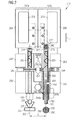
- FIG. 2 shows a side view of a placement head 207 according to an embodiment of the invention.
- the placement head 207 is a multiple placement head in which component fixtures are arranged in a regular matrix arrangement.
- Each holding device is in each case assigned a displacement device, so that all component holding devices can be displaced independently of one another along a common z-axis.
- FIG. 2 shows two displacement devices, a first displacement device 207a and a second displacement device 207b.
- the first displacement device 207a is shown in a side view and the second displacement device 207b in a sectional view.
- the two displacement devices 207a and 207b are arranged at a distance d from each other.
- the placement head 207 has a base element or a housing 208, which represents a frame structure for the correct arrangement of the individual components of the placement head 207.
- a housing 208 represents a frame structure for the correct arrangement of the individual components of the placement head 207.
- the housing 208 is shown only incomplete.
- a linear guide element 260 is rotatably mounted about a longitudinal axis 266.
- the linear guide element is a sleeve 260.
- the sleeve has a magnetic wheel 261 at its upper portion.
- Magnetic wheel 261 is a layered structure constructed along the longitudinal axis and having a layer of permanent magnetic material 261a.
- the permanent magnetic Layer 261a is sandwiched between two layers of a metallic material 261b, preferably iron.
- rotary actuators 263 are arranged, wherein in each case a rotary drive 263 of a displacement device 207a or 207b is assigned.
- the rotary drives 263 each have a drive wheel 264, which cooperates magnetically with one magnetic wheel 261 in such a way that upon rotation of the drive wheel 264, the corresponding magnetic wheel and thus also the sleeve 260 is rotated about the respective longitudinal axis 266.
- the sleeves 260 each have an opening extending along the longitudinal axis 266.
- an elongated shaft 265 is arranged, which is often referred to as quill.
- the elongate shaft 265 is slidably mounted within the opening along the z-direction.
- the elongate shaft 265 along a longitudinal section 268a has a gate 268, which can also be seen in the cross-sectional view perpendicular to the longitudinal axis 266, which cross-sectional view is shown in the bottom right in FIG .
- the elongate shaft 265 thus has an outer contour 269 which deviates from a cylindrical symmetry.
- a blocking element 268b is provided in the opening of the sleeve 260, so that, as a result, the inner contour of the sleeve 260 is shaped complementary to the outer contour 269. In this way, a displaceable, yet non-rotatable mounting of the elongate shaft 265 within the sleeve 260 is achieved.
- a component holding device 220 is disposed at the lower end of the elongated shaft 260, as shown at the lower left of FIG. 2, a component holding device 220 is disposed.
- the holding device is a suction pipette, which can hold an electronic component 225 when it is subjected to a negative pressure.
- the required to hold a device 225 negative pressure is transmitted via a vacuum intermediate chamber 292 and a suction channel 290 from a vacuum generating unit, not shown, to the suction pipette 220, which also has a suction channel, not shown.
- a recess 291 is provided on the outside of the shaft 265.
- the recess 291 extends along the longitudinal axis 266, so that regardless of the height position of the shaft 265 is always a part of the recess of an opening 293 of the vacuum intermediate chamber 292 facing. In this way, a continuous suction channel from the vacuum intermediate chamber 292 to the suction pipette 220 is always ensured.
- Each displacement device includes a return spring element 285 installed between the elongate shaft 265 and the sleeve 260 such that the elongate shaft 265 is urged by the spring force of the return spring element 285 into an upper starting position.
- a linear drive 275 is provided in the upper part of the placement head 207 for each elongate shaft. This has a along the z-axis slidable drive plunger 276, which presses against a top planar end face 267 of the shaft 265 in a downward movement. In this way, the shaft and attached holding device 220 can be moved down relative to the housing 208 of the placement head 207.
- the coupling element is a ball 280.
- the concern of the ball 280 on the flat end face 267 has the advantage that a low-friction point load can be realized. This can be realized between the non-rotatably mounted drive ram 276 and the shaft 265, a nearly punctiform mechanical contact and thus a largely frictionless rotation of the elongated shaft 265. In this way, the drive rod 276 and the elongated shaft 265 are almost completely decoupled with respect to rotational movements about the displacement axis and about the z-axis, respectively.
- a centric adjustment of the ball 280 is realized according to the embodiment shown here, characterized in that the ball 280 is fixed in a recess. As can be seen in FIG. 2, the recess is formed in a ball receiving element 277, which is located in the drive ram 276. As a result of the clamping action generated by the return spring 285 this adjustment remains reliable even during operation of the placement head 207.
- the recess may also be formed on the end face of the shaft 265.
- a point-shaped mechanical contact can also be realized in this case in a simple manner by the drive plunger 276 has a planar end face, which faces the ball.
- FIG. 3 shows a front view of the multiple placement head shown in FIG. 2, which is now designated by the reference numeral 307.
- three displacement devices, 307a, 307b and 307c are shown, which are arranged in a housing 308 of the placement at a distance d from each other.
- the rotationally secure mounting of an elongated shaft 365 in a sleeve 360 has already been explained above with reference to FIG.
- the rotary drives 363 are located in each case in front of the displacement axes 366.
- the drive wheels 364 of the rotary drives 363 can also be seen and the magnetic wheels, which, as already described in detail above, have a layer arrangement consisting of a permanent magnetic material 361a and a metallic material 361b.
- the area around the ball 380 is exposed, which ball 380 represents the coupling element and which rests against the flat end face 367 of the shaft 365.
- the arranged in the drive rod 376 of the linear actuator 375 ball receiving element 377, which has a recess for centering the ball 380 can be seen.
Landscapes
- Engineering & Computer Science (AREA)
- Manufacturing & Machinery (AREA)
- Microelectronics & Electronic Packaging (AREA)
- Supply And Installment Of Electrical Components (AREA)
- Automatic Assembly (AREA)
- Manipulator (AREA)
Applications Claiming Priority (1)
| Application Number | Priority Date | Filing Date | Title |
|---|---|---|---|
| DE102006046028A DE102006046028B4 (de) | 2006-09-28 | 2006-09-28 | Verschiebeeinrichtung für eine Bauelement-Haltevorrichtung mit zentraler Krafteinleitung |
Publications (2)
| Publication Number | Publication Date |
|---|---|
| EP1906723A2 true EP1906723A2 (fr) | 2008-04-02 |
| EP1906723A3 EP1906723A3 (fr) | 2010-01-27 |
Family
ID=38981003
Family Applications (1)
| Application Number | Title | Priority Date | Filing Date |
|---|---|---|---|
| EP07117023A Withdrawn EP1906723A3 (fr) | 2006-09-28 | 2007-09-24 | Dispositif de décalage pour un dispositif de support de composant doté d'une introduction de force centrale |
Country Status (2)
| Country | Link |
|---|---|
| EP (1) | EP1906723A3 (fr) |
| DE (1) | DE102006046028B4 (fr) |
Family Cites Families (6)
| Publication number | Priority date | Publication date | Assignee | Title |
|---|---|---|---|---|
| JPS6066500A (ja) * | 1983-09-22 | 1985-04-16 | 松下電器産業株式会社 | 部品装着装置 |
| US4611397A (en) * | 1984-10-09 | 1986-09-16 | Universal Instruments Corporation | Pick and place method and apparatus for handling electrical components |
| JP4082770B2 (ja) * | 1998-02-02 | 2008-04-30 | 富士機械製造株式会社 | 電気部品搬送装置ならびにそれにおける保持具交換方法および装置 |
| JP4034399B2 (ja) * | 1998-02-02 | 2008-01-16 | 松下電器産業株式会社 | 電子部品実装機のノズルユニット |
| DE60019596T2 (de) * | 1999-05-21 | 2006-03-02 | Matsushita Electric Industrial Co., Ltd., Kadoma | Hebevorrichtung mit saugdüse zum greifen von werkstücken |
| DE102005008584A1 (de) * | 2005-02-24 | 2006-09-07 | Aerolas Gmbh, Aerostatische Lager- Lasertechnik | Antriebseinheit für ein bewegbares Funktionselement |
-
2006
- 2006-09-28 DE DE102006046028A patent/DE102006046028B4/de not_active Expired - Fee Related
-
2007
- 2007-09-24 EP EP07117023A patent/EP1906723A3/fr not_active Withdrawn
Also Published As
| Publication number | Publication date |
|---|---|
| EP1906723A3 (fr) | 2010-01-27 |
| DE102006046028A1 (de) | 2008-04-10 |
| DE102006046028B4 (de) | 2013-06-06 |
Similar Documents
| Publication | Publication Date | Title |
|---|---|---|
| DE69608322T2 (de) | Vorrichtung zum Montieren von elektrischen und/oder elektronischen Bauteilen | |
| DE19503329C2 (de) | Testvorrichtung für elektronische Flachbaugruppen | |
| DE10020339A1 (de) | Vorrichtung zum Überführen von Leiterplatten bei einer Flächenmontagevorrichtung | |
| DE4301585A1 (en) | Mounting device for plugging electronic components into PCB - has mounting stations to position PCB in Y direction and mounting head movable in X direction and component stores at each station | |
| DE3919636A1 (de) | Geraet zur montage elektronischer komponenten | |
| EP2111092B1 (fr) | Tête à implanter, automate d'implantation, procédé destiné à aller chercher des composants et procédé destiné à implanter des substrats | |
| DE10019231B4 (de) | Vorrichtung zum Kompensieren der Niveauebene einer Leiterplatte für eine Flächenmontagevorrichtung | |
| DE102014103373B4 (de) | Bestückkopf mit zwei relativ zu einem Schaft beweglichen Gruppen von Pinolen, Bestückautomat und Verfahren zum Bestücken | |
| EP2073620A1 (fr) | Dispositif de transport de substrat pour un automate d'implantation | |
| DE102008010236B4 (de) | Vorrichtung zum Transportieren von Substraten bei einem Bestückautomaten, Bestückungsautomat und Verfahren zum Transportieren von Substraten | |
| DE102017116042B4 (de) | Verfahren und Bestückautomat zum Bestücken von Bauelementeträgern mit elektronischen Bauelementen | |
| DE4214384A1 (de) | Foerderanlage | |
| EP1954115B1 (fr) | Tête à implanter multiple dotée d'un entraînement rotatif collectif et d'un entraînement d'élévation mobile pour dispositifs de retenue de composants | |
| DE10004192B4 (de) | Mit einer Behälter-Beschickungseinrichtung versehene Flächenmontagevorrichtung | |
| DE102016114842B4 (de) | Bauelement-Haltevorrichtung, Verfahren und Computerprogramm zum Bestücken eines Bauelementeträgers, Bestückautomat | |
| DE102006046028B4 (de) | Verschiebeeinrichtung für eine Bauelement-Haltevorrichtung mit zentraler Krafteinleitung | |
| DE102008019101B4 (de) | Verfahren zum Bestücken von Substraten und Bestückautomat | |
| DE60300936T2 (de) | Automatische leiterplattenbestückvorrichtung mit einer leiterplattenpositioniereinrichtung | |
| EP1906722A2 (fr) | Système de positionnement avec axe linéaire précontraint magnétique | |
| WO2001057541A1 (fr) | Adaptateur pour verifier des cartes de circuits et aiguille de controle pour adaptateur de ce type | |
| DE112004001261B4 (de) | Verfahren zum aufnehmen von bauelementen mit hilfe einer bauelementbestückungsvorrichtung | |
| DE102008023614B3 (de) | Verfahren zum automatischen Positionieren von Unterstützungsstiften und Bestückautomat | |
| EP2009979A2 (fr) | Dispositif et procédé d'implantation de substrats à l'aide de composants | |
| DE102008046739B3 (de) | Pipette, Anordnung zum Kalibrieren einer wechselbaren Komponente, Positioniersystem, Bestückautomat sowie Messverfahren | |
| DE102004055719B4 (de) | Vorrichtung zum Bestücken von Bauelementeträgern mit Bauelementen |
Legal Events
| Date | Code | Title | Description |
|---|---|---|---|
| PUAI | Public reference made under article 153(3) epc to a published international application that has entered the european phase |
Free format text: ORIGINAL CODE: 0009012 |
|
| AK | Designated contracting states |
Kind code of ref document: A2 Designated state(s): AT BE BG CH CY CZ DE DK EE ES FI FR GB GR HU IE IS IT LI LT LU LV MC MT NL PL PT RO SE SI SK TR |
|
| AX | Request for extension of the european patent |
Extension state: AL BA HR MK YU |
|
| RAP1 | Party data changed (applicant data changed or rights of an application transferred) |
Owner name: SIEMENS ELECTRONICS ASSEMBLY SYSTEMS GMBH & CO. KG |
|
| PUAL | Search report despatched |
Free format text: ORIGINAL CODE: 0009013 |
|
| AK | Designated contracting states |
Kind code of ref document: A3 Designated state(s): AT BE BG CH CY CZ DE DK EE ES FI FR GB GR HU IE IS IT LI LT LU LV MC MT NL PL PT RO SE SI SK TR |
|
| AX | Request for extension of the european patent |
Extension state: AL BA HR MK RS |
|
| 17P | Request for examination filed |
Effective date: 20100719 |
|
| 17Q | First examination report despatched |
Effective date: 20100817 |
|
| AKX | Designation fees paid |
Designated state(s): AT BE BG CH CY CZ DE DK EE ES FI FR GB GR HU IE IS IT LI LT LU LV MC MT NL PL PT RO SE SI SK TR |
|
| RAP1 | Party data changed (applicant data changed or rights of an application transferred) |
Owner name: ASM ASSEMBLY SYSTEMS GMBH & CO. KG |
|
| GRAP | Despatch of communication of intention to grant a patent |
Free format text: ORIGINAL CODE: EPIDOSNIGR1 |
|
| STAA | Information on the status of an ep patent application or granted ep patent |
Free format text: STATUS: THE APPLICATION HAS BEEN WITHDRAWN |
|
| 18W | Application withdrawn |
Effective date: 20111125 |