EP1907048B1 - Retinaprothese mit separater zentraler elektrodenanordnung und peripherer elektrodenanordnung - Google Patents
Retinaprothese mit separater zentraler elektrodenanordnung und peripherer elektrodenanordnung Download PDFInfo
- Publication number
- EP1907048B1 EP1907048B1 EP06770017.9A EP06770017A EP1907048B1 EP 1907048 B1 EP1907048 B1 EP 1907048B1 EP 06770017 A EP06770017 A EP 06770017A EP 1907048 B1 EP1907048 B1 EP 1907048B1
- Authority
- EP
- European Patent Office
- Prior art keywords
- electrode array
- retinal prosthesis
- sclera
- resolution
- prosthesis according
- Prior art date
- Legal status (The legal status is an assumption and is not a legal conclusion. Google has not performed a legal analysis and makes no representation as to the accuracy of the status listed.)
- Expired - Lifetime
Links
Images

Classifications
-
- A—HUMAN NECESSITIES
- A61—MEDICAL OR VETERINARY SCIENCE; HYGIENE
- A61N—ELECTROTHERAPY; MAGNETOTHERAPY; RADIATION THERAPY; ULTRASOUND THERAPY
- A61N1/00—Electrotherapy; Circuits therefor
- A61N1/02—Details
- A61N1/04—Electrodes
- A61N1/05—Electrodes for implantation or insertion into the body, e.g. heart electrode
- A61N1/0526—Head electrodes
- A61N1/0543—Retinal electrodes
-
- A—HUMAN NECESSITIES
- A61—MEDICAL OR VETERINARY SCIENCE; HYGIENE
- A61F—FILTERS IMPLANTABLE INTO BLOOD VESSELS; PROSTHESES; DEVICES PROVIDING PATENCY TO, OR PREVENTING COLLAPSING OF, TUBULAR STRUCTURES OF THE BODY, e.g. STENTS; ORTHOPAEDIC, NURSING OR CONTRACEPTIVE DEVICES; FOMENTATION; TREATMENT OR PROTECTION OF EYES OR EARS; BANDAGES, DRESSINGS OR ABSORBENT PADS; FIRST-AID KITS
- A61F9/00—Methods or devices for treatment of the eyes; Devices for putting in contact-lenses; Devices to correct squinting; Apparatus to guide the blind; Protective devices for the eyes, carried on the body or in the hand
- A61F9/08—Devices or methods enabling eye-patients to replace direct visual perception by another kind of perception
-
- A—HUMAN NECESSITIES
- A61—MEDICAL OR VETERINARY SCIENCE; HYGIENE
- A61N—ELECTROTHERAPY; MAGNETOTHERAPY; RADIATION THERAPY; ULTRASOUND THERAPY
- A61N1/00—Electrotherapy; Circuits therefor
- A61N1/18—Applying electric currents by contact electrodes
- A61N1/32—Applying electric currents by contact electrodes alternating or intermittent currents
- A61N1/36—Applying electric currents by contact electrodes alternating or intermittent currents for stimulation
- A61N1/36046—Applying electric currents by contact electrodes alternating or intermittent currents for stimulation of the eye
Definitions
- the present invention is generally directed to a visual prosthesis and more specifically to an improved mechanical and electrical configuration for retinal prosthesis for artificial vision.
- LeRoy passed the discharge of a Leyden jar through the orbit of a man who was blind from cataract and the patient saw "flames passing rapidly downwards.”
- the general concept of electrical stimulation of retinal cells to produce these flashes of light or phosphenes has been known for quite some time.
- some early attempts at devising a prosthesis for aiding the visually impaired have included attaching electrodes to the head or eyelids of patients. While some of these early attempts met with some limited success, these early prosthetic devices were large, bulky and could not produce adequate simulated vision to truly aid the visually impaired.
- Foerster investigated the effect of electrically stimulating the exposed occipital pole of one cerebral hemisphere. He found that, when a point at the extreme occipital pole was stimulated, the patient perceived a small spot of light directly in front and motionless (a phosphene). Subsequently, Brindley and Lewin (1968) thoroughly studied electrical stimulation of the human occipital (visual) cortex. By varying the stimulation parameters, these investigators described in detail the location of the phosphenes produced relative to the specific region of the occipital cortex stimulated. These experiments demonstrated: (1) the consistent shape and position of phosphenes; (2) that increased stimulation pulse duration made phosphenes brighter; and (3) that there was no detectable interaction between neighboring electrodes which were as close as 2.4 mm apart.
- Neural tissue can be artificially stimulated and activated by prosthetic devices that pass pulses of electrical current through electrodes on such a device.
- the passage of current causes changes in electrical potentials across visual neuronal membranes, which can initiate visual neuron action potentials, which are the means of information transfer in the nervous system.
- neural tissue stimulation is in the rehabilitation of the blind.
- Some forms of blindness involve selective loss of the light sensitive transducers of the retina.
- Other retinal neurons remain viable, however, and may be activated in the manner described above by placement of a prosthetic electrode device on the inner (toward the vitreous) retinal surface (epiretinal). This placement must be mechanically stable, minimize the distance between the device electrodes and the visual neurons, and avoid undue compression of the visual neurons.
- Bullara US Pat. No. 4,573,481 patented an electrode assembly for surgical implantation on a nerve.
- the matrix was silicone with embedded iridium electrodes.
- the assembly fit around a nerve to stimulate it.
- the Michelson '933 apparatus includes an array of photosensitive devices on its surface that are connected to a plurality of electrodes positioned on the opposite surface of the device to stimulate the retina. These electrodes are disposed to form an array similar to a "bed of nails" having conductors which impinge directly on the retina to stimulate the retinal cells.
- US Patents 4,837,049 to Byers describes spike electrodes for neural stimulation. Each spike electrode pierces neural tissue for better electrical contact.
- US Patent 5,215,088 to Normann describes an array of spike electrodes for cortical stimulation. Each spike pierces cortical tissue for better electrical contact.
- Humayun US Patent 5,935,155 describes the use of retinal tacks to attach a retinal array to the retina.
- an electrode array may be attached by magnets or glue.
- US Patent 5,109,844 to de Juan describes a flat electrode array placed against the retina for visual stimulation.
- DE102004032004 A1 discloses a visual aiding device for restoring vision of a patient comprising a plurality of substrates which are placed under a retina of a patient's eye.
- our peripheral vision detects movement we move first our eyes, and then our heads toward the movement, detecting the object with our fovea. This happens so quickly and automatically, that we are generally unaware of the lower resolution in the periphery. Further, we tend to scan a scene and our brain remembers details after they are scanned by the fovea. This gives us the perception of continuous high-resolution vision.
- Photolithographic techniques are the best know technique for creating an electrode array that approaches the natural resolution of the fovea.
- photolithographic techniques require that the array be made flat, not curved like the retina.
- Other techniques such a silicone molding over hand welded wires are easily made curved, but can not produce the high-resolution of a photolithographic array.
- the artificial percept of light may be created by electrically stimulating the neurons of the retina. While a photolithographed array internal to the retina provides superior resolution, an array external to the retina provides easier implantation and improved manufacturability. Therefore it is advantageous to supply a high-resolution electrode array internal to the sclera, near the fovea and a lower-resolution electrode array eternal to the sclera near the periphery of the retina.
- the preferred method of manufacturing a high-resolution electrode array is through photolithography, which requires the array to be made flat. While it is possible to curve the array afterward, it is difficult and costly.
- I small high-resolution array can be implanted near the fovea. Due to its small size, curvature is less of an issue.
- a larger lower-resolution array can be molded in silicone or similar method and placed around the periphery, of the retina, where the retina is naturally lower-resolution. Further, the lower-resolution array is implanted external to the sclera reducing the number of electrical connectors passing through the sclera.
- FIG. 1 shows a perspective view of the implanted portion of the preferred retinal prosthesis.
- a high-resolution electrode array 10 is mounted by a retinal tack or similar means to the epiretinal surface near the fovea.
- the high-resolution electrode array 10 is electrically coupled by a cable 12, which pierces the sclera and is electrically coupled to an electronics package 14, external to the sclera.
- the electronics package 14 is electrically coupled to a secondary inductive coil 16.
- the secondary inductive coil 16 is made from wound wire.
- the secondary inductive coil may be made from a thin film polymer sandwich with wire traces deposited between layers of thin film polymer.
- the electronics package 14 and secondary inductive coil 16 are held together by a molded body 18.
- the molded body 18 may also include suture tabs 20.
- the molded body narrows to form a strap 22, which surrounds the sclera and holds the molded body 18, secondary inductive coil 16, and electronics package 14 in place.
- the strap 22 further supports a lower-resolution electrode array 30, mounted external to the sclera.
- the lower-resolution electrode array 30 surrounds the peripheral retina and supports electrodes for stimulating percepts in the periphery of the retina.
- the external electrode array is preferable molded of silicone in a curved shape and highly flexible.
- the molded body 18, suture tabs 20 strap 22 and lower-resolution electrode array 30 are preferably an integrated unit made of silicone elastomer. Silicone elastomer can be formed in a pre-curved shape to match the curvature of a typical sclera. However, silicone remains flexible enough to accommodate implantation and to adapt to variations in the curvature and size of an individual sclera.
- the secondary inductive coil 16 and molded body 18 are preferably oval shaped. A strap can better support an oval shaped coil.
- the lower-resolution array 30 may be integrally molded into the strap 22 or a separate structure, which passes under the strap 22.
- the lower-resolution electrode array 30 may extend both in front of the strap to the pars plana and behind the strap to cover all of the retina leaving a gap 32 over that portion of the retina stimulated by the high-resolution electrode array and the optic nerve.
- the lower-resolution electrode array extends beyond the portion of the strap 22 that passes through the buckle 23, to provide full 360° stimulation.
- the lower-resolution electrode array 30 may overlap itself to accommodate different size scleras. After implantation, overlapping electrodes may be disabled. Particularly, if the lower-resolution electrode array 30 is separate from the strap 22, it would be advantageous to provide suture tabs 34 directly on the lower-resolution electrode array 30.
- the entire implant is attached to and supported by the sclera.
- An eye moves constantly. The eye moves to scan a scene and also has a jitter motion to improve acuity. Even though such motion is useless in the blind, it often continues long after a person has lost their sight.
- the lower-resolution electrode array 30 though mounted externally, must move with the retina to give a consistent visual image. Also, by placing the device under the rectus muscles with the electronics package in an area of fatty issue between the rectus muscles, eye motion does not cause any flexing which might fatigue, and eventually damage, the device.
- a remote return or common electrode for each electrode array on the opposite side of the retina from the electrode array, thereby causing current to flow through the retina.
- the outer case of the electronics package 14 provides a remote return electrode.
- remote return electrode 36 may be placed internal to the eye.
- the lower-resolution electrode array 30 may provide the remote return electrode for the high-resolution array 10
- the high-resolution array 10 may provide the remote return electrode for the lower-resolution array 30.
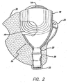
- Figure 2 shows a side view of the implanted portion of the retinal prosthesis, in particular, emphasizing the fan-tail 24 and the shape of the lower-resolution electrode array 30.
- the secondary inductive coil 16 and molded body 18 must also follow the strap under the lateral rectus muscle on the side of the sclera.
- the implanted portion of the retinal prosthesis is very delicate. It is easy to tear the molded body 18 or break wires in the secondary inductive coil 16. In order to allow the molded body 18 to slide smoothly under the lateral rectus muscle, the molded body is shaped in the form of a fan tail 24 on the end opposite the electronics package 14.
- Reinforced attachment points are provided to facilitate handling of the retinal prosthesis by surgical tools.
- the reinforced attachment points are harder silicone formed around holes through the molded body 18.
- a hook 28 is molded into the strap 22 just beyond the end of the fan tail 24. A surgical tool can be used against the hook 28 to push the strap 22 under the rectus muscles.
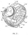
- the hook 28 is more clearly depicted by the edge view of Figure 3 .
- the strap 22 is attached to itself by a sleeve 23.
- the sleeve 23 is a friction device that connects two silicone bands and holds them together with friction.
- the sleeve 23 is similar to a Watzke sleeve, used with a scleral buckle, and is well known in the art.
- the high-resolution electrode array 10 and cable 12 are formed layers of a thin polymer film with metal traces sandwiched between the thin polymer films.
- the film with openings for high-resolution electrode array 10 be the same film with an opening for connection to the electronics package 14. Therefore, the cable 12 exits the electronics package up away from the fantail 24, folds over itself and exits down toward the fantail 24, before turning at a right angle and piercing the sclera. This allows the same side of the cable to face both the electronics package and the retina.
- the cable 12 may also include a fantail at the point it is attached to the electronics package 14 and at the point it is attached to the high-resolution electrode array 10 to reduce any stress on the connections that may be caused by implantation. It is important that the cable exit the molded body 18 toward the front or the eye. The cable must travel above the lateral rectus muscle and pierce the sclera at the pars plana, in front of the retina, so it does not damage the retina. Once inside the eye, the cable 12 can fold back over the retina to properly locate the high-resolution electrode array 10 on the epiretinal surface.
- the lower the resolution of the array the easier it is to form the array to shape of the retina. While described here as two arrays, one higher resolution and less flexible, and one lower-resolution and more flexible, it possible to use more than two arrays using more than two array technologies. Its is also possible to use the same array technology and tile segments to achieve a rounder overall shape. With thin film technology curving the array, after deposition of the metal traces can cause the traces to break. Hence, the prosthesis may provide a high-resolution array, a middle resolution array and a lower-resolution array or even more variations.
- the lower resolution electrode array may be a photolithographically-made thin film array. While it is difficult to curve a thin film in two dimensions to follow the spherical shape of the retina, it is easy to curve a thin film in one dimension, such as a cylinder. Hence, a thin film can be used to make a generally cylindrical array around the periphery of the retina, either externally or internally to the retina.
- the lower-resolution array 130 may be tiled small sections of thin film arrays.
- a high-resolution electrode array 110 is mounted by a retinal tack or similar means to the epiretinal surface near the fovea.
- the high-resolution electrode array 110 is electrically coupled by a cable 112, which pierces the sclera and is electrically coupled to an electronics package 114, external to the sclera.
- the electronics package 114 is electrically coupled to a secondary inductive coil 16.
- the electronics package 114 and secondary inductive coil 116 are held together by a molded body 118 .
- the molded body 118 may also include suture tabs 120 .
- the molded body narrows to form a strap 122, which surrounds the sclera and holds the molded body 118, secondary inductive coil 116, and electronics package 114 in place.
- the strap 122 further supports a lower-resolution electrode array 130, mounted external to the sclera.
- the lower-resolution electrode array 130 surrounds the peripheral retina and supports electrodes for stimulating percepts in the periphery of the retina.
- the lower-resolution electrode array is preferable tiled sections of thin film array, which are sufficiently small that they conform to the curvature of the retina.
- the lower-resolution electrode array 130 may extend both in front of the strap to the pars plana and behind the strap to cover the entire retina leaving a gap 132 over that portion of the retina stimulated by the high-resolution electrode array and the optic nerve. Ideally, the lower-resolution electrode array extends beyond the portion of the strap 122 that passes through the buckle to provide full 360° stimulation.
- the lower-resolution electrode array 130 may overlap itself to accommodate different size scleras. After implantation, overlapping electrodes may be disabled. Particularly, if the lower-resolution electrode array 130 is separate from the strap 122, it would be advantageous to provide suture tabs 134 directly on the lower-resolution electrode array 130.
- implantation methods include epi-retinal, sub-retinal, super-choroidal, intra-scleral and extrascleral.
- Epi-retinal is on the inner retinal surface in the vitreous humor.
- Sub-retinal is on the outer retinal surface between the retina and the choroid.
- Super-choroidal is between the choroid and sclera.
- Intra-scleral in within the layers of the sclera.
- Extra-scleral is outside the sclera.
Landscapes
- Health & Medical Sciences (AREA)
- Life Sciences & Earth Sciences (AREA)
- Public Health (AREA)
- Veterinary Medicine (AREA)
- Engineering & Computer Science (AREA)
- Biomedical Technology (AREA)
- Ophthalmology & Optometry (AREA)
- General Health & Medical Sciences (AREA)
- Animal Behavior & Ethology (AREA)
- Radiology & Medical Imaging (AREA)
- Nuclear Medicine, Radiotherapy & Molecular Imaging (AREA)
- Heart & Thoracic Surgery (AREA)
- Cardiology (AREA)
- Vascular Medicine (AREA)
- Prostheses (AREA)
- Electrotherapy Devices (AREA)
Claims (17)
- Retinaprothese, umfassend:eine hochauflösende Elektrodenanordnung (10, 110), die dazu geeignet ist, um innerhalb der Sklera in unmittelbarer Nähe einer Sehgrube einer Retina montiert zu werden;eine Elektrodenanordnung mit niedrigerer Auflösung (30, 130), die dazu geeignet ist, um außen an der Sklera um den Umfang der Retina herum montiert zu werden; undimplantierbare Elektronik (14, 114), um die hochauflösende Elektrodenanordnung und die Elektronenanordnung mit niedrigerer Auflösung anzusteuern.
- Retinaprothese nach Anspruch 1, worin die hochauflösende Elektrodenanordnung (10, 110) dazu geeignet ist, an einer epiretinalen Stelle montiert zu werden.
- Retinaprothese nach Anspruch 1, worin die hochauflösende Elektrodenanordnung (10, 110) dazu geeignet ist, an einer subretinalen Stelle montiert zu werden.
- Retinaprothese nach einem der vorangehenden Ansprüche, worin die hochauflösende Elektrodenanordnung (10, 110) aus einem Dünnfilmpolymer mit Metallbahnen besteht, die in einem Fotolithografieverfahren ausgebildet wurden.
- Retinaprothese nach einem der vorangehenden Ansprüche, worin die Anordnung mit niedrigerer Auflösung (30, 130) aus in Silikon geformtem Draht gebildet wird.
- Retinaprothese nach einem der vorangehenden Ansprüche, worin die Anordnung mit niedrigerer Auflösung (30) in einer einzigen Einheit (18) mit der implantierbaren Elektronik ausgebildet ist.
- Retinaprothese nach einem der vorangehenden Ansprüche, welche ferner Nahtlaschen (20, 120, 34, 134) umfasst, die mit der Elektronikeinheit verbunden und dazu geeignet sind, die Elektronikeinheit an einer Sklera zu befestigen.
- Retinaprothese nach einem der vorangehenden Ansprüche, worin
die implantierbare Elektronik (14, 114) eine Elektronikeinheit ist, die geeignet ist, um außen an der Sklera montiert zu werden; und worin die Retinaprothese ferner Folgendes umfasst:ein elektrisches Kabel (12, 112), welches die hochauflösende Elektrodenanordnung mit der Elektronikeinheit koppelt; undeine sekundäre Induktionsspule (16, 116), die elektrisch mit der Elektronikeinheit gekoppelt und dazu geeignet ist, an der Seite einer Sklera montiert zu werden. - Retinaprothese nach Anspruch 8, worin das Kabel (12, 112) und die hochauflösende Elektrodenanordnung (10, 110) Metallbahnen umfassen, die zwischen dünnen Polymerfilmen sandwichartig angeordnet sind.
- Retinaprothese nach Anspruch 8 oder 9, welche ferner ein Gurtband (22, 122) umfasst, welches mit der sekundären Induktionsspule (16, 116) verbunden und dazu geeignet ist, die Sklera zu umgeben.
- Retinaprothese nach einem der Ansprüche 8-10, welche ferner ein Gurtband (22, 122) umfasst, welches mit der Elektrodenanordnung mit niedrigerer Auflösung (30, 130) verbunden und dazu geeignet ist, die Sklera zu umgeben.
- Retinaprothese nach einem der Ansprüche 8-11, welche ferner ein Gurtband (22, 122) umfasst, welches mit der Elektronikeinheit (14, 114) verbunden und dazu geeignet ist, die Sklera zu umgeben.
- Retinaprothese nach einem der Ansprüche 8-12, welche ferner Nahtlaschen (20, 120) umfasst, die mit der sekundären Induktionsspule (16, 116) verbunden und dazu geeignet sind, die sekundäre Induktionsspule an einer Sklera zu befestigen.
- Retinaprothese nach einem der Ansprüche 8-13, worin das Kabel gefaltet ist, um sowohl der Elektronikeinheit als auch der Retina dieselbe Seite des Kabels zu präsentieren.
- Retinaprothese nach einem der Ansprüche 8-14, worin das elektrische Kabel (12, 112) dazu geeignet ist, die Pars-Plana-Region der Sklera zu durchstoßen.
- Retinaprothese nach einem der Ansprüche 8-15, welche ferner eine Elektrodenanordnung mit mittlerer Auflösung umfasst, die dazu geeignet ist, nahe einer mittleren Region der Retina implantiert zu werden.
- Retinaprothese nach einem der Ansprüche 8-16, worin
die Elektrodenanordnung mit niedrigerer Auflösung (130) eine Vielzahl geneigter Elektrodenanordnungen mit niedrigerer Auflösung (130) ist, die dazu geeignet sind, in unmittelbarer Nähe zu dem Umfang der Retina montiert zu werden.
Applications Claiming Priority (2)
| Application Number | Priority Date | Filing Date | Title |
|---|---|---|---|
| US67755105P | 2005-05-04 | 2005-05-04 | |
| PCT/US2006/017282 WO2006119468A2 (en) | 2005-05-04 | 2006-05-04 | Retinal prosthesis with separate central electrode array and peripheral electrode array |
Publications (2)
| Publication Number | Publication Date |
|---|---|
| EP1907048A2 EP1907048A2 (de) | 2008-04-09 |
| EP1907048B1 true EP1907048B1 (de) | 2016-08-31 |
Family
ID=36956069
Family Applications (1)
| Application Number | Title | Priority Date | Filing Date |
|---|---|---|---|
| EP06770017.9A Expired - Lifetime EP1907048B1 (de) | 2005-05-04 | 2006-05-04 | Retinaprothese mit separater zentraler elektrodenanordnung und peripherer elektrodenanordnung |
Country Status (5)
| Country | Link |
|---|---|
| US (4) | US7904163B2 (de) |
| EP (1) | EP1907048B1 (de) |
| JP (1) | JP4913132B2 (de) |
| AU (1) | AU2006243786B2 (de) |
| WO (1) | WO2006119468A2 (de) |
Families Citing this family (32)
| Publication number | Priority date | Publication date | Assignee | Title |
|---|---|---|---|---|
| WO2006119468A2 (en) * | 2005-05-04 | 2006-11-09 | Second Sight Medical Products, Inc. | Retinal prosthesis with separate central electrode array and peripheral electrode array |
| US7877866B1 (en) * | 2005-10-26 | 2011-02-01 | Second Sight Medical Products, Inc. | Flexible circuit electrode array and method of manufacturing the same |
| US7831309B1 (en) | 2006-12-06 | 2010-11-09 | University Of Southern California | Implants based on bipolar metal oxide semiconductor (MOS) electronics |
| WO2009006636A2 (en) * | 2007-07-05 | 2009-01-08 | Second Sight Medical Products | Return electrode for a flexible circuit electrode array |
| AU2008282451B2 (en) | 2007-07-27 | 2013-09-26 | Second Sight Medical Products | Implantable device for the brain |
| US8874235B1 (en) | 2008-12-12 | 2014-10-28 | Greatbatch Ltd. | Self fixing spinal cord stimulation paddle lead |
| EP2424476B1 (de) * | 2009-04-27 | 2014-05-07 | National ICT Australia Limited | Retinaprothese |
| US9950166B2 (en) | 2009-10-20 | 2018-04-24 | Nyxoah SA | Acred implant unit for modulation of nerves |
| US10751537B2 (en) | 2009-10-20 | 2020-08-25 | Nyxoah SA | Arced implant unit for modulation of nerves |
| US9409013B2 (en) | 2009-10-20 | 2016-08-09 | Nyxoah SA | Method for controlling energy delivery as a function of degree of coupling |
| JP5812259B2 (ja) * | 2011-05-31 | 2015-11-11 | 株式会社ニデック | 視覚再生補助装置 |
| US9907967B2 (en) | 2012-07-26 | 2018-03-06 | Adi Mashiach | Transcutaneous power conveyance device |
| US10052097B2 (en) | 2012-07-26 | 2018-08-21 | Nyxoah SA | Implant unit delivery tool |
| US8948871B2 (en) | 2012-07-26 | 2015-02-03 | Nyxoah SA | Electrical contacts on a medical device patch |
| US11253712B2 (en) | 2012-07-26 | 2022-02-22 | Nyxoah SA | Sleep disordered breathing treatment apparatus |
| US9248302B2 (en) | 2013-06-17 | 2016-02-02 | Adi Mashiach | Residual signal feedback-based control of an implant |
| US11628038B2 (en) | 2020-02-21 | 2023-04-18 | Raytrx, Llc | Multi-option all-digital 3D surgery visualization system and control |
| US11956414B2 (en) | 2015-03-17 | 2024-04-09 | Raytrx, Llc | Wearable image manipulation and control system with correction for vision defects and augmentation of vision and sensing |
| US9955862B2 (en) | 2015-03-17 | 2018-05-01 | Raytrx, Llc | System, method, and non-transitory computer-readable storage media related to correction of vision defects using a visual display |
| US11461936B2 (en) | 2015-03-17 | 2022-10-04 | Raytrx, Llc | Wearable image manipulation and control system with micro-displays and augmentation of vision and sensing in augmented reality glasses |
| US11016302B2 (en) | 2015-03-17 | 2021-05-25 | Raytrx, Llc | Wearable image manipulation and control system with high resolution micro-displays and dynamic opacity augmentation in augmented reality glasses |
| CN109925092B (zh) * | 2017-12-18 | 2025-04-01 | 深圳先进技术研究院 | 硅胶封装的人造视网膜植入体 |
| AU2019352954B2 (en) | 2018-10-01 | 2022-03-10 | I-Lumen Scientific, Inc. | System and methods for controlled electrical modulation for vision therapy |
| US11305118B2 (en) | 2018-11-30 | 2022-04-19 | Biovisics Medical, Inc. | Head worn apparatuses for vision therapy |
| US11471680B2 (en) | 2019-04-10 | 2022-10-18 | Biovisics, Inc. | Systems and interfaces for ocular therapy |
| ES2992491T3 (es) | 2019-06-14 | 2024-12-13 | I Lumen Scient Inc | Dispositivo médico portátil |
| US12023498B2 (en) | 2019-07-12 | 2024-07-02 | Biovisics Medical, Inc. | Ocular therapy modes and systems |
| US12142367B2 (en) | 2020-02-21 | 2024-11-12 | Raytrx, Llc | Surgery visualization theatre |
| US11916156B2 (en) | 2020-04-09 | 2024-02-27 | The Hong Kong University Of Science And Technology | Method and system for optical detection using a biomimetic electrochemical eye |
| CN111588984B (zh) * | 2020-05-27 | 2021-02-19 | 微智医疗器械有限公司 | 植入式视网膜电刺激器及其植入体 |
| US12702831B2 (en) | 2022-09-29 | 2026-08-11 | I-Lumen Scientific, Inc. | Systems and methods to manage microcurrent therapy dose |
| US12589243B2 (en) | 2022-10-21 | 2026-03-31 | I-Lumen Scientific, Inc. | Ocular devices and controller interfaces for ocular therapy |
Family Cites Families (24)
| Publication number | Priority date | Publication date | Assignee | Title |
|---|---|---|---|---|
| US4573481A (en) | 1984-06-25 | 1986-03-04 | Huntington Institute Of Applied Research | Implantable electrode array |
| US4628933A (en) | 1985-07-23 | 1986-12-16 | Michelson Robin P | Method and apparatus for visual prosthesis |
| US4837049A (en) | 1986-06-17 | 1989-06-06 | Alfred E. Mann Foundation For Scientific Research | Method of making an electrode array |
| US5215088A (en) | 1989-11-07 | 1993-06-01 | The University Of Utah | Three-dimensional electrode device |
| US5109844A (en) | 1990-10-11 | 1992-05-05 | Duke University | Retinal microstimulation |
| DE19707046A1 (de) * | 1997-02-21 | 1998-08-27 | Rolf Prof Dr Ing Eckmiller | Lernfähiger "Active Vision" Implant Encoder |
| US6458157B1 (en) * | 1997-08-04 | 2002-10-01 | Suaning Gregg Joergen | Retinal stimulator |
| US5935155A (en) * | 1998-03-13 | 1999-08-10 | John Hopkins University, School Of Medicine | Visual prosthesis and method of using same |
| JP3599237B2 (ja) * | 1999-05-07 | 2004-12-08 | エベルハルト・カルルス・ウニヴェルズィテート テュービンゲン ウニヴェルズィテートクリニク | 網膜インプラントおよびその製造方法 |
| US7103416B2 (en) * | 2001-01-16 | 2006-09-05 | Second Sight Medical Products, Inc. | Visual prosthesis including enhanced receiving and stimulating portion |
| US7149586B2 (en) | 2002-03-28 | 2006-12-12 | Second Sight Medical Products, Inc. | Variable pitch electrode array |
| US7338522B2 (en) | 2001-02-13 | 2008-03-04 | Second Sight Medical Products, Inc. | Implantable retinal electrode array configuration for minimal retinal damage and method of reducing retinal stress |
| US20040106965A1 (en) * | 2001-06-29 | 2004-06-03 | Chow Alan Y. | Methods and apparatus for treatment of degenerative retinal disease via indirect electrical stimulation |
| US7003355B1 (en) * | 2001-11-20 | 2006-02-21 | Suaning Gregg J | Vision prosthesis for the blind and method for implementing same |
| US6976998B2 (en) * | 2002-01-17 | 2005-12-20 | Massachusetts Institute Of Technology | Minimally invasive retinal prosthesis |
| US6718209B2 (en) * | 2002-02-05 | 2004-04-06 | Second Sight Medical Products, Inc. | Retinal prosthesis with remote return electrode |
| US7211103B2 (en) * | 2002-04-11 | 2007-05-01 | Second Sight Medical Products, Inc. | Biocompatible bonding method and electronics package suitable for implantation |
| US7142909B2 (en) * | 2002-04-11 | 2006-11-28 | Second Sight Medical Products, Inc. | Biocompatible bonding method and electronics package suitable for implantation |
| US7005179B2 (en) * | 2002-07-26 | 2006-02-28 | The Regents Of The University Of California | Conductive inks for metalization in integrated polymer microsystems |
| JP4162526B2 (ja) * | 2003-03-31 | 2008-10-08 | 株式会社ニデック | 視覚再生補助装置 |
| US7571011B2 (en) * | 2003-05-01 | 2009-08-04 | Second Sight Medical Products, Inc. | Adherent metal oxide coating forming a high surface area electrode |
| JP4412924B2 (ja) * | 2003-07-01 | 2010-02-10 | 株式会社ニデック | 視覚再生補助装置 |
| US7228181B2 (en) * | 2004-04-06 | 2007-06-05 | Second Sight Medical Products, Inc. | Retinal prosthesis with side mounted inductive coil |
| WO2006119468A2 (en) * | 2005-05-04 | 2006-11-09 | Second Sight Medical Products, Inc. | Retinal prosthesis with separate central electrode array and peripheral electrode array |
-
2006
- 2006-05-04 WO PCT/US2006/017282 patent/WO2006119468A2/en not_active Ceased
- 2006-05-04 JP JP2008510234A patent/JP4913132B2/ja not_active Expired - Fee Related
- 2006-05-04 US US11/418,677 patent/US7904163B2/en active Active
- 2006-05-04 AU AU2006243786A patent/AU2006243786B2/en not_active Ceased
- 2006-05-04 EP EP06770017.9A patent/EP1907048B1/de not_active Expired - Lifetime
-
2007
- 2007-10-25 US US11/924,458 patent/US8036752B2/en not_active Expired - Fee Related
-
2011
- 2011-09-07 US US13/227,132 patent/US8886329B2/en not_active Expired - Lifetime
-
2014
- 2014-10-16 US US14/516,466 patent/US9636496B2/en not_active Expired - Fee Related
Also Published As
| Publication number | Publication date |
|---|---|
| US20150039067A1 (en) | 2015-02-05 |
| US9636496B2 (en) | 2017-05-02 |
| JP2008539891A (ja) | 2008-11-20 |
| US20120004704A1 (en) | 2012-01-05 |
| WO2006119468A2 (en) | 2006-11-09 |
| US7904163B2 (en) | 2011-03-08 |
| US8036752B2 (en) | 2011-10-11 |
| WO2006119468A3 (en) | 2006-12-21 |
| JP4913132B2 (ja) | 2012-04-11 |
| AU2006243786B2 (en) | 2011-12-22 |
| US20080046032A1 (en) | 2008-02-21 |
| US8886329B2 (en) | 2014-11-11 |
| AU2006243786A1 (en) | 2006-11-09 |
| US20060253172A1 (en) | 2006-11-09 |
| EP1907048A2 (de) | 2008-04-09 |
Similar Documents
| Publication | Publication Date | Title |
|---|---|---|
| US8036752B2 (en) | Retinal prosthesis with separate central electrode array and peripheral electrode array | |
| EP2219728B1 (de) | Elektrodenanordnung für gleichmässigen neuralen druck mit mehreren befestigungspunkten | |
| US7228181B2 (en) | Retinal prosthesis with side mounted inductive coil | |
| US8014878B2 (en) | Flexible circuit electrode array | |
| AU2007261319B2 (en) | Flexible circuit electrode array with at least one tack opening | |
| AU2008272808B2 (en) | Return electrode for a flexible circuit electrode array | |
| AU2012201442B2 (en) | Retinal prosthesis with separate central electrode array and peripheral electrode array |
Legal Events
| Date | Code | Title | Description |
|---|---|---|---|
| PUAI | Public reference made under article 153(3) epc to a published international application that has entered the european phase |
Free format text: ORIGINAL CODE: 0009012 |
|
| 17P | Request for examination filed |
Effective date: 20071128 |
|
| AK | Designated contracting states |
Kind code of ref document: A2 Designated state(s): AT BE BG CH CY CZ DE DK EE ES FI FR GB GR HU IE IS IT LI LT LU LV MC NL PL PT RO SE SI SK TR |
|
| DAX | Request for extension of the european patent (deleted) | ||
| 17Q | First examination report despatched |
Effective date: 20121213 |
|
| GRAP | Despatch of communication of intention to grant a patent |
Free format text: ORIGINAL CODE: EPIDOSNIGR1 |
|
| INTG | Intention to grant announced |
Effective date: 20151118 |
|
| REG | Reference to a national code |
Ref country code: DE Ref legal event code: R079 Ref document number: 602006050132 Country of ref document: DE Free format text: PREVIOUS MAIN CLASS: A61N0001360000 Ipc: A61B0001015000 |
|
| GRAP | Despatch of communication of intention to grant a patent |
Free format text: ORIGINAL CODE: EPIDOSNIGR1 |
|
| RIC1 | Information provided on ipc code assigned before grant |
Ipc: A61B 1/015 20060101AFI20160301BHEP |
|
| INTG | Intention to grant announced |
Effective date: 20160315 |
|
| GRAS | Grant fee paid |
Free format text: ORIGINAL CODE: EPIDOSNIGR3 |
|
| GRAA | (expected) grant |
Free format text: ORIGINAL CODE: 0009210 |
|
| AK | Designated contracting states |
Kind code of ref document: B1 Designated state(s): AT BE BG CH CY CZ DE DK EE ES FI FR GB GR HU IE IS IT LI LT LU LV MC NL PL PT RO SE SI SK TR |
|
| REG | Reference to a national code |
Ref country code: CH Ref legal event code: EP Ref country code: GB Ref legal event code: FG4D |
|
| REG | Reference to a national code |
Ref country code: IE Ref legal event code: FG4D |
|
| REG | Reference to a national code |
Ref country code: DE Ref legal event code: R096 Ref document number: 602006050132 Country of ref document: DE |
|
| REG | Reference to a national code |
Ref country code: AT Ref legal event code: REF Ref document number: 824208 Country of ref document: AT Kind code of ref document: T Effective date: 20161015 |
|
| REG | Reference to a national code |
Ref country code: LT Ref legal event code: MG4D |
|
| REG | Reference to a national code |
Ref country code: NL Ref legal event code: MP Effective date: 20160831 |
|
| REG | Reference to a national code |
Ref country code: AT Ref legal event code: MK05 Ref document number: 824208 Country of ref document: AT Kind code of ref document: T Effective date: 20160831 |
|
| PG25 | Lapsed in a contracting state [announced via postgrant information from national office to epo] |
Ref country code: FI Free format text: LAPSE BECAUSE OF FAILURE TO SUBMIT A TRANSLATION OF THE DESCRIPTION OR TO PAY THE FEE WITHIN THE PRESCRIBED TIME-LIMIT Effective date: 20160831 Ref country code: LT Free format text: LAPSE BECAUSE OF FAILURE TO SUBMIT A TRANSLATION OF THE DESCRIPTION OR TO PAY THE FEE WITHIN THE PRESCRIBED TIME-LIMIT Effective date: 20160831 |
|
| PG25 | Lapsed in a contracting state [announced via postgrant information from national office to epo] |
Ref country code: GR Free format text: LAPSE BECAUSE OF FAILURE TO SUBMIT A TRANSLATION OF THE DESCRIPTION OR TO PAY THE FEE WITHIN THE PRESCRIBED TIME-LIMIT Effective date: 20161201 Ref country code: SE Free format text: LAPSE BECAUSE OF FAILURE TO SUBMIT A TRANSLATION OF THE DESCRIPTION OR TO PAY THE FEE WITHIN THE PRESCRIBED TIME-LIMIT Effective date: 20160831 Ref country code: AT Free format text: LAPSE BECAUSE OF FAILURE TO SUBMIT A TRANSLATION OF THE DESCRIPTION OR TO PAY THE FEE WITHIN THE PRESCRIBED TIME-LIMIT Effective date: 20160831 Ref country code: NL Free format text: LAPSE BECAUSE OF FAILURE TO SUBMIT A TRANSLATION OF THE DESCRIPTION OR TO PAY THE FEE WITHIN THE PRESCRIBED TIME-LIMIT Effective date: 20160831 Ref country code: ES Free format text: LAPSE BECAUSE OF FAILURE TO SUBMIT A TRANSLATION OF THE DESCRIPTION OR TO PAY THE FEE WITHIN THE PRESCRIBED TIME-LIMIT Effective date: 20160831 Ref country code: LV Free format text: LAPSE BECAUSE OF FAILURE TO SUBMIT A TRANSLATION OF THE DESCRIPTION OR TO PAY THE FEE WITHIN THE PRESCRIBED TIME-LIMIT Effective date: 20160831 |
|
| RAP2 | Party data changed (patent owner data changed or rights of a patent transferred) |
Owner name: SECOND SIGHT MEDICAL PRODUCTS, INC. Owner name: DOHENY EYE INSTITUTE |
|
| PG25 | Lapsed in a contracting state [announced via postgrant information from national office to epo] |
Ref country code: RO Free format text: LAPSE BECAUSE OF FAILURE TO SUBMIT A TRANSLATION OF THE DESCRIPTION OR TO PAY THE FEE WITHIN THE PRESCRIBED TIME-LIMIT Effective date: 20160831 Ref country code: EE Free format text: LAPSE BECAUSE OF FAILURE TO SUBMIT A TRANSLATION OF THE DESCRIPTION OR TO PAY THE FEE WITHIN THE PRESCRIBED TIME-LIMIT Effective date: 20160831 |
|
| REG | Reference to a national code |
Ref country code: FR Ref legal event code: PLFP Year of fee payment: 12 |
|
| PG25 | Lapsed in a contracting state [announced via postgrant information from national office to epo] |
Ref country code: PL Free format text: LAPSE BECAUSE OF FAILURE TO SUBMIT A TRANSLATION OF THE DESCRIPTION OR TO PAY THE FEE WITHIN THE PRESCRIBED TIME-LIMIT Effective date: 20160831 Ref country code: BE Free format text: LAPSE BECAUSE OF FAILURE TO SUBMIT A TRANSLATION OF THE DESCRIPTION OR TO PAY THE FEE WITHIN THE PRESCRIBED TIME-LIMIT Effective date: 20160831 Ref country code: CZ Free format text: LAPSE BECAUSE OF FAILURE TO SUBMIT A TRANSLATION OF THE DESCRIPTION OR TO PAY THE FEE WITHIN THE PRESCRIBED TIME-LIMIT Effective date: 20160831 Ref country code: BG Free format text: LAPSE BECAUSE OF FAILURE TO SUBMIT A TRANSLATION OF THE DESCRIPTION OR TO PAY THE FEE WITHIN THE PRESCRIBED TIME-LIMIT Effective date: 20161130 Ref country code: SK Free format text: LAPSE BECAUSE OF FAILURE TO SUBMIT A TRANSLATION OF THE DESCRIPTION OR TO PAY THE FEE WITHIN THE PRESCRIBED TIME-LIMIT Effective date: 20160831 Ref country code: PT Free format text: LAPSE BECAUSE OF FAILURE TO SUBMIT A TRANSLATION OF THE DESCRIPTION OR TO PAY THE FEE WITHIN THE PRESCRIBED TIME-LIMIT Effective date: 20170102 Ref country code: DK Free format text: LAPSE BECAUSE OF FAILURE TO SUBMIT A TRANSLATION OF THE DESCRIPTION OR TO PAY THE FEE WITHIN THE PRESCRIBED TIME-LIMIT Effective date: 20160831 |
|
| REG | Reference to a national code |
Ref country code: DE Ref legal event code: R097 Ref document number: 602006050132 Country of ref document: DE |
|
| PG25 | Lapsed in a contracting state [announced via postgrant information from national office to epo] |
Ref country code: IT Free format text: LAPSE BECAUSE OF FAILURE TO SUBMIT A TRANSLATION OF THE DESCRIPTION OR TO PAY THE FEE WITHIN THE PRESCRIBED TIME-LIMIT Effective date: 20160831 |
|
| PLBE | No opposition filed within time limit |
Free format text: ORIGINAL CODE: 0009261 |
|
| STAA | Information on the status of an ep patent application or granted ep patent |
Free format text: STATUS: NO OPPOSITION FILED WITHIN TIME LIMIT |
|
| 26N | No opposition filed |
Effective date: 20170601 |
|
| PG25 | Lapsed in a contracting state [announced via postgrant information from national office to epo] |
Ref country code: LU Free format text: LAPSE BECAUSE OF NON-PAYMENT OF DUE FEES Effective date: 20170531 Ref country code: SI Free format text: LAPSE BECAUSE OF FAILURE TO SUBMIT A TRANSLATION OF THE DESCRIPTION OR TO PAY THE FEE WITHIN THE PRESCRIBED TIME-LIMIT Effective date: 20160831 |
|
| REG | Reference to a national code |
Ref country code: CH Ref legal event code: PL |
|
| PG25 | Lapsed in a contracting state [announced via postgrant information from national office to epo] |
Ref country code: MC Free format text: LAPSE BECAUSE OF FAILURE TO SUBMIT A TRANSLATION OF THE DESCRIPTION OR TO PAY THE FEE WITHIN THE PRESCRIBED TIME-LIMIT Effective date: 20160831 |
|
| REG | Reference to a national code |
Ref country code: IE Ref legal event code: MM4A |
|
| PG25 | Lapsed in a contracting state [announced via postgrant information from national office to epo] |
Ref country code: CH Free format text: LAPSE BECAUSE OF NON-PAYMENT OF DUE FEES Effective date: 20170531 Ref country code: LI Free format text: LAPSE BECAUSE OF NON-PAYMENT OF DUE FEES Effective date: 20170531 |
|
| PG25 | Lapsed in a contracting state [announced via postgrant information from national office to epo] |
Ref country code: LU Free format text: LAPSE BECAUSE OF NON-PAYMENT OF DUE FEES Effective date: 20170504 |
|
| REG | Reference to a national code |
Ref country code: FR Ref legal event code: PLFP Year of fee payment: 13 |
|
| PG25 | Lapsed in a contracting state [announced via postgrant information from national office to epo] |
Ref country code: IE Free format text: LAPSE BECAUSE OF NON-PAYMENT OF DUE FEES Effective date: 20170504 |
|
| PGFP | Annual fee paid to national office [announced via postgrant information from national office to epo] |
Ref country code: DE Payment date: 20180426 Year of fee payment: 13 |
|
| PGFP | Annual fee paid to national office [announced via postgrant information from national office to epo] |
Ref country code: FR Payment date: 20180425 Year of fee payment: 13 |
|
| PGFP | Annual fee paid to national office [announced via postgrant information from national office to epo] |
Ref country code: GB Payment date: 20180423 Year of fee payment: 13 |
|
| PG25 | Lapsed in a contracting state [announced via postgrant information from national office to epo] |
Ref country code: HU Free format text: LAPSE BECAUSE OF FAILURE TO SUBMIT A TRANSLATION OF THE DESCRIPTION OR TO PAY THE FEE WITHIN THE PRESCRIBED TIME-LIMIT; INVALID AB INITIO Effective date: 20060504 |
|
| PG25 | Lapsed in a contracting state [announced via postgrant information from national office to epo] |
Ref country code: CY Free format text: LAPSE BECAUSE OF NON-PAYMENT OF DUE FEES Effective date: 20160831 |
|
| REG | Reference to a national code |
Ref country code: DE Ref legal event code: R119 Ref document number: 602006050132 Country of ref document: DE |
|
| GBPC | Gb: european patent ceased through non-payment of renewal fee |
Effective date: 20190504 |
|
| PG25 | Lapsed in a contracting state [announced via postgrant information from national office to epo] |
Ref country code: TR Free format text: LAPSE BECAUSE OF FAILURE TO SUBMIT A TRANSLATION OF THE DESCRIPTION OR TO PAY THE FEE WITHIN THE PRESCRIBED TIME-LIMIT Effective date: 20160831 |
|
| PG25 | Lapsed in a contracting state [announced via postgrant information from national office to epo] |
Ref country code: DE Free format text: LAPSE BECAUSE OF NON-PAYMENT OF DUE FEES Effective date: 20191203 Ref country code: GB Free format text: LAPSE BECAUSE OF NON-PAYMENT OF DUE FEES Effective date: 20190504 |
|
| PG25 | Lapsed in a contracting state [announced via postgrant information from national office to epo] |
Ref country code: FR Free format text: LAPSE BECAUSE OF NON-PAYMENT OF DUE FEES Effective date: 20190531 |
|
| PG25 | Lapsed in a contracting state [announced via postgrant information from national office to epo] |
Ref country code: IS Free format text: LAPSE BECAUSE OF FAILURE TO SUBMIT A TRANSLATION OF THE DESCRIPTION OR TO PAY THE FEE WITHIN THE PRESCRIBED TIME-LIMIT Effective date: 20161231 |