EP1907078B1 - Piece de pointe pour fixations de ski - Google Patents
Piece de pointe pour fixations de ski Download PDFInfo
- Publication number
- EP1907078B1 EP1907078B1 EP06779929A EP06779929A EP1907078B1 EP 1907078 B1 EP1907078 B1 EP 1907078B1 EP 06779929 A EP06779929 A EP 06779929A EP 06779929 A EP06779929 A EP 06779929A EP 1907078 B1 EP1907078 B1 EP 1907078B1
- Authority
- EP
- European Patent Office
- Prior art keywords
- toe
- piece
- base
- piece according
- lever
- Prior art date
- Legal status (The legal status is an assumption and is not a legal conclusion. Google has not performed a legal analysis and makes no representation as to the accuracy of the status listed.)
- Not-in-force
Links
- 230000027455 binding Effects 0.000 title claims abstract description 13
- 238000009739 binding Methods 0.000 title claims abstract description 13
- 230000009471 action Effects 0.000 claims abstract description 9
- 230000037431 insertion Effects 0.000 claims description 12
- 238000003780 insertion Methods 0.000 claims description 12
- 238000006073 displacement reaction Methods 0.000 claims description 7
- 238000006243 chemical reaction Methods 0.000 claims description 4
- 239000000463 material Substances 0.000 claims description 2
- 241001481828 Glyptocephalus cynoglossus Species 0.000 claims 1
- 230000006835 compression Effects 0.000 description 3
- 238000007906 compression Methods 0.000 description 3
- 230000007246 mechanism Effects 0.000 description 3
- 230000000694 effects Effects 0.000 description 2
- 230000035515 penetration Effects 0.000 description 2
- 229910000831 Steel Inorganic materials 0.000 description 1
- 230000003467 diminishing effect Effects 0.000 description 1
- 230000003993 interaction Effects 0.000 description 1
- 238000004519 manufacturing process Methods 0.000 description 1
- 230000009467 reduction Effects 0.000 description 1
- 230000000284 resting effect Effects 0.000 description 1
- 239000010959 steel Substances 0.000 description 1
Images



Classifications
-
- A—HUMAN NECESSITIES
- A63—SPORTS; GAMES; AMUSEMENTS
- A63C—SKATES; SKIS; ROLLER SKATES; DESIGN OR LAYOUT OF COURTS, RINKS OR THE LIKE
- A63C9/00—Ski bindings
- A63C9/08—Ski bindings yieldable or self-releasing in the event of an accident, i.e. safety bindings
- A63C9/086—Ski bindings yieldable or self-releasing in the event of an accident, i.e. safety bindings using parts which are fixed on the shoe of the user and are releasable from the ski binding
-
- A—HUMAN NECESSITIES
- A63—SPORTS; GAMES; AMUSEMENTS
- A63C—SKATES; SKIS; ROLLER SKATES; DESIGN OR LAYOUT OF COURTS, RINKS OR THE LIKE
- A63C9/00—Ski bindings
- A63C9/02—Non-self-releasing bindings with swivel sole-plate or swivel parts, i.e. Ellefsen-type
-
- A—HUMAN NECESSITIES
- A63—SPORTS; GAMES; AMUSEMENTS
- A63C—SKATES; SKIS; ROLLER SKATES; DESIGN OR LAYOUT OF COURTS, RINKS OR THE LIKE
- A63C9/00—Ski bindings
- A63C9/08—Ski bindings yieldable or self-releasing in the event of an accident, i.e. safety bindings
- A63C9/0807—Ski bindings yieldable or self-releasing in the event of an accident, i.e. safety bindings for both towing and downhill skiing
-
- A—HUMAN NECESSITIES
- A63—SPORTS; GAMES; AMUSEMENTS
- A63C—SKATES; SKIS; ROLLER SKATES; DESIGN OR LAYOUT OF COURTS, RINKS OR THE LIKE
- A63C9/00—Ski bindings
- A63C9/08—Ski bindings yieldable or self-releasing in the event of an accident, i.e. safety bindings
- A63C9/085—Ski bindings yieldable or self-releasing in the event of an accident, i.e. safety bindings with sole hold-downs, e.g. swingable
- A63C9/08507—Ski bindings yieldable or self-releasing in the event of an accident, i.e. safety bindings with sole hold-downs, e.g. swingable with a plurality of mobile jaws
- A63C9/08521—Ski bindings yieldable or self-releasing in the event of an accident, i.e. safety bindings with sole hold-downs, e.g. swingable with a plurality of mobile jaws pivoting about a vertical axis, e.g. side release
-
- A—HUMAN NECESSITIES
- A63—SPORTS; GAMES; AMUSEMENTS
- A63C—SKATES; SKIS; ROLLER SKATES; DESIGN OR LAYOUT OF COURTS, RINKS OR THE LIKE
- A63C9/00—Ski bindings
- A63C9/08—Ski bindings yieldable or self-releasing in the event of an accident, i.e. safety bindings
- A63C9/085—Ski bindings yieldable or self-releasing in the event of an accident, i.e. safety bindings with sole hold-downs, e.g. swingable
- A63C9/08557—Details of the release mechanism
- A63C9/08564—Details of the release mechanism using cam or slide surface
-
- A—HUMAN NECESSITIES
- A63—SPORTS; GAMES; AMUSEMENTS
- A63C—SKATES; SKIS; ROLLER SKATES; DESIGN OR LAYOUT OF COURTS, RINKS OR THE LIKE
- A63C9/00—Ski bindings
- A63C9/08—Ski bindings yieldable or self-releasing in the event of an accident, i.e. safety bindings
- A63C9/085—Ski bindings yieldable or self-releasing in the event of an accident, i.e. safety bindings with sole hold-downs, e.g. swingable
- A63C9/08557—Details of the release mechanism
- A63C9/08578—Details of the release mechanism using a plurality of biasing elements
-
- A—HUMAN NECESSITIES
- A63—SPORTS; GAMES; AMUSEMENTS
- A63C—SKATES; SKIS; ROLLER SKATES; DESIGN OR LAYOUT OF COURTS, RINKS OR THE LIKE
- A63C9/00—Ski bindings
- A63C9/08—Ski bindings yieldable or self-releasing in the event of an accident, i.e. safety bindings
- A63C9/085—Ski bindings yieldable or self-releasing in the event of an accident, i.e. safety bindings with sole hold-downs, e.g. swingable
- A63C9/08557—Details of the release mechanism
- A63C9/08585—Details of the release mechanism using transverse biasing element
-
- A—HUMAN NECESSITIES
- A63—SPORTS; GAMES; AMUSEMENTS
- A63C—SKATES; SKIS; ROLLER SKATES; DESIGN OR LAYOUT OF COURTS, RINKS OR THE LIKE
- A63C9/00—Ski bindings
- A63C9/20—Non-self-releasing bindings with special sole edge holders instead of toe-straps
Definitions
- the present invention relates to a toe-piece for ski bindings provided with safety release means for the toe of the ski boot.
- EP 0,199,098 describes, for example, known bindings of the type mentioned above which have, however, the drawback consisting in the fact that the toe-piece does not have independent means for releasing the boot in the transverse direction, as required in the event of a fall or a twisting movement during downhill skiing, said safety condition being achieved by means of corresponding means for operating the rear heel-piece, which is therefore very complex and heavy and results in an assembly which has poor rigidity and is awkward during fitting.
- the technical problem which is posed, therefore, is to provide a ski binding toe-piece able to achieve locking of the boot toe with the rigidity normally required for such applications and with the possibility of rotating the same toe about a horizontal axis, but at the same time able to allow the toe to come out of the toe-piece in the event of it being acted on by transverse forces, independently of the action of the heel-piece.
- this toe-piece should have small dimensions and a reduced weight, be easy and inexpensive to produce and assemble and be able to be fitted easily to skis using normal standardised connection means.
- a toe-piece for ski bindings comprising a fixed support base having two jaws, with a respective end pin, able to rotate about an axis substantially perpendicular to the support base so as to pass from an open position into a closed position for locking the toe of a ski boot, said jaws having a resistance arm co-operating with actuating means able to rotate about an axis perpendicular to the support base against the opposing action of resilient means integral with the said toe-piece, said actuating means being constrained to a sliding piece able to be displaced in both senses in the longitudinal direction upon actuation of associated operating means, so as to cause closing/opening of the two jaws.
- the toe-piece according to the invention comprises essentially:
- said operating lever 420 is provided with an eyelet 422 elongated in the longitudinal direction and receiving, inserted inside it, a button 430 with a gripping head 431 and fork-shaped body 432 able to be arranged over a longitudinal extension 313 of the lever 310 so as to lock/release rotation thereof.
- the sliding piece 350 is situated, in the vertical direction, between two strips 340 of material with a low coefficient of friction for facilitating displacement thereof with respect to the base and rotation of the lever (311).
- the operating principle of the toe-piece is as follows:
- Fig. 8 shows a first variation of embodiment of the toe-piece according to the present invention, in this configuration the operating lever 1420 being connected to the resilient U-shaped element 1410 so as to rotate in the opposite direction to that described above, namely with rotation in the anti-clockwise direction for closing of the toe-piece and rotation in the anti-clockwise direction for opening thereof.
- lever 420 and the lever 1420 have respective seats 420a,1420a for engaging with the end of the ski pole so that the force for closing/opening the toe-piece can be applied.
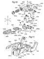
- Fig. 9 shows a further variation of embodiment of the toe-piece according to the present invention which, in this configuration, has opposition springs 1210 arranged parallel to the longitudinal direction X-X; as shown the springs 1210 are supported by associated means 1220 which are fixed to the base piece 110 and conventional per se and therefore not described in detail, the springs acting in this case against the head part 312 of the lever 311 and the operating principle of the toe-piece remaining the same as that already described.
- a further embodiment of the toe-piece according to the present invention comprises essentially:
- the sliding piece 2350 is made in the form of a box open laterally so as to allow seating of the cam 2311 and a constraining element 2600.
- Said element 2600 has a hole 2605 extending in the transverse direction Y-Y and suitable for engagement with a pin 2430a passing through corresponding holes 2113 in the sides 2111 of the fixed base 2100; in this way the element 2600 forms the means for constraining the sliding piece 2350 to the fixed base 2100 with respect to which the said sliding piece is able to be displaced in both directions and the support surface for the cam 2311.
- the constraining element is in the form of a "U" with arms 2601 which have two transverse coaxial holes, one of which 2602a is a through-hole and the other one 2602b threaded, suitable for engagement with a corresponding pin 2603 having a threaded end and therefore able to exert a compressive force on the arms 2601 of the "U" for the purposes which will be described below with reference to operation of the binding.
- the transverse arm 2604 of the "U” has, projecting axially therefrom, a pin 2605 able to form the support of resilient opposition means acting in the longitudinal direction X-X and consisting of a spring 2210 housed inside the sliding piece 2350 inside which it is inserted via a threaded hole 2351 which is closed by an adjusting screw 2351a, greater or lesser screwing of which causes greater/lesser compression of the spring and therefore greater/lesser resistance to release of the jaws 123.
- the sliding piece 2350 has a surface 2350a which is suitably shaped so as to interact with a corresponding surface 2311a of the said cam 2311 so as to cause correct centring thereof in the rest condition.
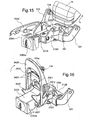
- the sliding piece 2350 has transverse extensions 2352 shaped in the manner of a cam 2352a in the vertical direction Z-Z and able to form a stop for the free end 2431a of arms 2431 of a lever 2430 for locking/releasing the sliding piece, able to be operated rotationally by the user about a pin 2430a inserted in the transverse direction y-y inside the said holes 2113 of the flanges 2111 of the base piece 2110.
- the toe-piece comprises, moreover, a front fork-shaped lever 2420 pivotably mounted on the base piece 2110 by means of an associated transverse pin 2420a inserted inside the holes 2114 of the flanges 2111 of the base 2110 and the rear ends of which 2420b are able to act on the corresponding resistance arm 123b of the jaw 123 so as to bring it from the rest (closed position) into a more open position able to allow insertion of the toe 1a of the ski boot.
- the operating principle of the toe-piece is as follows:
- the latter has an engaging seat 1420a inside which it is possible to insert the tip of the ski pole so as to exert the thrust providing the force for opening the toe-piece.
- the transverse screw 2603 it will be possible to adjust the transverse screw 2603, tightening the longitudinal arms 2601 of the U which, adhering more firmly to the surface of the cam 2311, takes up the play, resulting in restoration of the initial operating conditions.
- the toe-piece according to the invention allows easy adjustment depending on the variation in transverse width of the seats engaging with the ski boot, said width diminishing with the wear of the said seats, as well as a practical fitting action obtained by means of the thrusting force applied on the lever 2420 by the tip of the ski pole, resulting in widening of the jaws, allowing insertion of the toe of the ski boot.
Landscapes
- Footwear And Its Accessory, Manufacturing Method And Apparatuses (AREA)
- Fishing Rods (AREA)
- Surgical Instruments (AREA)
- Golf Clubs (AREA)
- Fittings On The Vehicle Exterior For Carrying Loads, And Devices For Holding Or Mounting Articles (AREA)
Claims (37)
- Pièce de pointe pour fixations de ski, comprenant une base de support fixe (100; 2100) comprenant deux mâchoires (123) situées l'une en face de l'autre et pourvues d'une broche respective (124) qui s'étend vers l'intérieur dans la direction transversale (Y-Y) et capable de s'engager avec un appui respectif (1b) dans la pointe (1a) d'une botte de ski, lesdites mâchoires (123) étant capables de tourner autour d'un axe (122) qui est sensiblement perpendiculaire à la base de support (100; 2100) d'une position fermée à une position ouverte, et vice versa, afin de verrouiller/libérer la pointe (1a) d'une botte de ski, lesdites mâchoires comprenant un bras de résistance (123b) qui coopère avec des moyens de réaction (311; 2311) capables de tourner autour d'un axe (320; 2320) perpendiculaire à la base (100; 2100) contre l'action opposée de moyens élastiques (210; 1210; 2210) intégrés à ladite pièce de pointe, caractérisée en ce que lesdits moyens de réaction (311, 2311) sont contraints sur une pièce coulissante (350; 2350) qui peut être déplacée dans les deux sens dans la direction longitudinale (X-X) contre l'action de rappel de moyens élastiques (357; 2210), et en ce que la broche respective (124) est conique.
- Pièce de pointe selon la revendication 1,
caractérisée en ce que ladite base fixe (2100) comprend une première pièce de base sensiblement plate (2110) présentant des côtés longitudinaux saillants (2111) comportant deux trous respectifs (2113, 2114) coaxiaux l'un par rapport à l'autre et agencés à des hauteurs différentes à partir du plan dans la direction (Z-Z). - Pièce de pointe selon la revendication 2, caractérisée en ce que la base (2110) comprend, incorporée dans celle-ci, une contre-pièce de base (2120) pourvue de brides saillantes (121) en forme de C, dont les bras parallèles au plan de la base (2110) comportent des trous coaxiaux respectifs (121a) qui sont capables de recevoir une broche (122) qui forme un axe de rotation qui est perpendiculaire au plan de la base (2110).
- Pièce de pointe selon la revendication 3, caractérisée en ce que lesdites mâchoires (123) sont montés de façon pivotante sur ledit axe de rotation (122) perpendiculaire au plan de la base (2110).
- Pièce de pointe selon la revendication 3, caractérisée en ce que lesdites mâchoires (123) sont situées l'une en face de l'autre et sont symétriques par rapport à l'axe longitudinal (X-X) et comprennent un bras de commande (123a) qui est sensiblement perpendiculaire à la base (110; 2110) et qui est pourvu de ladite broche conique (124) qui s'étend parallèlement à ladite base, et un bras de résistance (123b) qui est sensiblement parallèle à la base (110; 2110).
- Pièce de pointe selon la revendication 1, caractérisée en ce que lesdits moyens de réaction comprennent une came (2311) qui est configurée de manière à comprendre deux appuis courbes (2312) symétriques par rapport à l'axe longitudinal (X-X) et ouverts vers l'extérieur de manière à permettre l'entrée et la sortie des bras de résistance (123b) des mâchoires (123), ainsi qu'un trou traversant (2315) qui peut permettre l'insertion de moyens (2320) perpendiculaires à la base (2100) et qui forment un axe de rotation de la came (2311).
- Pièce de pointe selon la revendication 1, caractérisée en ce que la pièce coulissante (2350) est constituée sous la forme d'une boîte ouverte latéralement de manière à pouvoir recevoir la came (2311), et un élément (2600) pour exécuter la contrainte sur la base (2100).
- Pièce de pointe selon la revendication 1, caractérisée en ce que ladite pièce coulissante (2350) présente sur sa surface avant, un trou fileté (2351) qui est fermé par une vis de réglage (2351a).
- Pièce de pointe selon la revendication 1, caractérisée en ce que lesdits moyens d'opposition élastiques qui agissent dans la direction longitudinale X-X sont logés à l'intérieur de ladite pièce coulissante.
- Pièce de pointe selon la revendication 9, caractérisée en ce que lesdits moyens d'opposition élastiques comprennent un ressort (2210) qui est situé de façon longitudinale entre ladite vis de réglage (2351a) et une broche (2605) qui fait saillie axialement à partir desdits moyens de contrainte (2600).
- Pièce de pointe selon la revendication 1, caractérisée en ce que ladite pièce coulissante (2350) présente à son extrémité arrière une surface (2350a) qui est configurée de façon appropriée pour interagir avec une surface correspondante (2311a) de ladite came (2311) de manière à entraîner un centrage correct de celle-ci.
- Pièce de pointe selon la revendication 1, caractérisée en ce que la pièce coulissante (2350) présente à son extrémité avant des extensions transversales (2352) qui sont configurées comme une came (2352a) dans la direction verticale (Z-Z) et qui sont capables de former un arrêt pour l'extrémité libre (2431a) de bras (2431) d'un levier (2430) pour verrouiller/déverrouiller la pièce coulissante.
- Pièce de pointe selon la revendication 12, caractérisée en ce que ledit levier de verrouillage/déverrouillage (2430) est capable de tourner autour d'une broche (2430a) qui est insérée dans la direction transversale (Y-Y) de trous (2113) dans les brides (2111) de la pièce de base (2110).
- Pièce de pointe selon la revendication 7, caractérisée en ce que ledit élément pour contraindre la pièce coulissante (2350) sur la base (2110) se présente sous la forme d'un U comprenant des branches (2601) qui s'étendent dans la direction longitudinale (X-X) et qui comportent des trous coaxiaux longitudinaux, un (2602a) de ceux-ci étant un trou traversant, et l'autre (2602b) étant un trou fileté approprié pour s'engager avec une broche correspondante (2603) qui possède une extrémité filetée.
- Pièce de pointe selon la revendication 1, caractérisée en ce qu'elle comprend un levier avant (2420) qui se présente sous la forme d'une fourche qui est montée de façon pivotante sur la pièce de base (2110) au moyen d'une broche transversale associée (2420a) qui est insérée dans les trous (2114) dans les brides (2111) de la base (2110), les extrémités arrières (2420b) dudit levier étant capables d'agir sur le bras de résistance correspondant (123b) de la mâchoire (123) de manière à amener celui-ci de la position de repos dans une position plus ouverte où il peut permettre l'insertion de la pointe (1a) de la botte de ski.
- Pièce de pointe selon la revendication 1, caractérisée en ce que ladite base (100) comprend une première pièce de base (110) qui est associée à une contre-pièce de base (120) pourvue de brides (121) capables de recevoir une broche (122) qui forme un axe de rotation perpendiculaire au plan de la base (110) pour lesdites mâchoires (123).
- Pièce de pointe selon la revendication 16, caractérisée en ce que lesdites brides (121) sont saillantes en forme de C, et les bras parallèles au plan de la base (110) comportent les trous coaxiaux respectifs (121a) destinés à recevoir ladite broche (122).
- Pièce de pointe selon la revendication 16, caractérisée en ce que ladite pièce de base (110) présente des côtés longitudinaux saillants (111) qui sont perpendiculaires à ladite base et qui comportent un oeillet respectif (112) qui s'étend dans la direction longitudinale (X-X).
- Pièce de pointe selon la revendication 16, caractérisée en ce que ladite première pièce de base (110) comprend une bande (114) allongée dans la direction longitudinale vers l'avant et qui comporte un trou (114a) qui est capable de s'engager avec une broche de verrouillage correspondante (354a) dans la direction verticale (z-z) .
- Pièce de pointe selon la revendication 1, caractérisée en ce que lesdits moyens pour actionner les mâchoires (123) comprennent un levier (310) qui est formé par un corps central (311a) qui s'étend dans la direction longitudinale, et par une tête (311) qui est configurée de manière à présenter deux appuis courbes (312) qui sont symétriques par rapport à l'axe longitudinal (X-X) et qui s'ouvrent vers l'extérieur.
- Pièce de pointe selon la revendication 20, caractérisée en ce que ledit levier (311) comporte un trou traversant (315) qui peut permettre l'insertion de moyens (320) perpendiculaires à la base (100) et qui forment un axe de rotation du levier (310).
- Pièce de pointe selon la revendication 21, caractérisée en ce que ledit axe de rotation (320) consiste essentiellement en une broche filetée (321), dont la tête (321a) vient au contact contre la surface inférieure de la base (110), et dont la tige (321b) passe à travers un oeillet (115) dans ladite base et un oeillet (125) dans la contre-pièce de base (120) et entre dans ledit trou (315) du levier (310) de manière à s'engager avec une contre-broche (322) qui présente un filet femelle.
- Pièce de pointe selon la revendication 1, caractérisée en ce que ladite pièce coulissante (350) présente, à son extrémité avant, un oeillet (354) qui est destiné à recevoir des moyens de retenue (354a) qui sont capables d'empêcher la montée de la pièce coulissante dans la direction verticale (Z-Z) et de permettre le déplacement de celle-ci dans les deux sens dans la direction longitudinale (X-X).
- Pièce de pointe selon la revendication 1, caractérisée en ce que ladite pièce coulissante (350) comprend une bride (356) qui se présente sous la forme d'un L retourné dont la branche libre est capable de supporter des moyens de sécurité élastiques (357) qui agissent dans la direction longitudinale (X-X) contre l'action desdits moyens de commande (420).
- Pièce de pointe selon la revendication 1, caractérisée en ce que, à son extrémité avant, ladite pièce coulissante (350) présente un appui transversal (355) qui est capable de s'engager avec lesdits moyens de commande (410, 420).
- Pièce de pointe selon la revendication 1, caractérisée en ce que ladite pièce coulissante (350) est située, dans la direction verticale, entre deux bandes (340) d'une matière qui présente un coefficient de friction faible.
- Pièce de pointe selon la revendication 1, caractérisée en ce que lesdits moyens élastiques (200) comprennent une paire de ressorts (210) qui s'étendent dans la direction transversale et qui sont situés l'un en face de l'autre, l'extrémité libre de ceux-ci agissant sur les côtés des moyens (300) pour actionner les mâchoires (123).
- Pièce de pointe selon la revendication 27, caractérisée en ce que lesdits moyens élastiques (210) sont supportés par des éléments de guidage et de retenue transversaux respectifs (220) qui sont intégrés aux côtés (111) de la base (110).
- Pièce de pointe selon la revendication 28, caractérisée en ce que lesdits moyens (220) qui supportent les ressorts (210) peuvent être déplacés dans la direction longitudinale à l'intérieur desdits oeillets (112) des côtés saillants (111) de manière à modifier le point d'application de l'action d'opposition transversale des ressorts.
- Pièce de pointe selon la revendication 1, caractérisée en ce que lesdits moyens élastiques (1200) comprennent une paire de ressorts (1210) qui sont agencés parallèlement à la direction longitudinale (X-X) sur des côtés opposés du levier (311) et qui agissent contre la partie de tête (312) dudit levier.
- Pièce de pointe selon la revendication 30, caractérisée en ce que lesdits ressorts (1210) sont supportés par des moyens associés (1220) qui sont fixés à la pièce de base (110).
- Pièce de pointe selon la revendication 1, caractérisée en ce que lesdits moyens de commande (410, 420; 1410) comprennent un élément élastique (410) qui se présente sous la forme d'un U, dont les branches longitudinales (412) présentent des extrémités (412a) qui sont pliées vers l'extérieur pour être insérées dans des appuis correspondants (421; 1421) d'un levier (420; 1420) pour actionner l'ensemble de la pièce de pointe, qui peut être actionné de façon rotative par l'utilisateur.
- Pièce de pointe selon la revendication 32, caractérisée en ce que le bras transversal (411) dudit élément élastique est approprié pour être inséré à l'intérieur d'un appui transversal avant (355) de la pièce coulissante (350).
- Pièce de pointe selon la revendication 1, caractérisée en ce que ledit levier de commande (420) comporte un oeillet (422) qui est allongé dans la direction longitudinale et qui est capable de former un appui pour un bouton (430) qui peut être déplacé dans les deux sens de la direction longitudinale à l'intérieur dudit oeillet de manière à entraîner le verrouillage/ déverrouillage du mouvement de rotation du levier (310) qui actionne les mâchoires (123).
- Pièce de pointe selon la revendication 1, caractérisée en ce que ledit bouton (430) comprend une tête de saisie (431) et un corps en forme de fourche (432) qui peuvent être agencés sur une extension longitudinale (313) de celui-ci.
- Pièce de pointe selon la revendication 1, caractérisée en ce que le levier (420; 1420; 2420) comprend au moins un appui respectif (420a; 1420a; 2420a) destiné à s'engager avec la pointe d'un bâton de ski.
- Pièce de pointe selon la revendication 1, caractérisée en ce que la rotation vers l'extérieur desdites mâchoires (123) peut s'étendre à travers un angle qui est supérieur à 90°.
Applications Claiming Priority (2)
| Application Number | Priority Date | Filing Date | Title |
|---|---|---|---|
| IT001429A ITMI20051429A1 (it) | 2005-07-22 | 2005-07-22 | Puntale per attacchi da sci |
| PCT/IB2006/002131 WO2007010392A2 (fr) | 2005-07-22 | 2006-07-20 | Piece de pointe pour fixations de ski |
Publications (2)
| Publication Number | Publication Date |
|---|---|
| EP1907078A2 EP1907078A2 (fr) | 2008-04-09 |
| EP1907078B1 true EP1907078B1 (fr) | 2009-10-07 |
Family
ID=37589182
Family Applications (1)
| Application Number | Title | Priority Date | Filing Date |
|---|---|---|---|
| EP06779929A Not-in-force EP1907078B1 (fr) | 2005-07-22 | 2006-07-20 | Piece de pointe pour fixations de ski |
Country Status (5)
| Country | Link |
|---|---|
| EP (1) | EP1907078B1 (fr) |
| AT (1) | ATE444788T1 (fr) |
| DE (1) | DE602006009660D1 (fr) |
| IT (1) | ITMI20051429A1 (fr) |
| WO (1) | WO2007010392A2 (fr) |
Cited By (1)
| Publication number | Priority date | Publication date | Assignee | Title |
|---|---|---|---|---|
| DE202024101399U1 (de) | 2023-03-24 | 2024-05-13 | Cameron Allan Shute | Skibindungszehenstück |
Families Citing this family (28)
| Publication number | Priority date | Publication date | Assignee | Title |
|---|---|---|---|---|
| EP2300111B1 (fr) * | 2008-04-03 | 2018-01-31 | G3 Genuine Guide Gear Inc. | Fixation de pointe de chaussure de randonnée alpine |
| ATE526840T1 (de) | 2009-04-08 | 2011-10-15 | Ski Trab S R L | Skistiefel mit mitteln zur betätigung von entsprechenden halteelementen von tourenskibindungen |
| IT1396278B1 (it) * | 2009-04-15 | 2012-11-16 | Rigat | Puntale di un attacco da sci |
| IT1396339B1 (it) * | 2009-10-06 | 2012-11-16 | Roberto Giordani | Puntale di attacchi da sci alpinismo a bloccaggio perfezionato |
| EP2319595B1 (fr) * | 2009-11-04 | 2014-08-13 | Salewa Sport AG | Fixation de ski de fond dotée d'une plaque de base comprenant un agencement de trou de fixation et plaque de base |
| IT1397694B1 (it) * | 2010-01-22 | 2013-01-24 | Atk Race Srl | Puntale per attacchi da sci-alpinismo. |
| DE102010001603A1 (de) * | 2010-02-04 | 2011-08-04 | Salewa Sport Ag | Tourenskibindung mit Verriegelungsmechanismus |
| ITTO20110075A1 (it) * | 2011-01-31 | 2012-08-01 | Marco Rigat | Puntale di sicurezza per attacco da sci alpinismo. |
| DE102010043879A1 (de) * | 2010-11-12 | 2012-05-16 | Salewa Sport Ag | Tourenbindung mit Auslösemechanismus und Verriegelungsmechanismus |
| FR2972642B1 (fr) * | 2011-03-18 | 2017-03-17 | Felisaz Sas Fixations Plum | Lame ressort- selecteur de position verrouillee/deverrouillee pour fixation de ski-alpinisme |
| CH705579A2 (de) | 2011-09-29 | 2013-04-15 | Fritschi Ag Swiss Bindings | Frontautomat. |
| DE202011109616U1 (de) * | 2011-12-28 | 2012-02-06 | Sepp Heumann | Sicherheitsbindungssystem |
| DE102012207959B4 (de) * | 2012-05-11 | 2020-11-12 | Fritz Barthel | Vordereinheit einer Gleitbrettbindung und Gleitbrettbindung |
| FR2991592B1 (fr) * | 2012-06-12 | 2016-08-26 | Rossignol Sa | Butee a declenchement automatique en torsion |
| FR3002460B1 (fr) * | 2013-02-22 | 2017-08-25 | Rossignol Sa | Butee a declenchement automatique en torsion |
| DE102013003839A1 (de) * | 2013-03-07 | 2014-09-11 | Reinhold Zoor | Pin-Vorderbacken mit horizontalgelagerten Auslösebacken |
| DE102013204060B4 (de) * | 2013-03-08 | 2015-01-22 | Micado Cad-Solutions Gmbh | Vorderbacken für eine Skitourenbindung |
| EP2946817B1 (fr) * | 2014-05-19 | 2017-05-03 | Ski Trab S.r.l. | Pièce pour doigts de pied destinée à des fixations de randonnée |
| ITUB20153027A1 (it) | 2015-08-10 | 2017-02-10 | Scarpa Calzaturificio Spa | Scarpone da sci |
| FR3046083B1 (fr) * | 2015-12-23 | 2018-01-12 | Salomon Sas | Fixation de ski |
| EP3266504A1 (fr) * | 2016-07-07 | 2018-01-10 | Fritschi AG - Swiss Bindings | Fixation de ski |
| FR3072884B1 (fr) * | 2017-11-02 | 2022-01-21 | Rossignol Sa | Butee de dispositif de fixation d'une chaussure |
| SK8337Y1 (sk) | 2018-02-20 | 2019-01-08 | Gaborik Jozef | Predný diel viazania na lyže |
| IT201800009744A1 (it) | 2018-10-24 | 2020-04-24 | Atk Race Srl | Puntale di attacco da sci |
| FR3097773B1 (fr) | 2019-06-26 | 2022-01-21 | Rossignol Sa | Butée avant de fixation pour ski de randonnée |
| IT201900013143A1 (it) * | 2019-07-29 | 2021-01-29 | Atk Sports S R L | Puntale di attacco da sci per sci alpinismo |
| DE102021101355A1 (de) * | 2021-01-22 | 2022-07-28 | Salewa Sport Ag | Gleitbrettbindung mit in horizontaler richtung veschraubtem gehäuse |
| IT202100012872A1 (it) * | 2021-05-19 | 2022-11-19 | Atk Sports S R L | Porzione posteriore di attacco da sci alpinismo |
Family Cites Families (2)
| Publication number | Priority date | Publication date | Assignee | Title |
|---|---|---|---|---|
| US4348036A (en) * | 1980-08-19 | 1982-09-07 | Settembre Richard J | Safety binding for nordic skis |
| AT381458B (de) * | 1985-03-25 | 1986-10-27 | Barthel Fritz | Tourenskibindung |
-
2005
- 2005-07-22 IT IT001429A patent/ITMI20051429A1/it unknown
-
2006
- 2006-07-20 EP EP06779929A patent/EP1907078B1/fr not_active Not-in-force
- 2006-07-20 AT AT06779929T patent/ATE444788T1/de active
- 2006-07-20 DE DE602006009660T patent/DE602006009660D1/de active Active
- 2006-07-20 WO PCT/IB2006/002131 patent/WO2007010392A2/fr not_active Ceased
Cited By (1)
| Publication number | Priority date | Publication date | Assignee | Title |
|---|---|---|---|---|
| DE202024101399U1 (de) | 2023-03-24 | 2024-05-13 | Cameron Allan Shute | Skibindungszehenstück |
Also Published As
| Publication number | Publication date |
|---|---|
| EP1907078A2 (fr) | 2008-04-09 |
| ITMI20051429A1 (it) | 2007-01-23 |
| DE602006009660D1 (de) | 2009-11-19 |
| ATE444788T1 (de) | 2009-10-15 |
| WO2007010392A3 (fr) | 2007-04-05 |
| WO2007010392A2 (fr) | 2007-01-25 |
Similar Documents
| Publication | Publication Date | Title |
|---|---|---|
| EP1907078B1 (fr) | Piece de pointe pour fixations de ski | |
| EP2281614B1 (fr) | Talonnière comprenant une fourche à deux bras pour accrochage avec des chevilles sur la chaussure | |
| EP3300778B1 (fr) | Unité d'orteil pour fixation de randonnée en montagne | |
| US20130181427A1 (en) | Touring heel binding having a dynamic sliding region | |
| US10010782B2 (en) | Heel-piece for binding a boot on a gliding board | |
| US9440137B2 (en) | Toe-piece for ski-touring bindings | |
| EP2707110B1 (fr) | Dispositif de fixation de ski pour fixer une chaussure de ski sur un ski de descente ou analogue | |
| EP2243388B1 (fr) | Chaussure de ski avec des moyens pour actionner des éléments d'engagement correspondants de fixations de ski de randonnée | |
| US4421341A (en) | Safety ski binding | |
| WO2009153615A1 (fr) | Pièce de talon multi-position pour attaches de fixation de ski | |
| US7909352B2 (en) | Article including a button which is movable between at least two positions | |
| WO1980001141A1 (fr) | Fixation de ski a enclenchement par appui du pied | |
| US6390494B2 (en) | Cross-country ski binding | |
| US20040056449A1 (en) | Binding device with front unfastening | |
| US5265901A (en) | Heel unit for ski bindings with automatic reset means | |
| JPS5852666B2 (ja) | クロスカントリ用スキ−バインデイング | |
| EP2707111B1 (fr) | Dispositif de fixation de ski pour fixer une chaussure de ski sur un ski de descente ou analogue | |
| EP0448009B1 (fr) | Fixation de sécurité de ski | |
| US4607859A (en) | Safety ski binding | |
| US11524220B2 (en) | Ski binding | |
| US6412808B1 (en) | Boot/ski safety binding | |
| EP1602296B1 (fr) | Dispositif encliquetable en particulier pour chaussures de sport | |
| US20240325864A1 (en) | Ski Binding Heel Unit | |
| US4624475A (en) | Release ski binding | |
| US4573701A (en) | Release ski binding |
Legal Events
| Date | Code | Title | Description |
|---|---|---|---|
| PUAI | Public reference made under article 153(3) epc to a published international application that has entered the european phase |
Free format text: ORIGINAL CODE: 0009012 |
|
| AK | Designated contracting states |
Kind code of ref document: A2 Designated state(s): AT CH DE FR IT LI |
|
| 17P | Request for examination filed |
Effective date: 20080109 |
|
| RBV | Designated contracting states (corrected) |
Designated state(s): AT CH DE FR IT LI |
|
| GRAP | Despatch of communication of intention to grant a patent |
Free format text: ORIGINAL CODE: EPIDOSNIGR1 |
|
| DAX | Request for extension of the european patent (deleted) | ||
| GRAS | Grant fee paid |
Free format text: ORIGINAL CODE: EPIDOSNIGR3 |
|
| GRAA | (expected) grant |
Free format text: ORIGINAL CODE: 0009210 |
|
| AK | Designated contracting states |
Kind code of ref document: B1 Designated state(s): AT CH DE FR IT LI |
|
| REG | Reference to a national code |
Ref country code: CH Ref legal event code: EP |
|
| REF | Corresponds to: |
Ref document number: 602006009660 Country of ref document: DE Date of ref document: 20091119 Kind code of ref document: P |
|
| REG | Reference to a national code |
Ref country code: CH Ref legal event code: NV Representative=s name: DR. LUSUARDI AG |
|
| PLBE | No opposition filed within time limit |
Free format text: ORIGINAL CODE: 0009261 |
|
| STAA | Information on the status of an ep patent application or granted ep patent |
Free format text: STATUS: NO OPPOSITION FILED WITHIN TIME LIMIT |
|
| 26N | No opposition filed |
Effective date: 20100708 |
|
| PG25 | Lapsed in a contracting state [announced via postgrant information from national office to epo] |
Ref country code: IT Free format text: LAPSE BECAUSE OF FAILURE TO SUBMIT A TRANSLATION OF THE DESCRIPTION OR TO PAY THE FEE WITHIN THE PRESCRIBED TIME-LIMIT Effective date: 20091007 |
|
| REG | Reference to a national code |
Ref country code: FR Ref legal event code: PLFP Year of fee payment: 11 |
|
| PGFP | Annual fee paid to national office [announced via postgrant information from national office to epo] |
Ref country code: CH Payment date: 20160714 Year of fee payment: 11 |
|
| PGFP | Annual fee paid to national office [announced via postgrant information from national office to epo] |
Ref country code: DE Payment date: 20160929 Year of fee payment: 11 |
|
| REG | Reference to a national code |
Ref country code: FR Ref legal event code: PLFP Year of fee payment: 12 |
|
| REG | Reference to a national code |
Ref country code: DE Ref legal event code: R082 Ref document number: 602006009660 Country of ref document: DE |
|
| REG | Reference to a national code |
Ref country code: DE Ref legal event code: R119 Ref document number: 602006009660 Country of ref document: DE |
|
| REG | Reference to a national code |
Ref country code: CH Ref legal event code: PL |
|
| PG25 | Lapsed in a contracting state [announced via postgrant information from national office to epo] |
Ref country code: DE Free format text: LAPSE BECAUSE OF NON-PAYMENT OF DUE FEES Effective date: 20180201 Ref country code: CH Free format text: LAPSE BECAUSE OF NON-PAYMENT OF DUE FEES Effective date: 20170731 Ref country code: LI Free format text: LAPSE BECAUSE OF NON-PAYMENT OF DUE FEES Effective date: 20170731 |
|
| REG | Reference to a national code |
Ref country code: FR Ref legal event code: PLFP Year of fee payment: 13 |
|
| PGFP | Annual fee paid to national office [announced via postgrant information from national office to epo] |
Ref country code: FR Payment date: 20190725 Year of fee payment: 14 |
|
| PGFP | Annual fee paid to national office [announced via postgrant information from national office to epo] |
Ref country code: AT Payment date: 20190718 Year of fee payment: 14 |
|
| REG | Reference to a national code |
Ref country code: AT Ref legal event code: MM01 Ref document number: 444788 Country of ref document: AT Kind code of ref document: T Effective date: 20200720 |
|
| PG25 | Lapsed in a contracting state [announced via postgrant information from national office to epo] |
Ref country code: FR Free format text: LAPSE BECAUSE OF NON-PAYMENT OF DUE FEES Effective date: 20200731 |
|
| PG25 | Lapsed in a contracting state [announced via postgrant information from national office to epo] |
Ref country code: AT Free format text: LAPSE BECAUSE OF NON-PAYMENT OF DUE FEES Effective date: 20200720 |