EP1907308B2 - Drahtführender mantel - Google Patents
Drahtführender mantel Download PDFInfo
- Publication number
- EP1907308B2 EP1907308B2 EP06794491.8A EP06794491A EP1907308B2 EP 1907308 B2 EP1907308 B2 EP 1907308B2 EP 06794491 A EP06794491 A EP 06794491A EP 1907308 B2 EP1907308 B2 EP 1907308B2
- Authority
- EP
- European Patent Office
- Prior art keywords
- guidance
- wire
- support
- type
- supports
- Prior art date
- Legal status (The legal status is an assumption and is not a legal conclusion. Google has not performed a legal analysis and makes no representation as to the accuracy of the status listed.)
- Active
Links
Images


Classifications
-
- B—PERFORMING OPERATIONS; TRANSPORTING
- B65—CONVEYING; PACKING; STORING; HANDLING THIN OR FILAMENTARY MATERIAL
- B65H—HANDLING THIN OR FILAMENTARY MATERIAL, e.g. SHEETS, WEBS, CABLES
- B65H57/00—Guides for filamentary materials; Supports therefor
- B65H57/12—Tubes
-
- B—PERFORMING OPERATIONS; TRANSPORTING
- B23—MACHINE TOOLS; METAL-WORKING NOT OTHERWISE PROVIDED FOR
- B23K—SOLDERING OR UNSOLDERING; WELDING; CLADDING OR PLATING BY SOLDERING OR WELDING; CUTTING BY APPLYING HEAT LOCALLY, e.g. FLAME CUTTING; WORKING BY LASER BEAM
- B23K9/00—Arc welding or cutting
- B23K9/12—Automatic feeding or moving of electrodes or work for spot or seam welding or cutting
- B23K9/133—Means for feeding electrodes, e.g. drums, rolls, motors
- B23K9/1336—Driving means
-
- B—PERFORMING OPERATIONS; TRANSPORTING
- B65—CONVEYING; PACKING; STORING; HANDLING THIN OR FILAMENTARY MATERIAL
- B65H—HANDLING THIN OR FILAMENTARY MATERIAL, e.g. SHEETS, WEBS, CABLES
- B65H57/00—Guides for filamentary materials; Supports therefor
- B65H57/14—Pulleys, rollers, or rotary bars
Definitions
- the present invention relates to the technical field relating to the supply or transport of a wire, of any kind and section, from a place of packaging to a place of use.
- the object of the invention is more specifically a new sheath inside which moves the wire to be conveyed between the place of packaging and the place of use.
- the object of the invention finds a preferred application in the transport of a welding wire by the need for mobility at the welding zone and the need for protection against external aggression (dust, dirt).
- An additional constraint is related to the fact that the length of the sheath must be relatively small to overcome the wear problems, so that such a constraint limits the design possibilities of the machine incorporating such a sheath.
- patent US 1,898,060 discloses a welding machine incorporating two roller systems mounted perpendicular to each other to straighten the solder wire before use. This patent does not solve the problem of guiding a welding wire between its place of packaging and its place of use.
- the present invention therefore aims to overcome the disadvantages mentioned above by providing a sheath for guiding a wire, adapted to reduce the friction of the wire inside the sheath, even when it is bent in different directions. .
- the object of the invention is also to provide a sheath for guiding a wire, adapted to be of simple design, while ensuring its guiding function of the wire.
- the sheath according to the invention is in accordance with claim 1.
- first and second hinge means are made by a hinge of the same type, such as pivot, ball or elastic.
- At least one of the axes of a rolling member of the second guide assemblies extends in a direction perpendicular to that of at least one axis of a rolling member of the first sets of guiding and in that the first and second hinge means have hinge directions at least perpendicular to each other.
- the axes of the rolling members, forming part of the same guide assembly are parallel to each other.
- the first type of supports of the first guide assemblies are identical to the supports of the second type of the second guide assemblies.
- each support of the guide assemblies is equipped with a guide tube for the wire extending between the guide assembly carried by said support and the guide assembly carried by the upstream or downstream support.
- the guide sheath according to the invention preferably comprises stop means for limiting the articulation amplitude of the first and second articulation means.
- the latter comprises a protective envelope in which are mounted the supports of the first and second guide assemblies.
- the protective envelope incorporates a spring.
- Another object of the invention is to propose a system for feeding a wire by means of drive means, comprising a guide sheath according to the invention disposed between the wire storage location and the place. use of the wire.
- the object of the invention relates to a sheath 1 guiding a wire 2 moving inside the sheath in a guide path 3 , in a direction of movement represented by the arrow F 1 .
- the sheath 1 according to the invention is used with at least one advance system 4 for conveying the wire 2 from a storage or conditioning station 5 1 , 5 2 or 5 3 to a utilization station 6 .
- the feed system 4 comprises drive means 7 of the wire of any type known per se, such as pushed, pulled, pushed-pulled or push-pushed type.
- the drive means 7 will not be described more precisely because they are not part of the object of the invention and are well known to those skilled in the art.
- the wire 2 is solid or hollow and has a section for example circular or other.
- the wire 2 is packaged in different forms, such as in a drum 1 , crown, barrel 5 2 or coil 5 3 , as illustrated in FIG. Fig. 1 .
- the wire 2 is a welding wire guided inside the sheath 1 according to the invention, in order to be conveyed to a utilization station 6 , such as a welding station associated with a robot 8 .
- the sheath 1 according to the invention can thus be used between the welding station 6 and the feed system 4 near which is placed in the illustrated example, the coil 5 3 , or between the welding station 6 and a packaging deported such a barrel 5 2 or a drum 5 1 for example.
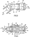
- the Fig. 2 to 4 illustrate a first embodiment of a sheath 1 according to the invention comprising a series of supports of the first type 1 for a first guide assembly 11 1 for the wire 2 and a series of second type supports 2 for 2 second guide assemblies 11 2 for the wire.
- the supports of the first type 10 1 and the supports of the second type 10 2 are arranged successively and alternately, so that outside the supports forming the two ends of the sheath, a support of a given type is interposed between two supports of a different type.
- a support of a given type is adjacent or adjacent, on one of its sides, a support of a different type, said upstream, in consideration of the direction of advancement wire and, according to its opposite side, a different support, said downstream.
- each support of a type 10 1 , 10 2 is articulated with each of the adjacent or adjacent supports of a different type.
- each support of a given type for example of the first type 1
- each support of a second type 2 2 is articulated on the one hand, with the aid of the first articulation means 15 with the first type of upstream support 10 1 according to at least one articulation direction A and, secondly, using second hinge means 17 with the first type of downstream support 10 1 according to at least one articulation direction B.
- the articulation means 15, 17 are adapted to allow a movement of the supports between them in at least two articulation directions A, B perpendicular to each other, so that the sheath can follow curvatures extending in planes. different.
- the articulation directions A and B are perpendicular to each other and to the direction of advance of the wire 2 .
- the supports of the first type 1 are identical to the supports of the second type 2 .
- the supports of the first type 1 are angularly offset, along the axis of the sheath, by 90 ° with respect to the supports of the second type 2 .
- the subscripts 1 and 2 of the various components of media will be attached, respectively, to the first media Type 10 1 and the second Type 10 2 supports.
- Each support 10 1 , 10 2 is in the form of a tubular or annular body 20 1 , 20 2 delimiting, internally, a cage 21 1 , 21 2 mounting for a guide assembly 11 1 , 11 2 .
- each guide assembly 11 1 , 11 2 comprises rolling members 23 1 , 23 2 , mounted facing each other in order to define the guide path 3 for the wire 2 .
- Each rolling member 23 1 , 23 2 is rotatably mounted along an axis 25 1 , 25 2 carried by the support 10 1 , 10 2 .
- each guide assembly 11 1 , 11 2 comprises two rolling members 23 1 , 23 2 carried by axes extending parallel to each other.
- Each rolling member 23 1 , 23 2 may be made by a roller or a roller, having a constant circular cross section, as shown in FIG. Fig. 4 , without groove or with a groove 26 , as illustrated in FIG. Fig. 5 or with a retaining lateral rib 27 , as illustrated in FIG. Fig. 6 .
- each guide assembly 11 1 , 11 2 may comprise a number of rolling members different from two, such as three members whose axes are shifted between them by 120 ° to form a guide path 3 of triangular section, as shown in Fig. 7 .
- the spacing of the rolling members 23 1 , 23 2 , placed vis-à-vis to form a guide assembly, is chosen so that the guide path 3 has a passage section greater than the diameter of the wire.
- This passage section is advantageously chosen to allow the passage of son of different diameters. It must be considered that the wire 2 can thus pass freely in the parts of the sheath that are rectilinear or straight, while the wire 2 is in contact with the rolling members located in the parts of the sheath undergoing a curvature.
- Each body 20 1 , 20 2 is advantageously extended, opposite the mounting cage 21 1 , 21 2 , by a guide tube 30 1 , 30 2 for the wire, thus delimiting the guide path 3 for the wire .
- Each guide tube 30 1 , 30 2 thus extends between the guide assembly 11 1 , 11 2 carried by said corresponding support and the guide assembly carried by the downstream support.
- each guide tube 30 1 , 2 ensures guiding continuity for the wire between two adjacent or consecutive guide assemblies 11 1 , 11 2 carried by two supports of different type.
- Each guide tube 30 1 , 2 preferably has a frustoconical longitudinal section which narrows towards the downstream support.
- Each body 20 1 , 20 2 is also provided with two arms 32 1 , 32 2 , extending parallel to each other and on either side of the guide tube 30 1 , 2 .
- the two arms 32 1 , 32 2 are each provided with a receiving orifice 33 1 , 33 2 for respectively a pivot 34 2 , 34 1 arranged on the bodies 20 1 , 20 2 .
- the two receiving orifices 33 1 of a support are aligned and are adapted to receive the two pivots 34 2 of a downstream support for forming the first articulation means 15 , while the two pivots 34 1 of said support with which cooperate the two orifices 33 2 of an upstream support form the second articulation means 17 .
- each joint A, B is located in the vicinity of a guide assembly 11 1 , 11 2 .
- each joint A, B adjacent to a guide assembly, extends substantially parallel to the axis of at least one rolling member belonging to said guide assembly.
- the articulation means 15 have, for example, a hinge direction A which is parallel and close to the axes 25 2 of the neighboring rolling members while the hinge means 17 have a hinge direction B which is parallel and close to the axes 25 1 , neighboring rolling members.
- the sheath 1 comprises stop means 40 adapted to limit the amplitude of the first 15 and second 17 articulation means.
- the limitation means 40 are formed by the guide tube 30 1 , 30 2 of a support adapted to abut on the body of a neighboring support.
- the misalignment between two consecutive media can be limited to a value of the order of 30 °.
- the sheath 1 makes it possible to guide the wire 2 during its advancement via, in particular, the rolling members 23 1 , 23 2 .
- the resistance to the advancement of the wire is due solely to the friction of the rolling member on its axis.
- the guiding of the wire 2 is thus ensured, even if the sheath undergoes displacements, in particular at its place of use, causing changes of curvature in different planes.
- the implementation of the hinge means 15, 17 in two different planes, alternated from one support to the other allows the sheath to follow different conformations.
- all the supports 10 1 , 10 2 can be mounted inside a protective envelope 50, as illustrated in FIG. Fig. 2 .
- This protective envelope 50 may possibly be associated with a spiral spring 51 which, in the example shown, is directly integrated with the protective envelope.
- a spring 51 gives the sheath, a determined stiffness also contributing to ensuring the alignment of the supports together.
- each pivot joint can be replaced by an elastic connection using one or more springs or elastic elements 55, as illustrated in FIG. Fig. 8 interposed between the supports 10 1 , 10 2 .
- each support body 20 1 , 20 2 thus has, on either side, a hemispherical portion 57 1 , 57 2 each cooperating with a complementary and opposite hemispherical portion 57 2 , 57 1 of FIG. a nearby support.
- Each support is thus assembled to each adjacent support, by a ball joint allowing a relative angular displacement of the supports in different directions.
- the supports 10 1 , 10 2 are mounted without mechanical connection to each other but being mounted inside a sheath 50 in which are mounted the supports cooperating with each other by conformations 60 1 , 60 2 , arranged on the supports and cooperating with each other to ensure articulation between two consecutive or neighboring supports.
Landscapes
- Engineering & Computer Science (AREA)
- Plasma & Fusion (AREA)
- Mechanical Engineering (AREA)
- Physics & Mathematics (AREA)
- Guides For Winding Or Rewinding, Or Guides For Filamentary Materials (AREA)
- Electric Cable Arrangement Between Relatively Moving Parts (AREA)
- Basic Packing Technique (AREA)
- Media Introduction/Drainage Providing Device (AREA)
- Endoscopes (AREA)
- Packaging Of Annular Or Rod-Shaped Articles, Wearing Apparel, Cassettes, Or The Like (AREA)
- Ultra Sonic Daignosis Equipment (AREA)
- Electrostatic Charge, Transfer And Separation In Electrography (AREA)
- Electrical Discharge Machining, Electrochemical Machining, And Combined Machining (AREA)
- Surgical Instruments (AREA)
- Paper (AREA)
Claims (7)
- Mantel zur Führung eines Drahtes (2), der sich in einer gegebenen Vorschubrichtung in einem innerhalb des Mantels ausgebildeten Führungskanal (3) bewegt, wobei der Mantel umfasst:• Träger eines ersten Typs (101) für erste Führungsanordnungen (111) für den Draht, die jeweils Rollorgane (231) umfassen, welche einander gegenüberliegend angeordnet sind, um zwischen ihnen einen Teil des Kanals zur Führung des Drahtes zu definieren, wobei jedes Rollorgan drehfrei um eine von einem Träger getragene Achse (251) angebracht ist,dadurch gekennzeichnet, dass er Träger eines zweiten Typs (102) für zweite Führungsanordnungen (112) für den Draht umfasst, die jeweils Rollorgane (232) umfassen, welche einerseits einander gegenüberliegend angeordnet sind, um zwischen ihnen einen Teil des Kanals zur Führung des Drahtes zu definieren, und andererseits jeweils drehfrei um eine von dem Träger getragene Achse (252) angeordnet sind, wobei wenigstens eine der Achsen eines Rollorgans der zweiten Führungsanordnungen in einer anderen Richtung als wenigstens eine Achse eines Rollorgans der ersten Führungsanordnungen verläuft, wobei die Träger der zweiten Führungsanordnungen mit den Trägern der ersten Führungsanordnungen abwechselnd angeordnet sind, und• für jeden Träger eines Typs, der von vorgeordneten und nachgeordneten Trägern eines anderen Typs eingerahmt ist, erste Anlenkmittel (15) entlang wenigstens einer Anlenkrichtung (A) zwischen einem Träger eines Typs und dem vorgeordneten Träger eines anderen Typs sowie zweite Anlenkmittel (17) zwischen dem Träger eines Typs und dem nachgeordneten Träger eines anderen Typs, entlang wenigstens einer von der Anlenkrichtung zwischen dem Träger und dem vorgeordneten Träger abweichenden Anlenkrichtung (B), wobei die ersten (15) und die zweiten (17) Anlenkmittel durch ein Gelenk gleicher Art, wie einem Drehgelenk, Kugelgelenk oder elastischen Gelenk realisiert sind,• wobei die Träger des ersten Typs (101) der ersten Führungsanordnungen (111) mit den Trägern (102) des zweiten Typs der zweiten Führungsanordnungen (112) identisch sind, wobei jeder Träger (101, 102) der Führungsanordnungen mit einem Führungsrohr (301, 302) für den Draht (2) ausgestattet ist, das sich zwischen der von dem Träger getragenen Führungsanordnung und der von dem vorgeordneten oder nachgeordneten Träger getragenen Führungsanordnung erstreckt.
- Führungsmantel nach Anspruch 1, dadurch gekennzeichnet, dass wenigstens eine der Achsen eines Rollorgans (231, 232) der zweiten Führungsanordnungen (112) sich in einer Richtung erstreckt, die zu der Richtung wenigstens einer Achse eines Rollorgans der ersten Führungsanordnungen (111) senkrecht verläuft, und dass die ersten (15) und zweiten (17) Anlenkmittel wenigstens senkrecht zueinander verlaufende Anlenkrichtungen aufweisen.
- Führungsmantel nach Anspruch 2, dadurch gekennzeichnet, dass die Achsen (251, 252) der Rollorgane, die zu einer gleichen Führungsanordnung gehören, parallel zueinander verlaufen.
- Führungsmantel nach einem der Ansprüche 1 bis 3, dadurch gekennzeichnet, dass er Anschlagmittel (40) umfasst, die ermöglichen, den Gelenkausschlag der ersten und der zweiten Anlenkmittel zu begrenzen.
- Führungsmantel nach einem der Ansprüche 1 bis 4, dadurch gekennzeichnet, dass er eine Schutzhülle (50) umfasst, in der die Träger (101, 102) der ersten und zweiten Führungsanordnungen angebracht sind.
- Führungsmantel nach Anspruch 5, dadurch gekennzeichnet, dass in die Schutzhülle (50) eine Feder (51) integriert ist.
- System für den Vorschub (4) eines Drahtes mit Hilfe von Antriebsmitteln (7), dadurch gekennzeichnet, dass es einen Führungsmantel (1) für den Draht (2) nach einem der Ansprüche 1 bis 6 umfasst, der zwischen dem Lagerungsort des Drahtes und dem Verwendungsort des Drahtes angeordnet ist.
Priority Applications (1)
| Application Number | Priority Date | Filing Date | Title |
|---|---|---|---|
| PL06794491T PL1907308T3 (pl) | 2005-07-22 | 2006-07-20 | Prowadnik drutu |
Applications Claiming Priority (2)
| Application Number | Priority Date | Filing Date | Title |
|---|---|---|---|
| FR0507810A FR2888825B1 (fr) | 2005-07-22 | 2005-07-22 | Gaine pour le guidage d'un fil |
| PCT/FR2006/050738 WO2007010171A2 (fr) | 2005-07-22 | 2006-07-20 | Gaine pour le guidage d'un fil |
Publications (3)
| Publication Number | Publication Date |
|---|---|
| EP1907308A2 EP1907308A2 (de) | 2008-04-09 |
| EP1907308B1 EP1907308B1 (de) | 2010-06-23 |
| EP1907308B2 true EP1907308B2 (de) | 2017-05-03 |
Family
ID=36145911
Family Applications (1)
| Application Number | Title | Priority Date | Filing Date |
|---|---|---|---|
| EP06794491.8A Active EP1907308B2 (de) | 2005-07-22 | 2006-07-20 | Drahtführender mantel |
Country Status (7)
| Country | Link |
|---|---|
| US (1) | US20090200284A1 (de) |
| EP (1) | EP1907308B2 (de) |
| AT (1) | ATE471906T2 (de) |
| DE (1) | DE602006015060D1 (de) |
| FR (1) | FR2888825B1 (de) |
| PL (1) | PL1907308T3 (de) |
| WO (1) | WO2007010171A2 (de) |
Families Citing this family (31)
| Publication number | Priority date | Publication date | Assignee | Title |
|---|---|---|---|---|
| DE102007015946A1 (de) * | 2007-03-27 | 2008-10-02 | Sidergas Spa | Flexible Führung für einen Schweißdraht |
| US8453960B2 (en) * | 2008-05-27 | 2013-06-04 | Awds Technologies Srl | Wire guiding system |
| EP2174741B1 (de) | 2008-10-07 | 2012-06-20 | SIDERGAS SpA | Abdeckung für einen Schweißdrahtbehälter |
| WO2011009468A1 (en) * | 2009-07-20 | 2011-01-27 | Awds Technologies Srl | A wire guiding liner, an particular a welding wire liner, with biasing means between articulated guiding bodies |
| US20110042355A1 (en) * | 2009-08-21 | 2011-02-24 | Carlo Gelmetti | Feeding system for a welding wire for a submerged welding process |
| US20110114617A1 (en) * | 2009-11-13 | 2011-05-19 | Carlo Gelmetti | Liner, in particular for welding wire |
| US8389901B1 (en) | 2010-05-27 | 2013-03-05 | Awds Technologies Srl | Welding wire guiding liner |
| US20120211479A1 (en) * | 2011-02-18 | 2012-08-23 | Illinois Tool Works Inc. | Self-cleaning welding wire conduit |
| WO2013009499A1 (en) * | 2011-07-08 | 2013-01-17 | Elco Enterprises, Inc. | Wire guide module with a housing and rollers method of guiding a wire and a wire dispensing system with such module |
| DE202011103453U1 (de) | 2011-07-18 | 2011-09-08 | Wilhelm Merkle | Schweißvorrichtung |
| DE202011103454U1 (de) | 2011-07-18 | 2011-09-28 | Wilhelm Merkle | Schweißvorrichtung |
| DE202011104120U1 (de) | 2011-08-05 | 2011-11-21 | Awds Technologies S.R.L. | Drahtführung, insbesondere zur Führung von Schweißdraht |
| US8882018B2 (en) | 2011-12-19 | 2014-11-11 | Sidergas Spa | Retainer for welding wire container and welding wire container with retainer |
| ITMI20121423A1 (it) * | 2012-08-09 | 2014-02-10 | Awds Technologies Srl | "guaina per guidare e trasportare del filo, in particolare filo per saldatura" |
| EP2695696B1 (de) | 2012-08-09 | 2017-03-15 | AWDS Technologies SRL | Leitung zum Führen eines Drahtes, insbesondere eines Schweißdrahtes, mit zwei unterschiedlichen Körpern |
| US9932782B2 (en) | 2013-01-09 | 2018-04-03 | C6 Technologies As | Well intervention cable bending restriction for a rigid resilient rod-shaped intervention cable |
| US10294065B2 (en) | 2013-06-06 | 2019-05-21 | Sidergas Spa | Retainer for a welding wire container and welding wire container |
| US10343231B2 (en) | 2014-05-28 | 2019-07-09 | Awds Technologies Srl | Wire feeding system |
| DE102014108208A1 (de) * | 2014-06-11 | 2015-12-17 | Friedrich-Alexander-Universität Erlangen-Nürnberg | Drahtführelement, Drahtwickelmaschine mit einem solchen, Verfahren zum Einbringen von Draht und Verfahren zum Zuführen von Draht |
| DE102014009390A1 (de) * | 2014-06-25 | 2015-12-31 | Fraunhofer-Gesellschaft zur Förderung der angewandten Forschung e.V. | Vorrichtung zur räumlich unterstützten Führung eines biegeelastischen Stranggutes sowie deren Verwendung in einer Anordnung zum Herstellen eines dreidimensionalen Objektes im Wege eines generativen Herstellverfahrens |
| US10010962B1 (en) | 2014-09-09 | 2018-07-03 | Awds Technologies Srl | Module and system for controlling and recording welding data, and welding wire feeder |
| US10350696B2 (en) | 2015-04-06 | 2019-07-16 | Awds Technologies Srl | Wire feed system and method of controlling feed of welding wire |
| US9975728B2 (en) | 2015-09-10 | 2018-05-22 | Sidergas Spa | Wire container lid, wire container and wire feeding system |
| MX378361B (es) * | 2015-11-06 | 2025-03-10 | Elco Entpr Inc | Sistema de guia de alambre flexible. |
| GB2558815A (en) | 2015-11-18 | 2018-07-18 | Halliburton Energy Services Inc | Segmented bend-limiter for slickline rope sockets and cable-heads |
| US9950857B1 (en) | 2016-10-17 | 2018-04-24 | Sidergas Spa | Welding wire container |
| US11278981B2 (en) | 2020-01-20 | 2022-03-22 | Awds Technologies Srl | Device for imparting a torsional force onto a wire |
| US11174121B2 (en) | 2020-01-20 | 2021-11-16 | Awds Technologies Srl | Device for imparting a torsional force onto a wire |
| EP4291520A1 (de) * | 2021-02-11 | 2023-12-20 | Elco Enterprises, Inc. | Drahtführungsmodul und system |
| KR102540380B1 (ko) * | 2021-10-15 | 2023-06-05 | 황지윤 | 회동각도의 조절이 가능한 라이너 송급시스템 |
| CN115352959B (zh) * | 2022-08-19 | 2024-05-14 | 北京华电瑞通电力工程技术有限公司 | 一种电力工程施工高效输送装置 |
Citations (9)
| Publication number | Priority date | Publication date | Assignee | Title |
|---|---|---|---|---|
| US1258233A (en) † | 1916-04-10 | 1918-03-05 | Clare P Mccaskey | Flexible shaft. |
| US1602691A (en) † | 1924-05-08 | 1926-10-12 | Alfred S Mccaskey | Flexible shaft |
| US2457910A (en) † | 1946-02-02 | 1949-01-04 | W L Maxson Corp | Flexible cable |
| US3274850A (en) † | 1964-11-04 | 1966-09-27 | Nazarene F Tascio | Flexible push-pull control cable |
| DE2525938A1 (de) † | 1975-06-11 | 1976-12-16 | Messer Griesheim Gmbh | Schweisseinrichtung zum schweissen, insbesondere up-schweissen, von innennaehten |
| JPH09191520A (ja) † | 1996-01-05 | 1997-07-22 | Hitachi Cable Ltd | ローラ付ケーブルガイド |
| US5994659A (en) † | 1996-06-20 | 1999-11-30 | General Electric Company | Method and apparatus for welding with preheated filler material |
| US6729606B1 (en) † | 1999-08-10 | 2004-05-04 | I.C.M. Group | Device for guiding at least a flexible elongated element such as a cable or the like, with substantially closed contour |
| WO2006091075A1 (en) † | 2005-01-17 | 2006-08-31 | Marcel Francesco De Keizer | Wire guide |
Family Cites Families (6)
| Publication number | Priority date | Publication date | Assignee | Title |
|---|---|---|---|---|
| US1898060A (en) * | 1919-09-11 | 1933-02-21 | Gen Electric | Method and apparatus for electric arc welding |
| DE449929C (de) * | 1924-08-09 | 1928-03-28 | Siemens Schuckertwerke Akt Ges | Lichtbogenschweissapparat |
| US2694130A (en) * | 1952-08-28 | 1954-11-09 | Posy A Howard | Arc welding wire guide |
| DE2222493A1 (de) * | 1972-05-08 | 1973-11-22 | Erich Geiger | Kugelumlenkung bei kugelumlaufmutter |
| US4278238A (en) * | 1980-01-21 | 1981-07-14 | Western Electric Company, Inc. | Cable feeding tool |
| US5215338A (en) * | 1985-04-09 | 1993-06-01 | Tsubakimoto Chain Co. | Flexible supporting sheath for cables and the like |
-
2005
- 2005-07-22 FR FR0507810A patent/FR2888825B1/fr not_active Expired - Lifetime
-
2006
- 2006-07-20 DE DE602006015060T patent/DE602006015060D1/de active Active
- 2006-07-20 EP EP06794491.8A patent/EP1907308B2/de active Active
- 2006-07-20 PL PL06794491T patent/PL1907308T3/pl unknown
- 2006-07-20 AT AT06794491T patent/ATE471906T2/de active
- 2006-07-20 WO PCT/FR2006/050738 patent/WO2007010171A2/fr not_active Ceased
- 2006-07-20 US US11/989,120 patent/US20090200284A1/en not_active Abandoned
Patent Citations (9)
| Publication number | Priority date | Publication date | Assignee | Title |
|---|---|---|---|---|
| US1258233A (en) † | 1916-04-10 | 1918-03-05 | Clare P Mccaskey | Flexible shaft. |
| US1602691A (en) † | 1924-05-08 | 1926-10-12 | Alfred S Mccaskey | Flexible shaft |
| US2457910A (en) † | 1946-02-02 | 1949-01-04 | W L Maxson Corp | Flexible cable |
| US3274850A (en) † | 1964-11-04 | 1966-09-27 | Nazarene F Tascio | Flexible push-pull control cable |
| DE2525938A1 (de) † | 1975-06-11 | 1976-12-16 | Messer Griesheim Gmbh | Schweisseinrichtung zum schweissen, insbesondere up-schweissen, von innennaehten |
| JPH09191520A (ja) † | 1996-01-05 | 1997-07-22 | Hitachi Cable Ltd | ローラ付ケーブルガイド |
| US5994659A (en) † | 1996-06-20 | 1999-11-30 | General Electric Company | Method and apparatus for welding with preheated filler material |
| US6729606B1 (en) † | 1999-08-10 | 2004-05-04 | I.C.M. Group | Device for guiding at least a flexible elongated element such as a cable or the like, with substantially closed contour |
| WO2006091075A1 (en) † | 2005-01-17 | 2006-08-31 | Marcel Francesco De Keizer | Wire guide |
Also Published As
| Publication number | Publication date |
|---|---|
| FR2888825A1 (fr) | 2007-01-26 |
| WO2007010171A3 (fr) | 2007-03-15 |
| ATE471906T2 (de) | 2010-07-15 |
| EP1907308B1 (de) | 2010-06-23 |
| DE602006015060D1 (de) | 2010-08-05 |
| PL1907308T3 (pl) | 2011-06-30 |
| US20090200284A1 (en) | 2009-08-13 |
| FR2888825B1 (fr) | 2007-10-19 |
| EP1907308A2 (de) | 2008-04-09 |
| WO2007010171A2 (fr) | 2007-01-25 |
Similar Documents
| Publication | Publication Date | Title |
|---|---|---|
| EP1907308B2 (de) | Drahtführender mantel | |
| EP2125301B1 (de) | Kompakter manipulationsroboter | |
| EP2184240B1 (de) | Vorrichtung zum Verschieben auf einem Endlosband mit anpassbarer Bewegungsbahn | |
| EP2007541A1 (de) | Orbitalträger mit mindestens zwei komponenten in form von kreissegmenten, die miteinander verbunden werden können, vorrichtung zum stumpfschweissen von rohren zur bildung einer solch einen orbitalträger umfassenden rohrleitung | |
| EP1854591B1 (de) | Parallelroboter | |
| EP2440481A1 (de) | Förderanlage mit mindestens einem gekrümmten gang | |
| EP2468631B1 (de) | Mit einem eigenen Motorantrieb ausgestattetes Gelenk, und automatisch regulierte Gelenkanordnung | |
| CA2760317A1 (en) | Automatic mechanical guide system for one or more welding unit torches with three pivot axes for the torch(es) | |
| FR2860756A1 (fr) | Dispositif de transfert sans contact d'energie electrique | |
| WO2018091814A1 (fr) | Machine et procédé pour la pose simultanée et en hélice de câbles sur la surface externe d'un élément unitaire de conduite de transport de fluides | |
| EP1973820B1 (de) | Pneumatischer förderer | |
| EP1409907A1 (de) | Wagen zum tragen von wekzeugen, insbesondere in einer kanalisation | |
| FR3015320A1 (fr) | Machine de soudure a arc electrique | |
| EP2331316A1 (de) | Verfahren und anlage zur herstellung einer lage aus bewehrungsstreifen | |
| FR2900139A1 (fr) | Station de support d'un convoyeur a bande et convoyeur la comportant | |
| EP3771503B1 (de) | Biegevorrichtung | |
| FR3044955A1 (de) | ||
| FR2743932A1 (fr) | Outil de gainage d'un faisceau de fils | |
| WO2018115787A1 (fr) | Methode et installation de reglage du pas des spires d'une carcasse metallique | |
| WO2014102029A1 (fr) | Ligne d'echappement de vehicule automobile comportant une rotule perfectionnee | |
| WO2015004398A2 (fr) | Roue de guidage pour les ensembles de pose de couches de fils d'armure | |
| FR3020000A1 (fr) | Connexion flottante pour outil | |
| WO2009004397A1 (fr) | Rouleau pour convoyeur a bande defilante agence pour provoquer spontanement un centrage de la bande sur son chemin de guidage | |
| FR3140574A1 (fr) | Machine d’application de fibres avec moyens d’acheminement de fibres particuliers | |
| EP1661779A1 (de) | Fahrzeugwaschanlage |
Legal Events
| Date | Code | Title | Description |
|---|---|---|---|
| PUAI | Public reference made under article 153(3) epc to a published international application that has entered the european phase |
Free format text: ORIGINAL CODE: 0009012 |
|
| 17P | Request for examination filed |
Effective date: 20080206 |
|
| AK | Designated contracting states |
Kind code of ref document: A2 Designated state(s): AT BE BG CH CY CZ DE DK EE ES FI FR GB GR HU IE IS IT LI LT LU LV MC NL PL PT RO SE SI SK TR |
|
| 17Q | First examination report despatched |
Effective date: 20080428 |
|
| GRAP | Despatch of communication of intention to grant a patent |
Free format text: ORIGINAL CODE: EPIDOSNIGR1 |
|
| GRAS | Grant fee paid |
Free format text: ORIGINAL CODE: EPIDOSNIGR3 |
|
| GRAA | (expected) grant |
Free format text: ORIGINAL CODE: 0009210 |
|
| AK | Designated contracting states |
Kind code of ref document: B1 Designated state(s): AT BE BG CH CY CZ DE DK EE ES FI FR GB GR HU IE IS IT LI LT LU LV MC NL PL PT RO SE SI SK TR |
|
| REG | Reference to a national code |
Ref country code: CH Ref legal event code: EP |
|
| REG | Reference to a national code |
Ref country code: IE Ref legal event code: FG4D Free format text: LANGUAGE OF EP DOCUMENT: FRENCH |
|
| REF | Corresponds to: |
Ref document number: 602006015060 Country of ref document: DE Date of ref document: 20100805 Kind code of ref document: P |
|
| REG | Reference to a national code |
Ref country code: SE Ref legal event code: TRGR |
|
| REG | Reference to a national code |
Ref country code: CH Ref legal event code: NV Representative=s name: BOVARD AG PATENTANWAELTE |
|
| REG | Reference to a national code |
Ref country code: NL Ref legal event code: T3 |
|
| PG25 | Lapsed in a contracting state [announced via postgrant information from national office to epo] |
Ref country code: LT Free format text: LAPSE BECAUSE OF FAILURE TO SUBMIT A TRANSLATION OF THE DESCRIPTION OR TO PAY THE FEE WITHIN THE PRESCRIBED TIME-LIMIT Effective date: 20100623 |
|
| PGFP | Annual fee paid to national office [announced via postgrant information from national office to epo] |
Ref country code: MC Payment date: 20100920 Year of fee payment: 5 |
|
| LTIE | Lt: invalidation of european patent or patent extension |
Effective date: 20100623 |
|
| PG25 | Lapsed in a contracting state [announced via postgrant information from national office to epo] |
Ref country code: SI Free format text: LAPSE BECAUSE OF FAILURE TO SUBMIT A TRANSLATION OF THE DESCRIPTION OR TO PAY THE FEE WITHIN THE PRESCRIBED TIME-LIMIT Effective date: 20100623 Ref country code: LV Free format text: LAPSE BECAUSE OF FAILURE TO SUBMIT A TRANSLATION OF THE DESCRIPTION OR TO PAY THE FEE WITHIN THE PRESCRIBED TIME-LIMIT Effective date: 20100623 Ref country code: FI Free format text: LAPSE BECAUSE OF FAILURE TO SUBMIT A TRANSLATION OF THE DESCRIPTION OR TO PAY THE FEE WITHIN THE PRESCRIBED TIME-LIMIT Effective date: 20100623 |
|
| PGFP | Annual fee paid to national office [announced via postgrant information from national office to epo] |
Ref country code: LU Payment date: 20100823 Year of fee payment: 5 |
|
| PG25 | Lapsed in a contracting state [announced via postgrant information from national office to epo] |
Ref country code: GR Free format text: LAPSE BECAUSE OF FAILURE TO SUBMIT A TRANSLATION OF THE DESCRIPTION OR TO PAY THE FEE WITHIN THE PRESCRIBED TIME-LIMIT Effective date: 20100924 |
|
| PG25 | Lapsed in a contracting state [announced via postgrant information from national office to epo] |
Ref country code: EE Free format text: LAPSE BECAUSE OF FAILURE TO SUBMIT A TRANSLATION OF THE DESCRIPTION OR TO PAY THE FEE WITHIN THE PRESCRIBED TIME-LIMIT Effective date: 20100623 |
|
| REG | Reference to a national code |
Ref country code: IE Ref legal event code: FD4D |
|
| PG25 | Lapsed in a contracting state [announced via postgrant information from national office to epo] |
Ref country code: CY Free format text: LAPSE BECAUSE OF FAILURE TO SUBMIT A TRANSLATION OF THE DESCRIPTION OR TO PAY THE FEE WITHIN THE PRESCRIBED TIME-LIMIT Effective date: 20100623 Ref country code: PT Free format text: LAPSE BECAUSE OF FAILURE TO SUBMIT A TRANSLATION OF THE DESCRIPTION OR TO PAY THE FEE WITHIN THE PRESCRIBED TIME-LIMIT Effective date: 20101025 Ref country code: IS Free format text: LAPSE BECAUSE OF FAILURE TO SUBMIT A TRANSLATION OF THE DESCRIPTION OR TO PAY THE FEE WITHIN THE PRESCRIBED TIME-LIMIT Effective date: 20101023 Ref country code: RO Free format text: LAPSE BECAUSE OF FAILURE TO SUBMIT A TRANSLATION OF THE DESCRIPTION OR TO PAY THE FEE WITHIN THE PRESCRIBED TIME-LIMIT Effective date: 20100623 Ref country code: SK Free format text: LAPSE BECAUSE OF FAILURE TO SUBMIT A TRANSLATION OF THE DESCRIPTION OR TO PAY THE FEE WITHIN THE PRESCRIBED TIME-LIMIT Effective date: 20100623 |
|
| PLBI | Opposition filed |
Free format text: ORIGINAL CODE: 0009260 |
|
| PLAZ | Examination of admissibility of opposition: despatch of communication + time limit |
Free format text: ORIGINAL CODE: EPIDOSNOPE2 |
|
| REG | Reference to a national code |
Ref country code: CH Ref legal event code: PFA Owner name: I.A.B. DEVELOPPEMENTS Free format text: I.A.B. DEVELOPPEMENTS#12, RUE THUROT#21000 DIJON (FR) -TRANSFER TO- I.A.B. DEVELOPPEMENTS#12, RUE THUROT#21000 DIJON (FR) |
|
| 26 | Opposition filed |
Opponent name: SIDERGAS SPA Effective date: 20110302 |
|
| PLBA | Examination of admissibility of opposition: reply received |
Free format text: ORIGINAL CODE: EPIDOSNOPE4 |
|
| PLAX | Notice of opposition and request to file observation + time limit sent |
Free format text: ORIGINAL CODE: EPIDOSNOBS2 |
|
| PG25 | Lapsed in a contracting state [announced via postgrant information from national office to epo] |
Ref country code: DK Free format text: LAPSE BECAUSE OF FAILURE TO SUBMIT A TRANSLATION OF THE DESCRIPTION OR TO PAY THE FEE WITHIN THE PRESCRIBED TIME-LIMIT Effective date: 20100623 Ref country code: IE Free format text: LAPSE BECAUSE OF FAILURE TO SUBMIT A TRANSLATION OF THE DESCRIPTION OR TO PAY THE FEE WITHIN THE PRESCRIBED TIME-LIMIT Effective date: 20100623 |
|
| REG | Reference to a national code |
Ref country code: DE Ref legal event code: R026 Ref document number: 602006015060 Country of ref document: DE Effective date: 20110302 |
|
| REG | Reference to a national code |
Ref country code: PL Ref legal event code: T3 |
|
| PLBB | Reply of patent proprietor to notice(s) of opposition received |
Free format text: ORIGINAL CODE: EPIDOSNOBS3 |
|
| PGFP | Annual fee paid to national office [announced via postgrant information from national office to epo] |
Ref country code: PL Payment date: 20110720 Year of fee payment: 6 Ref country code: GB Payment date: 20110824 Year of fee payment: 6 |
|
| PGFP | Annual fee paid to national office [announced via postgrant information from national office to epo] |
Ref country code: BE Payment date: 20110826 Year of fee payment: 6 |
|
| PG25 | Lapsed in a contracting state [announced via postgrant information from national office to epo] |
Ref country code: MC Free format text: LAPSE BECAUSE OF NON-PAYMENT OF DUE FEES Effective date: 20110731 |
|
| APBM | Appeal reference recorded |
Free format text: ORIGINAL CODE: EPIDOSNREFNO |
|
| APBP | Date of receipt of notice of appeal recorded |
Free format text: ORIGINAL CODE: EPIDOSNNOA2O |
|
| APAH | Appeal reference modified |
Free format text: ORIGINAL CODE: EPIDOSCREFNO |
|
| PG25 | Lapsed in a contracting state [announced via postgrant information from national office to epo] |
Ref country code: HU Free format text: LAPSE BECAUSE OF FAILURE TO SUBMIT A TRANSLATION OF THE DESCRIPTION OR TO PAY THE FEE WITHIN THE PRESCRIBED TIME-LIMIT Effective date: 20101224 Ref country code: BG Free format text: LAPSE BECAUSE OF FAILURE TO SUBMIT A TRANSLATION OF THE DESCRIPTION OR TO PAY THE FEE WITHIN THE PRESCRIBED TIME-LIMIT Effective date: 20100623 |
|
| PG25 | Lapsed in a contracting state [announced via postgrant information from national office to epo] |
Ref country code: TR Free format text: LAPSE BECAUSE OF FAILURE TO SUBMIT A TRANSLATION OF THE DESCRIPTION OR TO PAY THE FEE WITHIN THE PRESCRIBED TIME-LIMIT Effective date: 20100623 |
|
| APBQ | Date of receipt of statement of grounds of appeal recorded |
Free format text: ORIGINAL CODE: EPIDOSNNOA3O |
|
| BERE | Be: lapsed |
Owner name: I.A.B. DEVELOPPEMENTS Effective date: 20120731 |
|
| GBPC | Gb: european patent ceased through non-payment of renewal fee |
Effective date: 20120720 |
|
| PG25 | Lapsed in a contracting state [announced via postgrant information from national office to epo] |
Ref country code: GB Free format text: LAPSE BECAUSE OF NON-PAYMENT OF DUE FEES Effective date: 20120720 |
|
| PG25 | Lapsed in a contracting state [announced via postgrant information from national office to epo] |
Ref country code: BE Free format text: LAPSE BECAUSE OF NON-PAYMENT OF DUE FEES Effective date: 20120731 Ref country code: LU Free format text: LAPSE BECAUSE OF NON-PAYMENT OF DUE FEES Effective date: 20110720 |
|
| PG25 | Lapsed in a contracting state [announced via postgrant information from national office to epo] |
Ref country code: BG Free format text: LAPSE BECAUSE OF FAILURE TO SUBMIT A TRANSLATION OF THE DESCRIPTION OR TO PAY THE FEE WITHIN THE PRESCRIBED TIME-LIMIT Effective date: 20100923 |
|
| PG25 | Lapsed in a contracting state [announced via postgrant information from national office to epo] |
Ref country code: ES Free format text: LAPSE BECAUSE OF FAILURE TO SUBMIT A TRANSLATION OF THE DESCRIPTION OR TO PAY THE FEE WITHIN THE PRESCRIBED TIME-LIMIT Effective date: 20101004 |
|
| REG | Reference to a national code |
Ref country code: PL Ref legal event code: LAPE |
|
| PG25 | Lapsed in a contracting state [announced via postgrant information from national office to epo] |
Ref country code: PL Free format text: LAPSE BECAUSE OF NON-PAYMENT OF DUE FEES Effective date: 20120720 |
|
| APBU | Appeal procedure closed |
Free format text: ORIGINAL CODE: EPIDOSNNOA9O |
|
| REG | Reference to a national code |
Ref country code: FR Ref legal event code: PLFP Year of fee payment: 11 |
|
| PUAH | Patent maintained in amended form |
Free format text: ORIGINAL CODE: 0009272 |
|
| STAA | Information on the status of an ep patent application or granted ep patent |
Free format text: STATUS: PATENT MAINTAINED AS AMENDED |
|
| 27A | Patent maintained in amended form |
Effective date: 20170503 |
|
| AK | Designated contracting states |
Kind code of ref document: B2 Designated state(s): AT BE BG CH CY CZ DE DK EE ES FI FR GB GR HU IE IS IT LI LT LU LV MC NL PL PT RO SE SI SK TR |
|
| REG | Reference to a national code |
Ref country code: DE Ref legal event code: R102 Ref document number: 602006015060 Country of ref document: DE |
|
| REG | Reference to a national code |
Ref country code: CH Ref legal event code: AELC |
|
| REG | Reference to a national code |
Ref country code: FR Ref legal event code: PLFP Year of fee payment: 12 |
|
| PGFP | Annual fee paid to national office [announced via postgrant information from national office to epo] |
Ref country code: CZ Payment date: 20170601 Year of fee payment: 12 |
|
| REG | Reference to a national code |
Ref country code: SE Ref legal event code: RPEO |
|
| REG | Reference to a national code |
Ref country code: NL Ref legal event code: FP |
|
| PG25 | Lapsed in a contracting state [announced via postgrant information from national office to epo] |
Ref country code: CZ Free format text: LAPSE BECAUSE OF FAILURE TO SUBMIT A TRANSLATION OF THE DESCRIPTION OR TO PAY THE FEE WITHIN THE PRESCRIBED TIME-LIMIT Effective date: 20100623 |
|
| REG | Reference to a national code |
Ref country code: FR Ref legal event code: PLFP Year of fee payment: 13 |
|
| REG | Reference to a national code |
Ref country code: AT Ref legal event code: UEP Ref document number: 471906 Country of ref document: AT Kind code of ref document: T Effective date: 20170503 |
|
| REG | Reference to a national code |
Ref country code: DE Ref legal event code: R082 Ref document number: 602006015060 Country of ref document: DE Representative=s name: CBDL PATENTANWAELTE GBR, DE Ref country code: DE Ref legal event code: R082 Ref document number: 602006015060 Country of ref document: DE Representative=s name: CBDL PATENTANWAELTE EGBR, DE |
|
| PGFP | Annual fee paid to national office [announced via postgrant information from national office to epo] |
Ref country code: NL Payment date: 20250724 Year of fee payment: 20 |
|
| PGFP | Annual fee paid to national office [announced via postgrant information from national office to epo] |
Ref country code: DE Payment date: 20250812 Year of fee payment: 20 |
|
| PGFP | Annual fee paid to national office [announced via postgrant information from national office to epo] |
Ref country code: IT Payment date: 20250717 Year of fee payment: 20 |
|
| PGFP | Annual fee paid to national office [announced via postgrant information from national office to epo] |
Ref country code: FR Payment date: 20250723 Year of fee payment: 20 Ref country code: AT Payment date: 20250722 Year of fee payment: 20 |
|
| PGFP | Annual fee paid to national office [announced via postgrant information from national office to epo] |
Ref country code: SE Payment date: 20250715 Year of fee payment: 20 Ref country code: CH Payment date: 20250826 Year of fee payment: 20 |